Note: Descriptions are shown in the official language in which they were submitted.
CA 02204534 2005-06-29
-1-
Short title: Piston compressor of the horizontal type.
The present invention relates to a piston
compressor for compressing gas according to the present
invention.
Such a horizontal piston compressor is known from,
for example, EP-A-0 434 607. Piston compressors of the type
mentioned in the preamble are generally very large double-
acting compressors with several cylinders and are used in
particular in the oil and petrochemicals industry. The
forces of inertia which are the result of the large mass of
the reciprocating parts of the compressor are a major
reason for placing the cylinders horizontally in the frame.
Although a large part of these forces can be compensated
for by balancing the movements of the piston/piston rod
units, the remaining forces on the frame of the compressor
can be absorbed more readily by the bedplate of the
compressor if they are directed horizontally instead of
vertically. -
However, the horizontal position of the cylinder(s)
in the case of the type of piston compressor described in
the preamble leads to the generally known problem with
regard to supporting the reciprocating piston/piston rod
unit relative to the stationary part of the compressor,
i.e. the frame and the cylinder(s) forming part thereof. In
the case of the horizontal compressors of this type known
hitherto a piston/piston rod unit is supported at the
crosshead side by the crosshead which is guided in the
frame, and at the other side the piston rests on the bottom
part of the wall of the cylinder. In the case of this type
of compressor the piston is usually provided with one or
more replaceable belts, which lie around the piston in the
peripheral direction and project beyond the body of the
piston, as described in EP-A-0 434 607. These belts are
known as rider rings. Rider rings which do not extend all
the way around the piston, but extend only along a bottom
segment of the periphery of the piston, are alao known.
As described in EP-A-0 434 607, wear of the rider
CA 02204534 2005-06-29
- 2 -
rings leads to run-out, which is permissible only within
certain limits. Until now, oil has generally been used as
the lubrication between the piston and the cylinder wall in
order to prevent excessive wear of the bearing surfaces and
the occurrence of run-out. However, in recent years there
has been an increasing need for compressors of the "oil-
free type", in other words, compressors in which the
compressed gas is not polluted by lubricating oil which
provides the lubrication between the rider rings around the
piston and the cylinder. In order to be able to make a
compressor of the type mentioned in the preamble an "oil-
free compressor", great attention is paid to the
composition of the material of the rider rings and the
fastening thereof to the piston. For example, it is known
to make the rider rings from materials with advantageous
lubricating and wear properties, such as PTFE.
As described earlier, horizontal piston compressors
of the type mentioned in the preamble are used mainly in
situations where continuous operation is required. The
mechanical construction of this type of piston compressor
was developed over many decades in such a way that such
compressors could operate continuously at high efficiency
for years. However, it was found that, despite recent
developments, the wear on the rider rings can still be
undesirably fast, inter alia, due to parameters which
cannot be influenced. This means that in practice the
compressors have to be shut down after a few months, in
order to measure the wear on the rider rings, and in order
to be able to replace any rider rings which may be worn.
This maintenance adversely affects the overall efficiency
and serviceability of this type of compressor.
The object of the present invention is therefore to
propose bearing means which are effective between the
piston and the cylinder of the compressor, and which make
it possible to provide a piston compressor of the hori-
zontal type which can be in operation continuously for
considerably longer periods than the hitherto known
compressors of the type mentioned in the preamble. In
particular, the object of the invention is to provide a
CA 02204534 2007-02-19
-3-
horizontal piston compressor which is double-acting and
"oil-free".
This object is achieved by providing a horizontal
piston compressor of the type mentioned in the preamble,
which is characterized in that the bearing means further
comprise:
- a source which continuously delivers a gas under
pressure,
- conduit means which are connected to the source and
open out at at least one outflow opening provided in the
annular element for supplying the gas coming from the
source to a position between the annular element and the
cylinder, the position of the at least one outflow
opening and the pressure of the gas supplied from the
source being such that gas supplied to a position between
the annular element and the cylinder constantly exerts an
upward force on the piston/piston rod unit.
In accordance with a first aspect of the present
invention, there is provided a piston compressor for
compressing gas, comprising a frame with at least one
cylinder which has an essentially horizontal axis, a
piston having a piston body, the piston being
reciprocable in the cylinder, which piston in the
cylinder bounds at least one compression chamber in which
the gas is compressed, a piston rod which at one end
thereof is fixed to the piston, while the other end
thereof is coupled to a crosshead which is guided in the
frame and reciprocable by a drive mechanism, and bearing
means which support a piston and piston rod unit, formed
by the piston and the piston rod connected thereto,
relative to the frame, the bearing means comprising at
least one annular element fitted around at least a bottom
CA 02204534 2007-02-19
- 3a -
of the piston body and projecting beyond a periphery of
the piston body, the annular element being made of a
material suitable for direct frictional contact with the
cylinder, characterized in that the bearing means further
comprise
- a source which continuously delivers a gas under
pressure,
- conduit means which are connected to the source and
open out at least one outflow opening provided in the
annular element for supplying the gas coming from the
source to a position between the at least one annular
element and the cylinder, the position of the at least
one outflow opening and the pressure of the gas supplied
from the source being such that gas supplied to a
position between the annular element and the cylinder
constantly exerts an upward force on the piston and
piston rod unit.
The bearing means proposed according to the
invention in fact form an externally pressurised gas
bearing system, in which a gas film is forced at one or
more places between the one or more annular elements and
the cylinder, which gas film at least partially bears the
mass of the piston/piston rod unit. What is important
here is that the gas film is maintained continuously, in
order to limit or if possible completely eliminate wear-
producing contact between the piston/piston rod unit and
the cylinder. It is also important for the thickness of
the gas film, which is very low in practice, to be kept
stable, otherwise there is the risk of the piston/piston
rod unit beginning to oscillate in the vertical direction
and excessive wear still occurring.
CA 02204534 2007-02-19
- 3b -
For high stability of the gas film it is preferable
to provide as sealing means which are effective between
the piston and the cylinder, and which together with the
piston and the cylinder bound a space separated from each
compression chamber of the piston compressor, in which
space the at least one outflow opening opens out, and gas
discharge means are provided for discharging the gas from
the space.
CA 02204534 2005-06-29
- 4 -
The bearing means also advantageously comprise gas
pressure control means, for controlling the pressure of the
gas in the space. Controlling the gas pressure in the
sealed space between the piston and the cylinder involves
maintaining the gas pressure at a particular value or
within a particular permissible range, and can be carried
out in any suitable manner. For example, it is possible to
provide a control circuit in which the actual gas pressure
is compared with a desired gas pressure. The gas pressure
is preferably controlled by setting or dimensioning the
means provided therefor once, for example providing valves
which open or close at a specific value of the gas
pressure. It is advantageous to provide the gas pressure
control means in the gas discharge means.
It has been found that piston rings are very
advantageous for the gas seal in the case of the type of
piston compressor of large dimensions involved here, since
such rings are capable of providing a reliable gas seal for
high pressures in the case of unavoidable manufacturing
tolerances and the various thermal and mechanical expan-
sions which occur.
The inventive idea can be used very advantageously
for converting existing piston compressors of the "oil-
lubricated" type to "oil-free" compressors, or for
providing existing "oil-free" compressors with a "gas
lubrication".
Advantageous embodiments of the inventive idea are
described in the claims and the description which follows.
The invention will be explained in greater detail
below with reference to the exemplary embodiments shown in
the drawing, in which:
- Fig. 1 shows diagrammatically a vertical section of
a first exemplary embodiment of the horizontal piston
compressor according to the invention;
- Fig. 2 shows in side view an exemplary embodiment
of a rider ring of the compressor in Fig. 1;
- Fig. 3 shows in bottom view the rider ring of Fig.
2;
- Fig. 4 shows a section along the line V-V in
CA 02204534 2005-06-29
- 5 -
Fig. 2;
- Fig. 5 shows diagrammatically a vertical section of
a second exemplary embodiment of the horizontal piston
compressor according to the invention;
- Fig. 6 shows diagrammatically a vertical section of
a third exemplary embodiment of the horizontal piston
compressor according to the invention; and
- Fig. 7 shows diagrammatically a vertical section of
a fourth exemplary embodiment of the horizontal piston
compressor according to the invention.
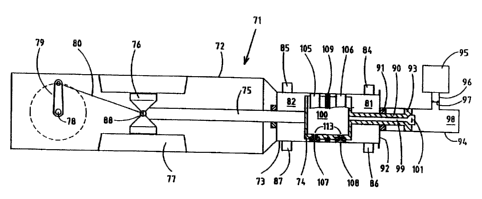
The horizontal piston compressor 71 shown in Fig. 1
comprises a frame 72, in which a cylinder 73 is accom-
modated. The cylinder 73 contains a piston 74, which
reciprocable in the cylinder 73. In Fig. 1 the bottom part
of the piston is shown in section, and the top part in
elevation.
A piston rod 75 is fixed to the piston 74 at its
right end in Fig. 1, and at its left end in Fig. 1 is
connected to crosshead 76. The crosshead 76 is guided
reciprocably in a horizontal straight line in the frame 72
of the compressor by means of guides 77.
The movement of the croashead 76 is produced by
means of a crank mechanism, such as is generally known in
the case of horizontal piston compresaors. The rotary
movement of drive shaft 78 is transmitted to the crosahead
76 by way of the crank 79 immovably connected thereto and
connecting rod 80, which is fitted between the crank 79 and
the croashead 76.
The compressor shown in Fig. 1 is of the double-
acting type. Compression chambers 81 and 82 are formed in
the cylinder 73 by the piston 74. Each of the compression
chambers 81,82 is provided with an inlet valve 84,85 and an
outlet valve 86,87, respectively. On movement of the piston
74 in the direction of the crank mechanism, to the left in
Fig. 1, gas at a suction pressure is sucked by way of the
inlet valve 84 into the compression chamber 81. At the same
time the gas present in the compression chamber 82 is
compressed and discharged at a discharge pressure by way of
CA 02204534 2005-06-29
- 6 -
the outlet valve 87.
As the name horizontal piston compressor already
indicates, the frame 72 of the compressor is placed on a
bedplate in such a way that the cylinder 73 is situated in
a horizontal position. According to the present invention,
measures are proposed for the bearing support of the
piston/piston rod unit, formed by the piston 74 and the
piston rod 75. At the left end in Fig. 1 said unit rests by
way of the crosshead 76 on the frame 72, lubricating oil
generally being introduced between the guides 77 and the
crosshead 76. However, this support at the crosshead 76 is
unable to prevent the piston 74 from dragging along the
bottom part of the wall of the cylinder 73, in particular
because there will be a certain play between crosshead 76
and guides 77, which permits tilting of the crosshead 76,
and because the slim piston rod 75 will bend. The other
bearing means which support the piston/piston rod unit are
described below.
In the case of the exemplary embodiment shown in
Fig. 1 the piston 74 is provided with a rod 90, which
extends in line with the piston rod 75 at the other side of
the piston 74. The rod 90 projects through stuffing box 91
in cylinder cover 92 of the cylinder 73. The free end of
the rod 90 bears a piston part 93, which is situated in a
second cylinder 94 fitted on the cylinder cover 92.
Reference number 95 indicates diagrammatically a source for
gas. Said source 95, which can be formed by, for example, a
chamber connected to the delivery valves 86 and 87 of the
compressor, is in communication with compression chamber 98
in the cylinder 94 by way of conduit 96, which has a
suction valve 97 accommodated therein. The rod 90 has a
bore 99, which extends from the end face of the piston part
93 to chamber 100, which is formed in the piston 74. The
communication between the bore 99 and the compression
chamber 98 is controlled by a delivery valve 101, which is
accommodated in the piston part 93 and opens if
sufficiently high pressure is reached in the compression
chamber 98. During the reciprocating movement of the
piston/piston rod unit this ensures that gas under pressure
CA 02204534 2005-06-29
7 -
is constantly present in the chamber 100.
Around the piston 74, near each end face thereof, a
rider ring, which will be explained in further detail with
reference to Figs. 2, 3 and 4, is fitted in a peripheral
groove in the body of the piston 74. These essentially
identical rider rings 105 and 106 project over a short
distance beyond the body of the piston 74. An assembly of
piston rings 109 also lies around the body of the piston
74, at a point between the rider rings 105 and 106, in
order to prevent gas from flowing from the high-pressure
side of the cylinder 73 to the low-pressure side.
As can be seen in Fig. 1, the chamber 100 of the
piston 74 is in communication with one or more outflow
openings 107, 108 formed in each rider ring. The source,
which is formed by the chamber 100 combined with the part
of the compressor which supplies gas under pressure to said
chamber 100, should be designed in such a way that during
the operation of the compressor gas under pressure
constantly flows out of the chamber 100 to the outflow
openings 107 and 108. This means that the pressure in the
chamber 100 in every case should be higher than the maximum
delivery pressure of the gas in the compression chambers 81
and 82.
The gas forms a gas film between the rider rings
105, 106 and the smooth wall of the cylinder 73. The
bearing capacity of such a gas film is determined by the
pressure of the gas in the film and the surface over which
said pressure acts upon the part of the piston/piston rod
unit to be supported. This surface will be a section of the
bottom half of the rider ring here in each case.
In a variant of the piston compressor according to
Figure 1 which is not shown valve means are provided in the
piston 74, which ensure that at a certain gas pressure in
the compression chamber 81, 82, in which gas sucked in is
compressed, the communication between the chamber 100 and
the outflow opening 107 or 108 belonging to said
compression chamber is shut off, and a gas film is only
formed between the piston 74 and the cylinder 73 at the
low-pressure side of the piaton rings 109. This means that
CA 02204534 2005-06-29
- 8 _
the gas pressure in the chamber 100 can be lower than in
the case of the piston compressor shown in Fig. 1, which is
simple to achieve. Through producing an overlap between the
formation of the gas film at one side of the piston rings
109 and the fall-off of the gas film at the other side
thereof, it is ensured that a gas film is constantly
present between the piston and the cylinder.
In another variant which is not shown the rider
rings are not accommodated in a groove in the body-of the
piston, but the body of the piston is constructed of
several separate segments, and a rider ring is clamped
between two segments.
An exemplary embodiment of the rider rings 105 and
106 will now be explained with reference to the rider ring
105 shown in Figs. 2, 3 and 4. The rider ring 105 is an
annular element with an accurate cylindrical inside
diameter, which is adapted to the peripheral groove to be
formed in the body of the piston, in which groove the ring
is placed. However, the outer periphery of the rider ring
105 is not exactly cylindrical. As can be seen in Fig. 2,
the bottom segment of the outer periphery when the rider
ring is fitted has a slightly larger radius than the top
segment connecting thereto. The bottom segment extends
through an angle on either side of the vertical 110, and
the radius virtually corresponds to the radius of the
cylinder along which the rider ring moves. The reasons for
this design of the outer periphery is that for forming the
gas film between the belt 105 and the cylinder 73 it must
be possible to move the piston 74 upwards a slight distance
and sufficient play should remain for mechanical and
thermal deformation.
It can be seen from the section of Fig. 4 that a
nipple 111 is screwed into the rider ring, with a bore
which opens out in a circular end face 112. The end face
112 lies recessed relative to the outer periphery of the
rider ring 105. For the setting of the gas film it is
important that the outflow opening 122 in the nipple 111 is
in the form of a restriction for the gas flow. The outflow
opening 122 is in communication with the chamber 100 by way
CA 02204534 2005-06-29
- 9 -
of a bore 113 in the wall of the piston 74 (see Fig. 1).
As already mentioned earlier, the supporting
capacity of this gas bearing system is determined, inter
alia, by the effective surface over which the gas film
supports the piston/piston rod unit. In order to obtain a
large surface with a stable gas film, a pattern of grooves
is provided in the bottom segment of the rider ring 105,
which can be seen in particular from Fig. 3. The pattern of
grooves comprises two parallel main grooves 120, 121, which
lie on either side of the nipple 111. It can be seen from
Fig. 2 that each of the main grooves 120, 121 extends
through an angle symmetrically towards either side, along
outflow opening 122 of the nipple 111 situated on the
vertical 110. A central transverse groove 123 connects the
two main grooves 120, 121 to the outflow opening 122. At
their ends the main grooves 120, 121 are connected by
transverse grooves 124. Transverse grooves 125 - 130, lying
symmetrically relative to the vertical 110, connect the two
main grooves 120, 121 and in this way form fields 131 -
138. The fields 131 - 138 lie flush with the remaining part
of the bottom segment of the rider ring 105.
The pattern of grooves described above shows only
one possible solution. In certain situations it will even
be possible to dispense entirely with the pattern of
grooves and provide just one or more outflow openings in
the form of a simple bore.
It is preferable to make the rider rings 105 and
106 from a material which has advantageous emergency
running properties, so that if the gas film accidentally
falls off no undesirable wear of the cylinder wall will
occur. For that reason, a material like PTFE or white metal
is preferred. Through this choice of the material of the
rider rings, allowance is made for the situation where the
gas film in the bearing means according to the invention
need not be complete and/or will not be complete in
practice, in other words, direct friction contact can still
occur between parts of the piston, in the case of Fig. 1
the rider rings 105, 106 and the cylinder.
In Figure 1 the source for the gas which is
CA 02204534 2005-06-29
- 10 -
supplied under pressure to the corresponding gas bearings
of the piston/piston rod unit which are externally
pressurised is indicated only diagrammatically, in order to
indicate that many solutions are suitable. In principle,
the main condition which such a source must meet is that
gas should flow constantly out of one or more of the
outflow openings, in order to maintain a gas film between
the cylinder and the piston. The outflow of the gas from an
outflow opening will in this case depend, inter alia, on
the pressure in the region to which the gas flows. That is
why it is particularly important in the case of the
exemplary embodiment described with reference to Fig. 1
that the source can supply gas at a pressure which is
higher than the maximum delivery pressure of the gas in a
compression chamber of the compressor. For example, it is
possible for the source to be formed by a higher pressure
stage of the same compressor or of another compressor.
Moreover, in particular in the situation where the gas of
the gas film enters into the cylinder, it is preferable for
the gas supplied to the gas bearings provided externally
with pressure to be the same as the gas to be compressed by
the compressor.
The horizontal piston compressor 141 shown in Fig.
5 comprises a frame 142, in which a cylinder 143 is
accommodated. The cylinder 143 contains a piston 144, which
is movable to and fro in the cylinder 143. In Fig. 5 the
bottom part of the piston 144 is shown in longitudinal
section, and the top part is shown in elevation. A piston
rod 145 is fixed at its right end in Fig. 5 to the piston
144, and at its left end in Fig. 5 is coupled to croashead
146. The crosshead 146 is guided by means of guides 147 in
such a way that it is movable reciprocably in a horizontal
straight line in the frame 142 of the compressor.
The movement of the crosshead 146 is produced by
means of a crank mechanism, such as is generally known in
the case of horizontal piston compressors. The rotary
movement of drive shaft 148 is transmitted to the croashead
146 by way of the crank 149 fixed thereto and connecting
rod 150, which is fitted between the crank 149 and the
CA 02204534 2005-06-29
- 11 -
crosshead 146.
The compressor shown in Fig. 5 is of the double-
acting type. Compression chambers 151 and 152 are formed in
the cylinder 143 by the piston 144. The compression chamber
151 is provided with an inlet valve 154 and an outlet valve
156, the compression chamber 152 is provided with inlet
valve 155 and outlet valve 157. On movement of the piston
144 in the direction of the crank mechanism, to the left in
Fig. 6, gas at a suction pressure is sucked by way of the
inlet valve 154 into the compression chamber 151. after
reversal of the direction of movement of the piston 144 the
gas in the compression chamber 151 is compressed and
discharged at a discharge pressure by way of the outlet
valve 156.
As the name horizontal piston compressor already
indicates, the frame 142 of the compressor is placed on a
bedplate in such a way that the cylinder 143 is situated in
a horizontal position. According to the present invention,
measures are proposed for the bearing support of the
piston/piston rod unit, formed by the piston 144 and the
piston rod 145. At the left end in Fig. 5 said unit rests
by way of the crosshead 146 on the frame 142, lubricating
oil generally being introduced between the guides 147 and
the crosshead 146. However, this support at the crosshead
146 is unable to prevent the piston 144 from dragging along
the bottom part of the wall of the cylinder 143, in
particular because there will be a certain play between
crosshead 146 and guides 147, which permits tilting of the
crosshead 146, and because the slim piston rod 145 will
bend. The other bearing means which support the
piston/piston rod unit are described below.
The piston 144 is provided with a cavity, and a
partition 160 divides said cavity into two chambers 161 and
162. The chamber 161 is in communication by way of delivery
valves 164 and 165 with the compression chambers 151 and
152. The valves 164 and 165 are designed in such a way that
they open when the pressure is sufficiently high in the
corresponding compression chamber. Around part of the
bottom half of the periphery of the piston 144 lie one or
CA 02204534 2005-06-29
- 12 -
more - in this case two - segment-shaped annular elements
168, 169 (indicated by dashed lines), which are each
provided with one or more outflow openings 170, 171. Said
outflow openings 170, 171 are in communication with the
chamber 161, for example in the manner described with
reference to Figs. 1 - 4.
The gas coming out of the chamber 161 at the
outflow openings 170, 171 forms a very thin gas film
between the corresponding annular element and the wall of
the cylinder. Through the presence of an assembly of piston
rings 173, 175 on either side of the two annular elements
168, 169, it is ensured that the pressure in the region of
the gas films between the annular elements 168, 169 and the
cylinder wall is always lower than the delivery pressure in
the compression chambers 151 and 152. Due to the fact that
the chamber 161 is in each case supplied with gas at a
pressure which lies close to the delivery pressure in the
compression chambers 151 and 152, a constant supply of gas
to the gas film is ensured.
The gas supplied into the space between the two
assemblies of piston rings 173, 175 must, of course, also
be discharged again. This is achieved through openings 177
in the wall of the piston 144, which connects the space
between the piston rings 173, 175 to the chamber 162. Said
chamber 162 is in turn in communication with the
compression chambers 151 and 152 by way of suction valves
178, 179. If the pressure in the compression chamber in
question is sufficiently low, the suction valve 178 or 179
in question will open, and gas will be discharged from the
chamber 162. If the volume of the chambers 161 and 162 is
made sufficiently great, the changes in the pressure in the
chambers 161, 162 are limited, and the gas flow which is
necessary for maintaining a stable gas film between the
annular elements 168, 169 and the cylinder wall 143 can be
obtained.
The piston 144, as described above and shown in
Figure 5, can be used very advantageously for the conver-
sion of existing piston compressors of the "oil-lubricated"
type to "oil-free" compressors. For the piston 144 has all
CA 02204534 2005-06-29
- 13 -
the elements which are necessary for forming a stable gas
bearing system, so that essentially only the piston of the
existing compressor need be replaced by the piston 144.
The horizontal piston compressor 191 shown in
Fig. 6 comprises a frame 192 which accommodates a cylinder
193. The cylinder 193 contains a piston 194, which is
reciprocable in the cylinder 193. In Fig. 6 the bottom part
of the piston 194 is shown in section and the upper part in
elevation. A piston rod 195 is fixed to the piston 194 at
its right end in Fig. 6, and at its left end in Fig. 6 is
connected to crosshead 196. The crosshead 196 is guided
reciprocably in a horizontal straight line in the frame 192
of the compressor by means of guides 197.
The movement of the crosshead 196 is produced by
means of a crank mechanism, such as is generally known in
the case of horizontal piston compressors. The rotary
movement of drive shaft 198 is transmitted to the crosshead
196 by way of the crank 199 fixed thereto and connecting
rod 200, which is fitted between the crank 199 and the
crosshead 196.
The compressor shown in Fig. 6 is of the double-
acting type. Compression chambers 201 and 202 are formed in
the cylinder 193 by the piston 194. The compression chamber
201 is provided with an inlet valve 204 and an outlet valve
206, while the compression chamber 202 is provided with
inlet valve 205 and outlet valve 207. On movement of the
piston 194 in the direction of the crank mechanism, to the
left in Fig. 6, gas at a suction pressure is sucked by way
of the inlet valve 204 into the compression chamber 201.
After the reversal of the direction of movement of the
piston 294, the gas in the compression chamber 201 is
compressed and discharged at a delivery pressure through
the outlet valve 206.
As the name horizontal piaton compressor already
indicates, the frame 192 of the compressor is placed on a
bedplate in such a way that the cylinder 193 is situated in
a horizontal position. According to the present invention,
measures are proposed for the bearing support of the
piston/piston rod unit, formed by the piston 194 and the
CA 02204534 2005-06-29
- 14 -
piston rod 195. At the left end in Fig. 6 said unit rests
by way of the crosshead 196 on the frame 192, lubricating
oil generally being introduced between the guides 197 and
the crosshead 196.
The piston 194 has a cavity, and a partition 210
divides the cavity into two chambers 211 and 212. Two
hollow rods 213 and 214 are fitted on the piston 194.
Cylinder cover 215 is designed in such a way that two
chambers 216 and 217 are formed, and the rods 213 and 214
project, sealed by a corresponding stuffing box, into the
chambers 216 and 217 respectively. The chamber 216 is con-
nected by way of a conduit 220 to a pressure chamber 221,
which in turn is connected to the two delivery valves 206,
207 of the cylinder 193. The chamber 217 is connected by
way of conduit 225 to a suction chamber 226, which in turn
is connected to the suction valves 204, 205 of the cylinder
193. This arrangement ensures that a gas under pressure is
supplied constantly into the chamber 211, while gas is
discharged from the chamber 212.
Around part of the bottom half of the periphery of
the piston 194 lie one or more - in this case two -
segment-shaped annular elements 238, 239 (indicated by
dashed lines), which are each provided with one or more
outflow openings 240, 241. Said outflow openings 240, 241
are in communication with the chamber 211, for example in
the manner described with reference to Figs. 2 - 4.
The gas coming out of the chamber 211 at the
outflow openings 240, 241 forms a film between the
corresponding annular element and the wall of the cylinder.
Through the presence of an assembly of piston rings 243,
245 on either side of the two annular elements 238, 239, it
is ensured that the pressure in the region of the gas film
between the annular elements 238, 239 and the cylinder wall
is always lower than the delivery pressure in the
compression chambers 201 and 202. Due to the fact that the
chamber 211 is in each case supplied with gas at a pressure
which lies close to the delivery pressure in the
compression chambers 201 and 202, a constant supply of gas
to the gas film is ensured.
CA 02204534 2005-06-29
- 15 -
The gas supplied into the space between the two
assemblies of piston rings 243, 245 is discharged through
openings 247 in the wall of the piston 194, which connect
the space between the piston rings 243, 245 to the chamber
212.
The horizontal piston compressor 841 shown in
Fig. 7 comprises a frame 842 which accommodates a cylinder
843. The cylinder 843 contains a piston 844, which is
reciprocable in the cylinder 843. In Fig. 7 the bottom part
of the piston 844 is shown in section and the upper part in
elevation. A piston rod 845 is fixed to the piston 844 at
its right end in Fig. 7, and at its left end in Fig. 8 is
connected to crosshead 846. The crosshead 846 is guided
reciprocably in a horizontal straight line in the frame 842
of the compressor by means of guides 847.
The movement of the crosshead 846 is produced by
means of a crank mechanism, such as is generally known in
the case of horizontal piston compressors. The rotary
movement of drive shaft 848 is transmitted to the crosshead
846 by way of the crank 849 fixed thereto and connecting
rod 850, which is fitted between the crank 849 and the
crosshead 846.
The compressor shown in Fig. 7 is of the double-
acting type. Compression chambers 851 and 852 are formed in
the cylinder 843 by the piston 844. The compression chamber
851 is provided with an inlet valve 854 and an outlet valve
856, while the compression chamber 852 is provided with
inlet valve 855 and outlet valve 857. On movement of the
piston 844 in the direction of the crank mechanism, to the
left in Fig. 7, gas at a suction pressure is sucked by way
of the inlet valve 854 into the compression chamber 851.
After the reversal of the direction of movement of the
piston 844, the gas in the compression chamber 851 is
compressed and discharged at a delivery pressure through
the outlet valve 856.
As the name horizontal piston compressor already
indicates, the frame 842 of the compressor is placed on a
bedplate in such a way that the cylinder 843 is situated in
a horizontal position.
CA 02204534 2005-06-29
- 16 -
According to the present invention, measures are
proposed for the bearing support of the piston/piston rod
unit, formed by the piston 844 and the piston rod 845. At
the left end in Fig. 7 said unit rests by way of the
crosshead 846 on the frame 842, lubricating oil generally
being introduced between the guides 847 and the crosshead
846. However, this support at the crosshead 846 is unable
to prevent the piston 844 from dragging along the bottom
part of the wall of the cylinder 843, in particular because
there will be a certain play between croashead 846 and
guides 847, which permits tilting of the crosshead 846, and
because the slim piston rod 845 will bend. The other
bearing means which support the piston/piston rod unit are
described below.
The piston 844 has a chamber 861. The chamber 861
is in communication by way of delivery valves 864 and 865
with the compression chambers 851 and 852 respectively. The
valves 864 and 865 are designed in such a way that they
open when the pressure is sufficiently high in the
corresponding compression chamber. Around part of the
bottom half of the periphery of the piston 844 lie one or
more -in this case two - annular elements 868, 869, which
are each provided with one or more outflow openings 870,
871. Said outflow openings 870, 871 are in communication
with the chamber 861, for example in the manner described
with reference to Figs. 2 - 4.
The gas coming out of the chamber 861 at the
outflow openings 870, 871 forms a very thin gas film
between the corresponding annular element and the wall of
the cylinder. Through the presence of an assembly of piston
rings 873, 875 on either side of the two annular elements
868, 869, it is ensured that the pressure in the region of
the gas films between the annular elements 868, 869 and the
cylinder wall is independent of the delivery pressure in
the compression chambers 851 and 852. Due to the fact that
the chamber 861 is in each case supplied with gas at a
suitable pressure, a continuous supply of gas to the gas
film can be ensured.
The gas supplied into the space between the two
CA 02204534 2005-06-29
- 17 -
assemblies of piston rings 873, 875 must also be discharged
again. This is achieved by gas discharge means, which in
this case are in the form of one or more outflow openings
890 in the wall of the cylinder 843. Said outflow opening
890 lies in such a position that it is in communication
with the space which is bounded by the piston 844, the
cylinder 843 and the piston rings 873, 875. Connected to
the outflow opening 890 is a control device 891, which is
designed to control the outflow of gas through the outflow
opening 890. With this device 891, which can be, for
example, a simple throttle valve, the gas pressure in this
space can be set and a very stable gas film can be
obtained.
With the measures according to the invention
described with reference to Figure 7 it is simple to
convert an existing piston compressor of the oil-lubricated
type to an "oil-free" compressor, or to provide an "oil-
free" compressor with a gas bearing system. For this,
essentially only the piston need be replaced by a piston of
the type in Figure 7, while for the provision of the
outflow opening for the gas forming a gas film use can be
made of the lubricating oil supply opening generally
already present in the cylinder.
It will be clear that the solutions described above
for the bearing support of the piston/piston rod unit
relative to the stationary part of the compressor can also
be used in the case of single-acting or tandem compressors.