Note: Descriptions are shown in the official language in which they were submitted.
CA 02204563 1997-OS-06
EYESAFE LASER TRANSMITTER WITH SINGLE RESONATOR CAVITY
FOR BOTB PDMP LASER AND OPTICAL PARAMETRIC OSCILLATOR
BACKGROUND OF THE INVENTION
1. FIELD OF THE INVENTION
This invention relates to laser systems which shift
the wavelength of light emitted by the laser and, more
particularly, to a laser system which utilizes the same
optical resonator cavity for both the pump laser and the
optical parametric oscillator.
2. DISCUSSION
Eyesafe laser transmitters of the type discussed
herein typically include two resonator cavities. A first
resonator cavity operates in conjunction with the pump,
and a second resonator cavity operates in conjunction with
the optical parametric oscillator (OPO). The two-
resonator configuration requires a total of three
resonator mirrors for operation of the laser. The use of
three resonator mirrors significantly complicates
alignment of the mirrors.
CA 02204563 2000-03-15
2
In addition to alignment considerations, typical eyesafe lasers
include a relatively short OPO cavity which results in high Fresnel members,
thereby reducing the overall quality of the laser beam. Further, the spatial
overlap
of these cavities is often significantly limited by the present arrangements.
Therefore, it is an object of the present invention to provide an
improved laser system.
It is a further object of an aspect of the present invention to provide
a laser system which uses the same optical cavity for the pump laser and the
optical
parametric oscillator.
It is still a further object of an aspect of the present invention to
provide a laser system which requires only two resonator mirrors to operate
the
eyesafe laser transmitter.
It is still a further object of an aspect of the present invention to
provide a laser system which simplifies optical alignment of the two mirrors
in the
eyesafe laser.
It is still a further object of an aspect of the present invention to
provide a laser system having a generally longer optical parametric oscillator
cavity, thereby providing improved output beam quality.
It is still a further object of an aspect of the present invention to
provide a laser system having improved spatial overlap of the pump and optical
parametric oscillator cavity modes.
SUMMARY OF THE INVENTION
According to one aspect of the present invention there is provided a
laser comprising a resonator cavity resonant at a pumping frequency and at an
output frequency. The resonator cavity has a mirror on at least one end for
partially reflecting light of the pumping frequency within the resonator
cavity and
for partially reflecting light of the output frequency within the resonator
cavity. A
pump laser is disposed within the resonator cavity for supplying light at the
pumping frequency to the laser cavity. An optical parametric oscillator
disposed
CA 02204563 2000-03-15
3
within the resonator cavity converts the light at the pumping frequency to
light at
the output frequency. Further, the resonator cavity, the pump laser, and the
optical
parametric oscillator are optically aligned. Still further, the optical
parametric
oscillator and the pump laser use the same resonator cavity such that the
resonator
cavity requires not more than two resonator mirrors.
According to another aspect of the present invention there is
provided a laser comprising:
a resonator cavity resonant at a pumping frequency and at an output
frequency, said resonator cavity defining a common optical path;
a first mirror disposed at one end of the resonator cavity along the
optical path and reflecting light at the pumping frequency and the output
frequency
towards the interior of the resonator cavity;
a second mirror disposed at an opposite end of the resonator cavity
from the first mirror along the optical path and reflecting light at the
pumping
frequency toward the interior of the resonator and partially reflecting light
at the
output frequency toward the interior of the resonator cavity;
a pump laser disposed within the resonator cavity along the optical
path for supplying light at the pumping frequency;
a Q-switch disposed along the optical path for increasing the
intensity of light at the pumping frequency;
a filter disposed along the optical path for polarizing light into a
planar alignment; and
an optical parametric oscillator disposed within the resonator cavity
along the optical path for converting the polarized light at the pumping
frequency
to light at the output frequency,
wherein the optical parametric oscillator and the pump laser both
are housed within and use the resonator cavity.
According to yet another aspect of the present invention there is
provided a laser comprising:
a resonator cavity resonant at a pumping frequency and at an output
frequency, said resonator cavity defining a common optical path;
CA 02204563 2000-03-15
3a
a first mirror disposed at one end of the resonator cavity along the
optical path and reflecting light at the pumping frequency toward the interior
of the
resonator cavity and partially reflecting light at the output frequency toward
the
interior of the resonator cavity;
a corner cube disposed at an opposite end of the resonator cavity
from the first mirror along the optical path for redirecting light in the
direction of
the first mirror;
a pump laser disposed within the resonator cavity along the optical
path for supplying light at the pumping frequency;
a Q-switch disposed along the optical path for increasing the
intensity of light at the pumping frequency;
a filter disposed along the optical path for polarizing light into a
planar alignment; and
an optical parametric oscillator disposed within the resonator cavity
along the optical path for converting light at the pumping frequency to light
at the
output frequency;
wherein the optical parametric oscillator and the pump laser both
are housed within and use the resonator cavity.
BRIEF DESCRIPTION OF THE DRAWINGS
FIG. 1 is a laser system arranged in accordance with the principles
of the present invention;
FIG. 2 is a plot of the absorption spectrum of the Q-switch shown in
FIG. 1;
CA 02204563 1997-OS-06
4
FIG. 3 is a plot of the absorption spectrum of the
Nd:YAG;
FIG. 4 is a second embodiment of the laser arranged
in accordance with the principles of the present
invention;
FIG. 5 is yet another embodiment of the laser
arranged in accordance with the principles of the present
invention;
FIG. 6 is yet a further embodiment of the laser
arranged in accordance with the principles of the present
invention; and
FIG. 7 is a block diagram for a range processing
system using the laser described in the present invention.
DETAILED DESCRIPTION OF A PREFERRED EMBODIMENT
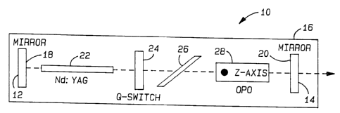
In FIG. 1, the laser system 10 includes a first
mirror 12 and a second mirror 14 defining the ends of an
optical cavity 16. Mirror 12 includes an interior surface
18 which is high-reflectivity coated (approximately 100%)
to reflect light having a wavelength of 1.06 microns and
approximately 88o reflectivity coated to reflect light
having a wavelength of 1.57 microns. Mirror 14 includes
an interior surface 20 which is high-reflectivity coated
(approximately 100%) to reflect light having a wavelength
of 1.06 microns and partially reflectivity coated at 70%
to reflect light having a wavelength of 1.57 microns. The
CA 02204563 1997-OS-06
reflectivity coating of interior surfaces 18 and 20 of
mirrors 12 and 14, respectively, coincides with the
wavelengths of light emitted by the pump (1.06 microns)
and the optical parametric oscillator 28 (1.57 microns).
5 Mirrors 14 and 12 are preferably separated by
approximately 14 centimeters. While shown as being 88%
reflective of 1.57 microns, mirror 12 preferably is 100%
reflective of 1.57 micron light. Further, all other
components of the resonator cavity 16 are typically anti-
l0 reflective coated to absorb light at both 1.06 microns and
1.57 microns.
Within the interior of the resonator cavity 16 a
neodymium-doped yttrium aluminum garnet (Nd:YAG) rod 22 of
dimensions 2.5 millimeters x 50 millimeters is flashlamp-
pumped. Preferably both the rod 22 and the lamp are
enclosed within a reflective ceramic pump cavity. The rod
22 provides gain for light at a wavelength of 1.06
microns. The Q-switch 24 initially absorbs light at 1.06
microns until a predetermined amount of energy has been
absorbed. Q-switch 24 then becomes relatively
transparent, thereby resulting in the onset of laser
action and subsequently causing the release of stored
energy as 1.06 micron light. The Brewster plate 26 causes
the 1.06 micron light to be linearly polarized. The
polarized 1.06 micron light, after reaching sufficient
intensity, is converted to 1.57 micron light by the
CA 02204563 1997-OS-06
6
optical parametric oscillator (OPO) 28. The OPO 28
includes as the active element a potassium titanyl
phosphate (KTP) crystal having its Z-axis shown as
projecting outward from the plane of FIG. 1. This KTP
crystal orientation, as well as the orientation of the
Brewster plate, were predetermined to meet type II phase
matching conditions for KTP, i.e., the 1.06 micron and
1.57 micron light are linearly polarized perpendicular to
the Z-axis of the KTP. Thus, it can be seen from FIG. 1
that the optical parametric oscillator 28 and Nd:YAG~ rod
22 share a common resonator cavity 16. It will be noted
by one skilled in the art that the reflective coatings
applied to interior surface 20 of mirror 14 may be applied
to the output side of OPO 28, thereby eliminating mirror
14 .
In operation, the Nd:YAG rod 22 is flashlamp-pumped
or diode-pumped. The 1.06 micron light is Q-switched
using a 0.5 optical density (low intensity transmittance)
tetravalent-doped chromium yttrium aluminum garnet
(Cr'':YAG) crystal. The threshold for the laser in FIG. 1,
using this Q-switch, is about 3.6 joules of electrical
energy input to the flashlamp. In the embodiment
described in FIG. 1, approximately i.2 millijoules of
output energy emitted from mirror 14, while approximately
0.4 millijoules of output energy in the form of 1.57
micron light is emitted from mirror 12. Further, the
CA 02204563 1997-OS-06
7
surface coatings of Nd:YAG and Cr:YAG were anti-reflective
coated at 1.064 microns but not at 1.57 microns.
The low intrinsic losses of both the Cr4':YAG and
Nd':YAG at the optical parametric oscillator signal
wavelength can be seen in the absorption spectra of FIGS.
2 and 3, respectively. Of particular importance with
respect to FIGS. 2 and 3 is the relatively low loss at the
1.57 micron wavelength in both the Cr4':YAG and Nd':YAG
crystals.
FIGS. 4-6 depict alternative embodiments of the
eyesafe laser which utilizes the single optical cavity
concept. Referring to FIG. 4, the resonator cavity 40
includes a single mirror 42 having deposited on an
interior surface 44 a high reflectivity mirror coating to
totally reflect light at a wavelength of 1.06 microns and
to partially reflect light at a wavelength of 1.57
microns. The resonator cavity 40 also includes a corner
cube or folding prism 46, which enables a single mirror
design. The Q-switch 48 comprising a Crq':YAG crystal
extending across both legs of the folded resonator cavity
40. The Nd:YAG rod 58 is flashlamp-pumped. The rod 22
provides gain for light at a wavelength of 1.06 microns.
Q-switch 48 operates as described with respect to FIG. 1
to absorb light at 1.06 microns, then release the stored
~5 energy subsequent to the onset of laser action. The
Brewster plate 50 causes the 1.06 micron light to be
CA 02204563 1997-OS-06
8
linearly polarized. OPO 52 includes a KTP crystal and
converts the 1.06 micron light, after it reaches a
sufficient intensity, to 1.57 micron light. The 1.57
micron light is then partially transmitted through the
mirror 42 to provide an output laser beam. A particular
advantage realized by the folded resonator 40 of FIG. 4 is
that the resonator may be optically aligned prior to
insertion of the Q-switch 48. That is, inserting the Q-
switch does not disturb the alignment of the folded
resonator configuration 40.
FIG. 5 is arranged similarly to that of FIG. 4 and
like elements will be referred to using like reference
numerals. FIG. 5 includes the same elements as described
with respect to FIG. 4 except note that in FIG. 5, the Q-
switch 48 extends only across one leg of the folded
resonator cavity 40. FIG. 6 depicts a folding resonator
cavity 40 arranged similarly to that described in FIGS. 4
and 5. FIG. 6 further includes a combined Q-switch and
Brewster plate 56 which performs the dual function of
increasing the intensity of and polarizing light at 1.06
microns:
With reference to FIG. 7, a targeting system 60 is
shown which includes one of the laser as described in
FIGS. 1 and 4-6. The targeting system 60 includes a range
processor 62. Range processor 62 provides control signals
to a laser 64, which may be any of the lasers as described
CA 02204563 1997-OS-06
9
with respect to FIGS. 1 and 4-6. The laser 64 outputs a
single (or repeated) pulse directed to an object 66 which
has been selected for targeting. The laser pulse reflects
off of object 66 back in the direction of the laser 64.
A sensor 68 detects the reflected pulse. The sensor 68
provides an input signal to range processor 62. Range
processor 62 then determines the distance between the
laser 64/sensor 68 and the object 66.
Range processor 62 determines the distance in
accordance with the time differential between the sending
of the pulse by laser 64 and the receiving of the pulse by
sensor 68. Range processor 62 then computes the distance
and outputs the distance to targeting controlling 70.
Targeting controller 70 then determines a targeting
solution in accordance with the distance provided by range
processor 62 and other inputs (not shown). Targeting
controller then outputs the targeting solution to a
tracking device 72 whose orientation may be controlled by
targeting controller 70 in accordance with the range
information provided by range processor 62.
Several important aspects of the invention will now
be discussed.
1. It will be noted by one skilled in the art, that
with respect to FIG. 1, mirrors l2.and 14, resonator
cavity 16, and Nd:YAG rod 22 define a laser pump. The
Nd:YAG rod provides the gain medium for the pump laser.
CA 02204563 1997-OS-06
Q-switch 24 may optionally also be included as part of the
pump laser. Similarly, it will be understood by one
skilled in the art that when a mirror coating is applied
to the output side of the OPO, that mirror coating also
5 comprises part of the pump laser.
2. It will further be understood by those skilled
in the art that materials other than Nd:YAG may be
substituted therefor. For example, either of the
materials yttrium ortho-vanadate (Nd3:YV04) or YLF
10 (Nd''~LiYS4) may be readily substituted for the Nd:YAG rod.
These materials provide properties differing from the
Nd:YAG which may be attractive in particular applications
of the invention. In general, the rod may include one of
the following materials Nd, Nd'', and Yb3'.
3. Similarly, with respect to the OPO, other
nonlinear crystals may be substituted for the KTP crystal.
Examples of acceptable substitutes may include potassium
titanyl arsenate (KTA), rubidium titanyl arsenate (RTA),
potassium rubidium titanyl arsenate (KRTA), and the like.
These various crystals generally share the common property
that they can shift an incoming wavelength to an eyesafe,
typically 1 to 1-if microns, in a non-critically matched
phase condition but having a selection of crystals
available provides greater flexibility in the design of
~5 lasers for particular applications.
_..._.-... _ CA 02204563 1997-OS-06
11
4. Further, as stated above with respect to FIG. 1,
diode-pumping of the pump laser may be used as an
alternative to the flash lamp-pumping, as described.
From the foregoing, it can be seen that the
configuration of the present invention which uses the same
optical resonator cavity for both the pump laser and the
optical parametric oscillator, provides a much simpler
configuration. The simpler configuration eliminates a
resonator mirror, which in turn significantly simplifies
optical alignment of the device. The simplified optical
alignment also provides for a much longer optical
parametric oscillator cavity, which ultimately results is
better spacial overlap of the pump and OPO cavity modes,
thereby providing an improved laser output.
Although the invention has been described with
particular reference to certain preferred embodiments
thereof, variations and modifications can be effected
within the spirit and scope of the following claims.