Language selection

Search

Patent 2204826 Summary

Third-party information liability

Some of the information on this Web page has been provided by external sources. The Government of Canada is not responsible for the accuracy, reliability or currency of the information supplied by external sources. Users wishing to rely upon this information should consult directly with the source of the information. Content provided by external sources is not subject to official languages, privacy and accessibility requirements.

Claims and Abstract availability

Any discrepancies in the text and image of the Claims and Abstract are due to differing posting times. Text of the Claims and Abstract are posted:

  • At the time the application is open to public inspection;
  • At the time of issue of the patent (grant).
(12) Patent: (11) CA 2204826
(54) English Title: QUICK MULTIPLE CONNECT ELECTRICAL CONNECTOR
(54) French Title: CONNECTEUR INSTANTANE A COUPLAGE MULTIPLE
Status: Deemed expired
Bibliographic Data
(51) International Patent Classification (IPC):
  • H01R 4/38 (2006.01)
  • H01H 85/20 (2006.01)
  • H01R 4/50 (2006.01)
  • H01R 9/03 (2006.01)
  • H01R 11/26 (2006.01)
  • H01R 13/68 (2011.01)
  • H01R 13/68 (2006.01)
(72) Inventors :
  • SWENSON, ROGER M., SR. (United States of America)
(73) Owners :
  • SWENCO PRODUCTS, INC. (United States of America)
(71) Applicants :
  • SWENSON, ROGER M., SR. (United States of America)
(74) Agent:
(74) Associate agent:
(45) Issued: 2000-11-07
(22) Filed Date: 1997-05-08
(41) Open to Public Inspection: 1998-04-03
Examination requested: 1998-01-29
Availability of licence: N/A
(25) Language of filing: English

Patent Cooperation Treaty (PCT): No

(30) Application Priority Data:
Application No. Country/Territory Date
08/720,912 United States of America 1996-10-03

Abstracts

English Abstract


A quick connect electrical connector for
connecting the bare ends of a pair of electrical wires. It
comprises a non-conductive first coupling member, having a
plurality of connection chambers, each connection chamber
having a threaded wall and a central axis. A common
conductive connector member is fixedly mounted in the
coupling member and having a plurality of bullet-shaped
ends, one in each connection chamber with the end surfaces
of the coupling member tapering inwardly to a tip. A
corresponding plurality of non-conductive second coupling
members having an externally threaded wall and internal
throughbore having first and second ends and a first
conically shaped annular wall surface. The first conically
shaped surface and the bullet-shaped connector portions are
spaced a variable distance apart when the threaded surfaces
are engaged.


French Abstract

Connecteur électrique instantané permettant de raccorder les extrémités nues de deux fils. Le connecteur comprend un premier dispositif de couplage non conducteur constitué d'un certain nombre de chambres de connexion ayant des parois filetées et un axe central. Un conducteur commun, fixé dans le dispositif de couplage, possède un certain nombre d'extrémités cylindriques placées dans chaque chambre de connexion, de sorte que le diamètre des extrémités du dispositif de couplage décroît vers l'intérieur jusqu'à la pointe. Un certain nombre de deuxièmes dispositifs de couplage non conducteurs correspondants ayant une paroi externe filetée et un trou interne comprennent deux orifices et une paroi annulaire conique. Lorsque les surfaces filetées entrent en contact, l'espace entre la paroi annulaire conique du trou et les sections cylindriques du conducteur est variable.

Claims

Note: Claims are shown in the official language in which they were submitted.


WHAT IS CLAIMED IS:
1. A quick connect electrical connector for
connecting the bare ends of a pair of insulated flexible
electrical wires comprising:
a non-conductive first coupling member, said
non-conducting first coupling member having a plurality of
connection chambers, each connection chamber having an
annular internally threaded wall and a central axis,
a common conductive connector member, said common
conductive connector member being fixedly mounted in said
non-conductive first coupling member, said common
conductive connecting member having a plurality of
bullet-shaped end surfaces with each of said end surfaces tapering
inwardly to a tip and being positioned in one of said
connection chambers, respectively,
a corresponding plurality of non-conductive second
coupling members, each non-conductive second coupling
member having an externally threaded annular wall and an
internal throughbore, said throughbore having first and
second ends, the first end of each said throughbores having
a first conically shaped annular wall surface, said first
conically shaped surface and said bullet-shaped connector
end surfaces being spaced a variable distance apart when
said threaded surfaces are engaged, each said second end of
said throughbore having a second conical surface having an
apex end for guiding loose wire strands to said apex end,


whereby when the bare end of one of said electrical
wires is inserted into one of said second end throughbore
in said second coupling members, respectively, each said
wire end is guided to said apex end and splayed off the
central axis by said bullet-shaped end surface to a
position between said spaced conically-shaped surfaces and
rotation of said first, second non-conductive coupling
members relative to said first non-conductive coupling
member causes said internal and external threads to reduce
said distance and clamp said bare ends of said electrical
wires between said first and second conically-shaped
surfaces in each said connection chamber, respectively.


2. A connector for splicing the free ends of two or
more flexible electrical wires comprising:
a non-conductive body member having at least a pair of
connection chambers, each connection chamber having a
threaded bore, respectively,
a common integral conductive member, said common
integral conductive member having (1) at least a pair of
rounded tip protrusions, one rounded tip protrusion
extending into one connection chamber, respectively, and
(2) a central portion fixedly secured in said
non-conductive body member,
at least a pair of hollow non-conductive male members,
each hollow non-conductive male member having an inner
surface shaped complementary to the shape of said rounded


tip protrusions, and a threaded external surface portion
for threaded engagement with said threaded bore,
respectively,
whereby the respective free ends of said two or more
flexible wires can be received in said connection chambers,
respectively, and each of said at least a pair of hollow
non-conductive male members threadedly engaged with said
threaded bores clampingly engage said ends of said two or
more flexible electrical wires between said complementary
shaped surfaces and said rounded tips, respectively, which
said hollow non-conductive male members are axially moved
relative to said body member.


3. The connector defined in Claim 2 wherein said
connection chambers are coaxial.


4. The connector defined in Claim 2 wherein said
connection chambers are not coaxial.


5. The connector defined in Claim 4 wherein there
are at least three connection chambers.


6. A plurality of connectors as defined in Claim 2
and tear tab means between each non-conductive body member.


Description

Note: Descriptions are shown in the official language in which they were submitted.


CA 02204826 1997-0~-08

QUIC~ MnLTIPLE CO~N~1 ELECTRICAL r~N~


RA~GROUND AND BRIEF DESCRIPTION OF THE lNV~ lON
The present invention is an improvement on the quick
connect electrical connector disclosed in my Patent No.
5,228,875 issued July 20, 1993. In my Patent No.
5,228,875, I disclose a quick blind connect electrical
connector for the bare end of electrical wires in which
there is one connection chamber for making blind electrical
connections.
An object of the present invention is to provide a
device of the character disclosed in my Patent No.
5,228,875 in which dual or multiple blind connection
chambers are provided. In a preferred embodiment of the
present invention, a bullet-shape ended conductive member
is fixedly secured in the central portion of a non-
conductive female coupling dividing the non-conductive
female coupling member into two or more connection
chambers, one connection chamber for each wire end. The
internal walls of the connection chambers are threaded so
that each connection chamber threadably receives a non-
conductive male coupling member. Each male coupling member
has a bore therethrough which is shaped and configured
similar to the bore and shaping of the non-conductive male
coupling members disclosed in my above-mentioned patent for
guiding the wire ends and clamping the wire ends to a

CA 02204826 1997-0~-08


common electrical conductor. The non-conductive male
coupling member has a first end having a conically-shaped
annular wall which is complementary to the conically-shaped
or bullet end surface of a conductive metal connector
member. The conically-shaped surfaces on the male coupling
member and the metal connector member are spaced a distance
apart to receive the wire end so that when the bare end
wire is inserted into the bore, it is first guided to the
center of the throughbore and then off axis by the
conically-shaped end surface of the metal connector and
positioned between the spaced conical surfaces and rotation
of one of the members relative to the other engages threads
to reduce the distance and clamp the bare end of the wire
between the conical surfaces.
Thus, the object of the invention is to provide an
improved blind electrical connector for multiple wires
which is low in cost, easy to manufacture and use and
requires no tools.

DESCRIPTION OF THE DRAWINGS
The above and other objects, advantages and features
of the invention will become more apparent when considered
with the following specification and accompanying drawings,
wherein:
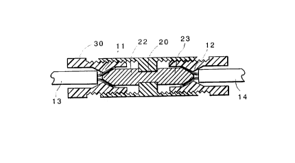
Figure l is an external view of the invention showing
the wires about to be inserted so that an electrical

CA 02204826 1997-0~-08


connection can be made therebetween and resulting in an
insulated coupling of two wires,
Figure 2 is a sectional view of the female non-
conductive member forming the housing for the two
S connection chambers of the present invention,
Figure 3 is a sectional view of first and second male
coupling members having interior configurations similar to
those disclosed in my aforementioned Patent No. 5,228,875,
Figure 4 is a sectional view of the interior metal
connector component incorporated in the invention,
Figure 5 shows the components of Figures 3 and 4
combined,
Figure 6 is a sectional view showing the two wires as
they are clamped in position in accordance with the
invention,
Figure 7A is a sectional view showing a three-wire
connector incorporating the invention, and Figure 7B is a
sectional view of a three-wire connector with the wires
connected,
Figure 8A is a sectional view showing a four-wire
connector incorporating the invention, and Figure 8B is a
sectional view of the four-wire connector with several
wires connected, and
Figure 9 is a top view of a further embodiment of the
invention.

CA 02204826 1997-05-08


DE~AT~.~n DESCRIPTION OF THE INV~ 10N
Referring to Figure 1, an electrical connector 10 for
connecting the bare ends 11, 12 of a pair of wires 13 and
14, respectively. It includes an non-conductive first
coupling member 15 which may be circular, square,
triangular or any other configuration. Non-conductive
first coupling member 15 forms a housing for connection
chambers 16 and 17 (see ~igure 2 ? . Each of the connecting
chambers have internally threaded walls 18 and lg,
respectively, and a partition member 20 which mounts or
secures a common metal connector member 21. The metal
connector member 21 is fixedly mounted in partition 20 by
being molded in, or glued in, or otherwise fixed in place.
Common metal connector member 21 has a pair of bullet-
shaped or conically-shaped projections 22 and 23,
respectively, which project into connection chambers 16 and
17.
A pair of non-conductive second coupling members 30
and 31 having externally threaded walls 32, 33 and
knurlated thumb and forefinger grasp members 34, 35,
respectively. The externally threaded walls 32 and 33 are
threadably engaged with internally threaded bores 18 and
19, respectively. Each of the non-conductive second
coupling members 30 and 31 has a throughbore 36, 37,
2S respectively, with an inwardly projecting member 38, 39.
A first conical surface 40, 41 has an apex end 42, 43
constituting the narrowest portion of the throughbore. The

CA 02204826 1997-0~-08


conical surfaces 40, 41 serve the function of guiding the
loose wire strands to the apex end and thence upon the
bullet ends 22, 23 of metal connector member 21. The
opposite side of the apex end 43 includes a second conical
surface 44, 45, respectively, which coact with the bullet-
or conically-shaped ends 22, 23 to form a space into which
the bare wire ends 11 and 12 are splayed and guided by the
bullet-shaped ends 22 and 23 of connection member 21. The
apex 42 prevents the insulation wires from being jammed
into the space between the first and second conically-
shaped surfaces. Thus., when the bare ends of the
electrical wires are inserted into the second end of the
throughbore in the second coupling members, the bare wire
end is guided off the central axis by the bullet-shaped end
surfaces to be positioned between and the spaced conically-
shaped surfaces. When the user grasps the knurled ends 34,
35, and rotates them in a direction as to cause the
coupling members 30 and 31 to move inwardly, the wire ends
11 and 12 are tightly gripped or clamped between the
conically-shaped surfaces 44, 45 and the bullet-shaped
ends, respectively. The wires 11 and 12 can be clamped
simultaneously or separately.
Knurlations may also be formed on the housing member
15.
Figure 6 shows the bare wire ends clamped in position
in accordance with the invention.

CA 02204826 1997-0~-08


Figure 7A is a sectional view showing a three-wire
connector incorporating the invention. In this embodiment,
the housing member is comprised of a Y-shaped member 50
having three connection chambers Sl, 52 and 53 with
correspondingly shaped conical surfaces and apex ends.
Figure 7B shows the unit with the three different wires
secured in place. It will be appreciated that it is not
necessary to use all three connections, and two may be used
if that is all that is required.
Similarly, Figure 8A is a sectional view showing a
four-wire connector incorporating-the invention, and Figure
8B is a sectional view of the four-wire connector with
several wires connected. It will be appreciated that more
or less connections may be made and that the unit may be
made for five, six or seven units or more. In fact, it
will be further appreciated that several units such as
shown in Figures 1, 7 and 8 may be molded together and with
assorted colors for different colored wires and associated
wire sizes and/or with break-away tubs or connectors as
shown in Figure 9. In connection with wire size, it will
be appreciated that the different units may be made for
different size wire ranges with differing forms of
insulation thereon. Moreover, the non-conductive coupling
members may be color coded, if desired.
In Figure 9, a plurality of connectors 10-1, 10-2, 10-
3...10-N are interconnected by breakable tear tabs 60-1,
60-2...60-N for manufacturing, packaging and distribution

CA 02204826 1997-05-08


purposes. The connectors shown in Figures 7 and 8 can also
be connected with break-away tabs.
While a preferred embodiment of the in~ention has been
illustrated and described along with several modifications
S and adaptations of the invention, it will be appreciated
that other modifications, adaptations and changes will be
apparent to those skilled in the art.

Representative Drawing
A single figure which represents the drawing illustrating the invention.
Administrative Status

For a clearer understanding of the status of the application/patent presented on this page, the site Disclaimer , as well as the definitions for Patent , Administrative Status , Maintenance Fee  and Payment History  should be consulted.

Administrative Status

Title Date
Forecasted Issue Date 2000-11-07
(22) Filed 1997-05-08
Examination Requested 1998-01-29
(41) Open to Public Inspection 1998-04-03
(45) Issued 2000-11-07
Deemed Expired 2009-05-08

Abandonment History

There is no abandonment history.

Payment History

Fee Type Anniversary Year Due Date Amount Paid Paid Date
Application Fee $150.00 1997-05-08
Request for Examination $200.00 1998-01-29
Maintenance Fee - Application - New Act 2 1999-05-10 $50.00 1999-05-05
Maintenance Fee - Application - New Act 3 2000-05-08 $50.00 2000-03-27
Final Fee $150.00 2000-08-09
Registration of a document - section 124 $100.00 2000-10-04
Maintenance Fee - Patent - New Act 4 2001-05-08 $50.00 2001-04-11
Maintenance Fee - Patent - New Act 5 2002-05-08 $75.00 2002-04-26
Maintenance Fee - Patent - New Act 6 2003-05-08 $75.00 2003-04-29
Maintenance Fee - Patent - New Act 7 2004-05-10 $100.00 2004-05-05
Maintenance Fee - Patent - New Act 8 2005-05-09 $100.00 2005-04-19
Maintenance Fee - Patent - New Act 9 2006-05-08 $100.00 2006-04-12
Maintenance Fee - Patent - New Act 10 2007-05-08 $125.00 2007-04-26
Owners on Record

Note: Records showing the ownership history in alphabetical order.

Current Owners on Record
SWENCO PRODUCTS, INC.
Past Owners on Record
SWENSON, ROGER M., SR.
Past Owners that do not appear in the "Owners on Record" listing will appear in other documentation within the application.
Documents

To view selected files, please enter reCAPTCHA code :


To view images, click a link in the Document Description column. To download the documents, select one or more checkboxes in the first column and then click the "Download Selected in PDF format (Zip Archive)" or the "Download Selected as Single PDF" button.

List of published and non-published patent-specific documents on the CPD .

If you have any difficulty accessing content, you can call the Client Service Centre at 1-866-997-1936 or send them an e-mail at CIPO Client Service Centre.


Document
Description 
Date
(yyyy-mm-dd) 
Number of pages   Size of Image (KB) 
Claims 1997-05-08 3 98
Drawings 1997-05-08 5 108
Abstract 1997-05-08 1 23
Description 1997-05-08 7 215
Cover Page 2000-10-18 1 52
Cover Page 1998-04-17 1 53
Representative Drawing 1998-04-17 1 8
Representative Drawing 2000-10-18 1 7
Cover Page 2000-12-08 2 84
Cover Page 2000-12-07 1 53
Fees 2003-04-29 1 32
Correspondence 2000-11-22 2 54
Fees 2002-04-26 1 36
Fees 2005-04-19 1 29
Assignment 1997-05-08 3 96
Prosecution-Amendment 1998-01-29 1 40
Prosecution-Amendment 1998-06-04 2 39
Correspondence 2000-08-09 2 55
Assignment 2000-10-04 8 387
Fees 2000-03-27 1 34
Prosecution-Amendment 2000-12-08 2 40
Fees 2001-04-11 1 34
Fees 1999-05-05 1 36
Assignment 2000-10-04 6 171
Fees 2004-05-05 1 34
Fees 2006-04-12 1 29
Fees 2007-04-26 3 100
Correspondence 2008-04-16 2 37
Correspondence 2008-09-16 1 14
Correspondence 2008-09-16 1 36