Note: Descriptions are shown in the official language in which they were submitted.
CA 02204899 1997-0~-08
W096/16897 PCT~S9S/15101
--1--
CATALYTIC PROCESS AND APPARATUS FOR
CHLORINE DIOXIDE GENERATION
.. ~
The present invention is directed to a specific
process and a specific apparatus for generating
chlorine dioxide directly from aqueous solutions of
chloric acid or chloric acid/sodium chlorate mix-
tures employing an oxygen-evolving catalyst. In
particular, the present invention relates to a
specific process that employs the chemical reduction
of chloric acid with water in the presence of an
oxygen-evolving catalyst without the use of or
addition of either another acid or an added reducing
agent.
Furthermore, the present invention relates to
an apparatus for generating chlorine dioxide using a
reaction zone containing an oxygen-evolving catalyst
that is physically separate, but hydraulically
connected to an aqueous chloric acid/chlorine
dioxide gas disengagement zone.
Chlorine dioxide has found wide use as a
disinfectant in water treatment/purification, as a
bleaching agent in pulp and paper production, and in
a number of other uses because of its high oxidizing
power. There are a number of chlorine dioxide
generator systems available in the marketplace.
Most of the very large scale generators utilize an
alkali metAl chlorate salt, a reducing agent, and a
strong acid. If sodium chloride is employed as a
reducing agent or if hydrogen chloride is employed
CA 02204899 1997-0~-08
W O96/16897 PCTrUS95/lS101
as the acid, then a mixture of chlorine and chlorine
dioxide is produced.
Generally, the additional presence of chlorine
in a chlorine dioxide product is not desired and,
for that reason, many processes have been developed
to produce chlorine dioxide having little or no
chlorine concentration therein. These processes use
nonchlorine-containing acids such as sulfuric acid
and reducing agents such as hydrogen peroxide,
methanol or other organic compounds, sulfur dioxide
or other sulfur-oxygen species having a sulfur
valence of less than +6, nitrogen oxide, nitrogen
dioxide, or carbon monoxide and the like.
However, if organic compounds a~e used as
reducing agents in these processes, unreacted
volatile organics including formic acid may be
present in the chlorine dioxide product. Their
presence may be generally undesirable for many
applications. If sulfur-containing acids or
reducing agents are used, sulfate salts or sulfuric
acid may accumulate in the reaction system as
undesirable byproducts. If gaseous reducing agents
_
such as sulfur dioxide or carbon monoxide are
employed, complex reactor designs and process
control systems must be employed to prevent such
unreacted gaseous reducing agents from leaving the
reaction zone with the chlorine dioxide product.
Furthermore, prior art processes for the
production of chlorine dioxide that use alkali me~al
chlorates and excess acid precursors accumulate as
alkali metal salts in the reaction system. This
salt accumulation must be periodically removed from
CA 02204899 1997-0~-08
WO96/16897 PCT~S95/lS101
--3--
~ the system as an unwanted byproduct, either as a
solid or liquid solution. This periodical removal
may cause a temporary shutdown of the reaction
system as well as the end process that the chlorine
dioxide is being used to treat.
Numerous U.S. patents describe processes for
generating chlorine dioxide by reacting an alkali
metal chlorate, a mineral acid, and a reducing
agent. Examples of such U.S. patents included
4,938,943 (Norell); 4,978,517 (Norell et al.);
4,986,973 (Svedin et al.); 5,002,746 (Norell);
5,091,166 (Engstrom et al.); 5,091,167 (Engstrom et
al.); and 5,093,097 (Engstrom et al.)
Separately, it is known to generate chlorine
dioxide by reacting an aqueous solution of an alkali
metal chlorate and a mineral acid such as sulfuric
acid or phosphoric acid in the presence of selected
catalysts.
For example, U.S. Patent No. 4,362,707, which
issued to Hardee et al. on December 7, 1982, teaches
a process for generating chlorine dioxide reacting
an alkali metal chlorate and an acid in the presence
of catalyst comprising the mixture of valve metal
oxide and at least one of ruthenium oxide, iridium
oxide, palladium oxide, rhodium oxide, and platinum
oxide. Sulfuric acid, hydrochloric acid, and
phosphoric acids are the only explicitly named acids
for this process. (See col. 4, lines 47-50; col. 6,
lines 33-37; and claim 2 of the '707 patent.)
U.S. Patent Nos. 4,381,290 and 4,501,824, both
of which issued to Hardee et al. on April 26, 1983
and February 26, 1985, respectively, teach a process
for reacting an alkali metal chlorate with an acid
-0~-08
WO96/16897 PCT~S95/15101
feedstock in the presence of a heterogeneous
catalyst that is substantially insoluble in the
reactant solutions and is selected from at least one
ruthenium oxide, iridium oxide, palladium oxide,
rhodium oxide, and platinum oxide. Sulfuric acid,
hydrochloric acid, and phosphoric acid are the only
explicitly named acids for this process. See col.
4, lines 65-68; col. 6, lines 51-55; and claim 2 of
the '290 patent.
Also, it is known to generate chlorine dioxide
electrochemically from an aqueous feedstock solution
of an alkali metal chlorate and a mineral acid.
U.S. Patent No. 4,426,263, which issued to
Hardee et al. on January 17, 1984, teaches an
15 electro-chemical process for generating chlorine
dioxide involving electrolyzing the combination of a
chlorate-containing feedstock with an aqueous strong
acid in an electrolytic cell having an electro-
catalytic cathode, including certain platinum group
20 metal oxide mixtures. Sulfuric acid, hydrochloric
acid, and phosphoric acid are the only explicitly
named acids for this process. (See col. 4, lines
66-68; col. 6, lines ~6-50; and claims 1, 2, 3, and
7 of this '263 patent.) The electrochemical cell
25 for this process has an electrocatalytic cathode
mode from a platinum group metal oxide mixture
selected from a group consisting of ruthenium-
rhodium, ruthenium-palladium, rhodium-palladium,
iridium-rhodium, iridium-platinum, and ruthenium-
30 rhodium-palladium. 7
U.S. Patent No. 4,767,510, which issued to
Lipsztajn on August 30, 1988, teaches a process for
generating chlorine dioxide by an electrochemical
CA 02204899 1997-0~-08
WO96/16897 PCT~S95/lS101
--5--
process where an aqueous acidic solution of chlorate
ions having a total acid greater than 7 normal
sulfuric acid is subjected to a cathodic electrical
current. The cathode for this electrolytic cell is
constructed of an electrochemicalIy active material
which is also chemically inert and noncatalytic with
respect to the production of chlorine dioxide.
To avoid the formation of some or all of the
above-noted byproducts, it has also been proposed to
use chloric acid instead of all or part of the
alkali metal chlorate salt precursor for chlorine
dioxide generating systems.
For example, see U.S. Patent Nos. 5,084,148
(Kaczur et al.); 5,174,868 (Lipsztajn et al.);
5,223,103 (Kaczur et al.); 5,242,553 (Kaczur et
al.); 5,242,554 (Kaczur et al.); 5,248,397
(Cawlfield et al.); 5,258,105 (Kaczur et al.);
5,264,089 (Kaczur et al.); 5,284,443 (Lipsztajn et
al.); 5,296,108 (Kaczur et al.); 5,322,598 (Kaczur
et al.); 5,348,683 (Kaczur et al.); and 5,354,435
(Kaczur et al.).
Also, it is known to electrolyze a chloric acid
solution to produce chlorine dioxide. See U.S.
Patent No. 5,089,095 (Cawlfield et al.).
Furthermore, it is known to produce chlorine
dioxide by heating a reaction mixture comprising an
aqueous solution containing hydrogen ions, chlorate
ions, and perchlorate ions in the presence of an
oxygen-evolving catalyst in solid form in the
absence of an added reducing agent. See U.S. Patent
No. 5,342,601 (Cawlfield et al.).
While the chlorine dioxide generating systems
disclosed in the above-noted U.S. patents are quite
CA 02204899 1997-0~-08
W O 96/16897 PCTrUS95/15101
suitable for many commercial applications, there is
still a need for a chlorine dioxide generating
system that can do all of the following:
(1) can be easily and safely started-up and
shutdown;
(2) preferably employs a chemical precursor or
precursors that do not generate any
byproduct salts or the like that require
periodic shutdown of the process;
(3) has a process design that prevents
potentially hazardous chlorine dioxide
concentrations from accumulating, especially
when electric power is lost unexpectedly or
shutdown;
(4) has a process design that can introduce the
heat required to evaporate water in a way to
avoid decomposition of the chlorine dioxide
product;
(5) has a process design that both prevents
corrosion of the apparatus in the reaction
system and avoids the need for costly
corrosion resistant materials;
(6) has a process design that utilizes a minimum
of moving parts and seals, thereby reducing
the potential for leaks of the reactive
precursors or the chlorine dioxide product;
and
(7) has a process design that can operate at
steady state conditions with a minimum
number of controls and sensors.
Despite the seemingly small differences between
the process and apparatus of the present invention
from those of the prior art, it will be apparent
CA 02204899 1997-0~-08
WO96/16897 PCT~S95tl5101
that these differences provide a novel means of
chlorine dioxide generation that uniquely provides a
~ safe and inexpensive generator meeting all of these
conditions.
One aspect of the present invention is directed
to a process for producing chlorine dioxide
characterized by chemically reducing chloric acid
with water in the presence of any oxygen-evolving
catalyst and in the absence of both another acid and
an added reducing agent, thereby producing chlorine
dioxide and oxygen.
A second aspect of the present invention is
directed to a process for producing chlorine dioxide
characterized by introducing an aqueous chloric acid
solution into a reaction zone containing an oxygen-
evolving catalyst; and while in said reaction zone,
chemically reducing the chloric acid in said aqueous
chloric acid solution with water in the presence of
said oxygen-evolving catalyst and in the absence of
both another acid and an added reducing agent,
thereby producing chlorine dioxide and oxygen.
A third aspect of the present invention is
directed to a process for producing chlorine dioxide
characterized by:
(a) introducing an aqueous chloric acid solution
into a reaction zone containing an oxygen-
evolving catalyst;
(b) chemically reducing chloric acid with water
in said reaction zone in the presence of
said oxygen-evolving catalyst and in the
absence of both another acid and an added
reducing agent, thereby producing a reaction
product comprising chlorine dioxide, oxygen,
CA 02204899 1997-05-08
W096/16897 PCT~S95/15101
water vapor, and a spent aqueous chloric
acid solution;
(c) transferring said reaction product ~o a
disengagement zone;~
(d) separating a gas phase comprising chlorine
dioxide, oxygen, and water vapor from a
liquid phase comprising said spent aqueous
chloric acid solution; wherein said reaction
zone is physically separated but hydrau-
lically connected to said disengagement zone
and said reaction zone immediately drains
empty when said aqueous chloric acid
solution is no longer introduced, thereby
immediately stopping the chemical reduction
of said aqueous chloric acid solution.
A fourth aspect of the present invention is drawn
to an apparatus for generating chlorine dioxide
characterized by:
(a) a source for an aqueous chloric acid
solution;
(b) a reaction zone containing an oxygen-
evolving catalyst, said reaction zone (i)
capable of converting said aqueous chloric
acid solution into a reaction product
comprising chlorine dioxide, oxygen, water
vapor, and a spent aqueous chloric acid
solution; and (ii) designed to immediately
drain empty when said aqueous chloric acid
solution is no longer introduced into said
reac~ion zone, thereby immediately stopping
the chemical reduction o~ said aqueous
chloric acid solution;
CA 02204899 1997-0~-08
WO96/16897 PCT~S95115101
_g_
(c) a conduit for introducing said aqueous
chloric acid solution from said source to
said reaction zone;
(d) a gas/liquid disengagement zone for
separating a gas phase containing-chlorine
dioxide, oxygen, and water vapor from a
liquid phase comprising said spent aqueous
chloric acid solution;
(e) a conduit for transferring said reaction
product from said reaction zone to said
gas/liquid disengagement zone;
(f) a conduit for removing said separated gas
phase from said gas/liquid disengagement
zone; and
(g) a conduit for removing said separated liquid
phase from said gas/liquid disengagement
zone.
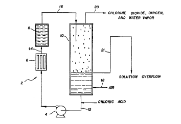
Figure 1 illustrates a flow chart of one
preferred embodiment of the present invention that
utilizes an aqueous chloric acid solution feed
stream, circulation pump, heat exchanger, fixed
catalyst bed, and aqueous chloric acid-chlorine
dioxide gas disengagement zone.
Figure 2 illustrates a flow chart of another
embodiment of the present invention wherein an ~
oxygen-evolving catalyst-containing reaction zone is
mounted in the upper section of gas/liquid dis-
engagement zone or vessel so that an aqueous chloric
acid solution is percolated through the catalyst-
containing reaction zone.
The term "aqueous chloric acid solution" as usedas the chlorine dioxide precursor in the present
specification and claims is intended to mean only
CA 02204899 1997-0~-08
WO96/16897 PCT~S95l15101
--10--
aqueous solutions of pure chloric acid or aqueous
solution mixtures of chloric acid and alkali metal
chlorate where such aqueous solutions are
substantially free of both anionic and cationic
impurities (i.e., contains less than 1.0%,
preferably less than 0.1%, by weight of total
anionic and cationic impurities). The preferred
precursor is aqueous solution of pure chloric acid
in which the concentration of the chloric acid is at
least 5% by weight, more preferably, from about 10%
to about 50% by weight. Alternatively, the chlorine
dioxide precursor may be an aqueous solution of
chloric acid and an alkali metal chlorate in which
the concentration of the chloric acid is at least
about 5% by weight and the mole ratio of chloric
acid to the alkali metal chlorate is from about 1:2
to about 250:1. The preferred alkali metal chlorate
salt is sodium chlorate. It is appreciated that if
an alkali metal chlorate is present in the precursor
solution, amounts of that salt will accumulate in
the reaction system, which will have to be removed
and collected or disposed of. Accordingly, pure
chloric acid solutions are preferred to minimize the
reaction system shutdowns.
As stated above, the process of the present
invention is drawn to the chemical reduction of
chloric acid with water in the presence of an
oxygen-evolving catalyst without the use or addition
of either another acid or an added reducing agent.
The reduction reaction of the chloric acid with
water in the presence of the oxygen evolution
catalyst is believed to be as follows:
CA 02204899 1997-0~-08
W096tl6897 PCrtUS95/15101
2HClO3 + H20 ----~ 2ClO2 + l/202 + 2H20
In using an aqueous chloric acid/alkali metal
chlorate solution as th~eedstock, the chloric acid
reacts and the spent reaction solution is an alkali
5 metal chlorate solution, with a small unreacted
residual amount of chloric acid.
High purity chloric acid solutions can be
produced by the oxidation of high purity
hypochlorous acid solutions. One process suitable
lO for producing the chloric acid solutions heats a
hypochlorous acid solution, containing from about
35g~ to about 60g6 by weight of HOCl, at a temperature
in the range of from about 25~ to about 120~C.
This process is represented by the following
15 reactions (A) plus (B) or their sum which is
reaction (C):
3HOCl ---- ~ HCl03 + 2HCl (A)
2HOCl + 2HCl --- ) 2Cl2 + 2H20 (B)
5HOCl ----~ HCl03 + 2Cl2 + 2H20 (C)
Thermal oxidation of hypochlorous acid takes
place at ambient temperatures and autogenous
pressures. To increase the rate of production of
chloric acid, the reactant may be decomposed at
elevated temperatures. The concentrated
hypochlorous acid solution may be heated at
temperatures, for example, in the range of from
about 50~ tQabout 120~C, and preferably in the
range of from about 70~ to about 110~C to increase
the rate of decomposition of the hypochlorous acid
and hence the rate of production of chloric acid.
-
CA 02204899 1997-0~-08
WO96116897 PCT~S95/15101
-12-
Another process for producing the high purity
chloric acid solution utilizes the anodic oxidation
of the high purity concentrated hypochlorous acid
solution in an electrolytic cell having an anode
5 compartment, a cathode compartment, and a cation _
exchange membrane separating the anode compartment
from the cathode compartment. In operation, the
process includes feeding an aqueous solution of
hypochlorous acid to the anode compartment, and
electrolyzing the agueous solution of hypochlorous
solution at a temperature of from about o~ to about
80~C to produce the chloric acid solution.
The process is represented by the following
reaction:
HOCl + 2H20 ~ HCl03 + 2H2 + 4e~
Chloric acid solutions can be produced by these
processes in any concentrations desired up to a~out
50% by weight of HCl03. However, preferred
concentrations are those in the range of from about
5% to about 45% by weight of HCl03.
Aqueous chloric acid/alkali metal chlorate
solutions are produced by the electrolysis of alkali
metal chlorate solutions. See the above-noted U.S.
patents for preferred processing parameters.
The catalyst employed in the process is named an
oxygen evolution catalyst in this process applica-
tion because the catalytic reaction proceeds in a
manner such that water is a reducing agent for the
reduction of chloric acid to chlorine dioxide and
producing oxygen as a byproduct. Suitable oxygen-
evolving catalysts include, for example, metals and
CA 02204899 1997-0~-08
WO96/16897 PCT~S9S/lS101
-13-
oxides of the elements of Group VIIIA of the
Periodic Table of Elements (Handbook of Chemistry
~ and Physics, 68th Edition, CRC Press, Inc. Boca
Raton, FL, 1978-88, inside cover). Platinum group
metals including platinum, palladium, iridium,
rhodium, and ruthenium; and mixtures or alloys of
these platinum group metals may be employed.
Additionally, oxides of the platinum group metals
such as iridium, rhodium, or ruthenium, as well as
mixtures of these oxides with platinum group metals
or alloys of these platinum group metals could be
suitably employed. Likewise, iron alloys such as
stainless steel, nickel or nickel based alloys, and
cobalt based alloys can be used as oxygen-evolving
catalysts in the process of the invention. Other
oxygen-evolving catalysts include semiconductive
ceramics known as perovskites. The catalyst may be
present as particles suspended in the reaction
mixture or supported on an inert substrate. The
oxygen-evolving catalysts may be used in the form of
a packed bed, slurries, or any structure which will
suitably promote mass transfer and increase reaction
surface area. In a preferred embodiment of this
invention, the catalyst is supported on valve metal
heat exchanger surfaces to facilitate evaporation of
water during the reaction. Suitable valve metals
include titanium, niobium, zirconium, hafnium, and
tantalum, among others.~
The oxygen evolution catalysts can also be mixed
with other metals and oxides either for extending
their surface area or to increase reaction rates and
reactivity. These include the metals and their
oxides above, as well as valve metals such as
CA 02204899 1997-OS-08
W O96/16897 PCTnUS95/lS101
-14-
__
niobium, titanium, aluminum, zirconium, hafnium, and
tantalum. One embodiment is to use the catalysts on
a stable support structure such as acid and oxidizer
corrosion resistant metals such as titanium,
niobium, and zirconium as well as ceramic-type
materials such as alumina, zirconium oxide, silica,
aluminum silicates, various titanium oxides and
titanium suboxides, and natural and synthetic
zeolites among others. Preferred are valve metal
substrates such as titanium, zirconium, or niobium
and valve metal oxide ceramics or glasses such as
those containing an aluminum oxide, zirconium oxide,
or titanium oxide, or mixtures thereof.
Generally, a flowing stream of aqueous chloric
acid solution is heated and then contacted with a
physically separate and hydraulically connected
fixed structure con~t~;n;ng an oxygen evolving
catalyst. The catalyst promotes the chemical
reduction of chloric acid using water as a reductant
to form chlorine dioxide and oxygen gas. The
aqueous mixture of gas and liquid is then stripped
in a separate disengagement zone of chlorine
dioxide, oxygen, and water vapor using an external
air stream at atmospheric or super a~mospheric
pressures or by operating the system at
subatmospheric pressures with an external vacuum
source. The gas stream of chlorine dioxide, oxygen,
and water vapor can then be used in various
applications utilizing gas phase reactions or be
absorbed or dissolved into water for aqueous phase
chlorine dioxide application reactions. The
apparatus is designed for safe system start-ups and
shutdowns. In one embodiment, this is accomplished
. : ~
CA 02204899 1997-0~-08
WO96/16897 PCT~S95/lS101
-15-
by physically separating the catalytic reaction zone
from the aqueous solution/gas disengagement zone.
Preferably, a flowing stream of aqueous chloric
acid solution is heated and then contacted in a
reaction zone containing an oxygen evolving
catalyst. The catalyst promotes the chemical
reduction of chloric acid using water as a reductant
to produce chlorine dioxide and oxygen. The aqueous
mixture of gas and liquid is then stripped of
chlorine dioxide, oxygen, and water vapor using an
external air stream at atmospheric or super
atmospheric pressures or by operating the system at
subatmospheric pressures with an external vacuum
source. The gas stream of chlorine dioxide, oxygen,
and water vapor can then be used in various applica-
tions utilizing gas phase reactions or be absorbed
or dissolved into water for aqueous phase reactions.
The chlorine dioxide generation reaction rate of
chloric acid with the oxygen evolution catalyst is
determined by liquid mass transfer, total chloric
acid concentration, chlorate ion concentration,
catalyst surface area, and solution temperature.
The preferred generator chloric acid solution
operating temperature from about 0~ to 100~C, more
preferably between about 5~ to 90~C, and more-
~preferably from about 10~ to 80~C.
The preferred generator system operating
pressures are from subatmospheric in a range from
about 50-700 mm Hg to super atmospheric operating
pressures ranging from about 1 psig to about 200
psig, preferably from about 1.1 to 100 psig.
When operating under vacuum, the temperature and
pressure are related by the boiling point of the
CA 02204899 1997-0~-08
WO96/16897 PCT~S95/15101
-16-
solution, so that the absolute pressure is regulated
to provide the desired temperature range. When a
supply of air is used to operate at atmospheric and
super atmospheric pressure, the flow rate of air and
the flow of heat determine the partial pressure of
water vapor exiting the generator as well as the
temperature.
Under either atmospheric or subatmospheric
operating conditions, the generation of chlorine
dioxide is slightly endothermic. Heat must be
supplied to the system at a rate sufficient to
provide this heat of reaction in addition to the
heat required to evaporate water contained in the
chloric acid feed and water produced by the chemical
reduction of chloric acid. The precise heat
requirement will be apparent to one skilled in the
art by the need to control the steady state
operating concentration and level of generator
solution.
In one of the more preferred embodiments of this
process, the control of the process can be performed
simply as follows:
l. Air is preheated to a temperature in the
range of about 40~C to about 400~C by means of a
thermostatically regulated heat source. The
temperature of the air determines the outlet
concentration of chlorine dioxide with higher
temperatures producing higher concentrations. An
optional heat sensitive electrical connection to the
heating element can provide a safety limit to assure
that hazardous chlorine dioxide concentrations are
not produced.
.
CA 02204899 1997-0~-08
W096/16897 PCT~S95/15101
2. The flow of air is adjusted to produce the
desired flow rate of chlorine dioxide product.
- 3. Chloric acid feed is added to maintain a
fixed liquid level in the generator.
An additional optional control mPch~n;~m is
desired to assure a safe shutdown of the generator
in the event of a loss of power. A flow of unheated
air through the generator will cool the solution to
a temperature at which production of chlorine
dioxide will stop. Supply of this air can be
provided from a tank of compressed air with a
capacity sufficient to cool the generator. In this
way, unheated air will continue to flow through the
generator even when power is lost sufficient to
prevent accumulation and decomposition of chlorine
dioxide. In addition, a solid absorbent cartridge
can be used to absor-b oxcess chlorine dioxide
produced by the generator on shutdown so that it is
not released.
A unique property of this process is that when
heated air is used, the concentration of chloric
acid in the generator is self-regulating. If the
concentration is too low for chlorine dioxide
generation at the desired rate, water vapor will be
removed by evaporation and the water replaced by
concentrated chloric acid feed until the required
concentration is achieved. If the concentration is
higher than its steady state condition, the chlorine
dioxide production rate will be higher than the rate
of chloric acid addition until the concentration
drops. The self-regulating nature of the generated
chloric acid concentration in this system is a
unique feature of this process.
CA 02204899 1997-0~-08
WO96/16897 PCT~S95/15101
-18-
As stated above, the apparatus of the present
invention has an arrangement design in such that the
catalytic reaction zone is physically separated and
hydraulically connected to the liquid/gas disengage-
5 ment zone. The reaction proceeds only when chloric
acid is pumped or otherwise introduced into the
reaction zone. On shutdowns, the pump is stopped
and the chloric acid solution drains from the
reaction zone lnto the liquid/gas disengagement zone
l0 and the chlorine dioxide generation reaction
essentially stops.
~igure l shows one preferred embodiment of the
general process scheme and apparatus for generating
chlorine dioxide directly from aqueous chloric acid
15 or chloric acid-sodium chlorate mixtures employing
an oxygen evolving catalyst. The apparatus 2
consists of an aqueous chloric acid solution source
(not shown), circulation pump 4, heat exchanger 6,
fixed catalyst bed 8, and gas/liquid disengagement
20 zone l0. In this embodiment, the fixed catalyst bed
8 is physically separate and connected hydraulically
to the gas/liquid disengagement zone l0 using a
suitable vertical height differential from the
liquid level of the chloric acid in the solution/gas
25 disengagement zone.
Chloric acid is pumped or fed from its source
(not shown) into conduit 12 at a rate both to keep
the solution level constant in the gas/liquid
disengagement zone l0 and to supply sufficient
30 reactant to the catalyst bed 8. A motive force r
transporting means such as an eductor may be used
instead of pump 4. The circulation pump 4 on
conduit 12 circulates the chloric acid through a
CA 02204899 1997-0~-08
WO96/16897 PCT~S95/15101
--19--
heat exchanger 6 used to heat the chloric acid to a
suitable temperature such that the reaction of
- chloric acid with the catalyst in the presence of
water in catalyst bed 8 is at a suitable chlorine
dioxide generation rate. The heat exchanger 6 can
use heat provided by any suitable heating source
such as by electrical, steam, or combustion methods.
The heat exchanger 6 can be made from any suitable
chemically compatible metallic, glass, ceramic, or
polymeric materials. Alternatively, a forced heated
air source and an air-liquid mixing zone may be
employed instead of the heat exchanger 6.
The heated solution enters the catalyst bed 8 by
conduit 14 where it reacts to form a two-phase
mixture of chlorine dioxide and oxygen and chloric
acid aqueous solution. The fixed catalyst bed 8
preferably is a substrate structure coated or
covered with catalyst inside a suitable sized
vessel. The substrate is generally made from a
material chemically compatible with chloric acid. It
may be any suitable metal, ceramic, or polymer. The
substrate structure is preferably any suitable
complex 3-dimensional design with a high surface
area so as to increase the contact of the chloric
acid solution with the catalyst impregnated or-
coated on the surfaces of the substrate.
The two-phase gas-aqueous solution that exits the
catalyst bed 8 is transferred by conduit 16 to the
top of the gas/liquid disengager zone lO. The
liquid phase drops down into the solution at the
bottom of the zone lO. Air is introduced by conduit
18 at a suitable point either below the solution
level or above it such that the air dilutes and
-
CA 02204899 1997-0~-08
W O96/16897 PCTrUS95/15101
-20-
transports the chlorine dioxide, oxygen, and water
vapor from the zone 10 through a gas exit line 20.
A solution overflow line 21 iS also provided to help
control the liquid level in the solution/gas
disengagement zone as re~uired by the system during
operation.
Preferably, the oxygen evolving catalyst is
deposited on an open porous three ~;m~n~ional
support made from a chemically resistant metallic or
nonmetallic material. The structure can be mounted
in various locations in the system in the various
embodiments, but basically it is located such that
on system shutdown it self-drains of any chloric
acid solution. The catalyst structure can be of any
suitable size and active surface area such that it
can generate chlorine dioxide gas at rates suitable
for each use application.
Additionally, sections of solution/gas separation
packings made from plastic meshes or commercial
scrubber packings can be mounted in the gas/liquid
separation vessel at strategic locations in order to
provide surface area for the increased efficiency
separation of gases from the liquid.
The volume amount of catalyst coated structure as
a percentage of the total generator volume can range
from 0.01% to 95%, preferably 0.1% to 90%, and more
preferably 0.2% to 80%. The open support structure
can be in the form of saddles, spheres, meshes or
pads, or any form suitable and available in the art
for use in gas-liquid scrubber systems. The
catalyst coated structure can also be located in one
or more areas in the generator.
CA 02204899 1997-OS-08
WO96tl6897 PCT~S95/15101
-21-
Another preferred embodiment is shown by Figure
2. In this embodiment, the catalyst coated
- structure is mounted within the upper section of the
generator solution or gas/liquid separation zone
such that the chloric acid solution is percolated by
various methods through the catalyst bed.
Figure 2 shows an alternative chlorine dioxide
generator apparatus set-up 22 having a separate
catalyst zone 24 located in the same compartment as
the gas/liquid disengagement zone 26 and which is
hydraulically connected to the gas/liquid dis-
engagement zone 26. Chloric acid enters the gas/
liquid disengagement zone by conduit 27. Air is
passed through a heat exchanger 28 and conduit 30 to
lS heat the air to temperatures between about 40~-400~C
and which is introduced into a standpipe 32 in the
generator 22 that is connected into the catalyst-
containing vessel 24 located above the liquid level
of chloric acid in the gas/liquid disengagement zone
compartment 26. The standpipe 32 contains holes 34
located under the chloric acid solution level such
that the flow of air acts as the motive force for
aspirating the chloric acid liquid into the gas
stream. The heated gas stream with chloric acid
then enters into the catalyst bed vessel 24 and
exits out above the catalyst vessel 24 through a
short pipe 36. The catalyst bed 28 preferably
contains a catalyst coating on a high surface area
support structure to increase the area for the
reduction of chloric acid to chlorine dioxide and
oxygen. This set up is similar to percolating
liquid through coffee grinds in a coffee percolator.
This system in Figure 2 also contains a solution
CA 02204899 1997-0~-08
WO96116897 PCT~S9S/15101
-22-
overflow line 38 to allow for the chloric acid
solution level in the generator system to remain
constant in the event that too much chloric acid is
introduced into the generator.
The liquid and chlorine dioxide containing
gaseous products are then separated or disengaged in
the air space above the catalyst vessel. The
chlorine dioxide, water vapor, and oxygen exit the
generator system by conduit line 40, and the spent
chloric acid falls down in the chloric acid solution
located below the catalyst vessel. Optional addi-
tional equipment may be added to the system such as
a demister pad or gas/liquid impingement plate or
hat that is mounted or used above the standpipe
where the gas/liquid exits the catalyst vessel to
minimize liquid entrainment into the gas product
stream. On system shutdown, the chloric acid
solution present in the catalyst bed drains freely
by gravity back into the liquid level in the
liquid/gas disengagement zone of the reactor. The
air line to the generator can be optionally routed
coming in through the top of the generator vessel
and into the bottom of the standpipe so that there
is no bottom connection required to the generator
which may hold chloric acid liquid.
There are numerous other alternative arrangements
or embodiments of contacting a heated chloric acid
solution with the catalyst bed, many of which that
can be designed by those skilled in the art. The
basic feature requirement is that the chloric acid
reactant is heated and is allowed to pass through a
separate catalyst containing bed by some motive
force such as eductor or by a pump or by compressed
CA 02204899 1997-0~-08
WO96/16897 PCT~S95/15101
-23-
air, the spent chloric acid and gaseous products are
separated, and the chlorine dioxide reaction is
stopped by stopping the flow of reactant into the
catalyst bed with the remaining chloric acid in
catalyst bed freely drain-ing out of the catalyst
bed.
In another embodiment, the catalyst coated
structure could be mounted in the piping going to
the top of the scrubber and have the chlorine
dioxide reaction occur in that area. Optionally,
the catalyst coated structure could be so mounted in
the piping arrangement such that a valve could be
opened to allow solution to go through the material
to produce additional chlorine dioxide when it is
required, thus optimizing chloric acid consumption.
The same could be done in the gas disengagement zone
where a device for allowing solution to contact the
catalyst when wanted could be installed.
Other embodiments of the generator design include
(l) the use of a hot air source instead of external
heat to provide the temperature needed for the
reaction to proceed at suitable rates and to provide
the dilution required for the chlorine dioxide as
well as to provide the motive force for pumping/
forcing the chloric acid into the catalyst reaction
zone; and (2) catalyst bed positioned inside
solution/gas disengager wherein the catalyst bed is
positioned in the upper part of the solution/gas
disengager zone or vessel and connected with a pipe
below the chloric acid solution level. A hot air
source is injected into the pipe and pumps the
chloric acid solution through the catalyst bed and
CA 02204899 1997-0~-08
WO96116897 PCT~S95115101
-24-
,, _ . ~
drains back down. No circulation pump is required
in this embodiment.
The following experiments are provided to further
illustrate the present invention. All parts and
percentages are by weight and all temperatures are
degrees Celsius unless explicitly stated otherwise.
EXAMPLE 1
This example shows that a ruthenium oxide
catalyst coated high surface area titanium felt can
produce chlorine dioxide from a heated chloric acid-
sodium chlorate solution without externally added
acid to the solution.
A ruthenium oxide (RuO2) coated catalyst
structure on a titanium fiber felt was prepared for
demonstrating chlo~ne dioxide generation from a
chloric acid-sodium chlorate mixture. A 4 inch long
by 2 inch wide by 0.125 inch thick titanium felt pad
substrate was prepared by compressing 50 gm of 0.002
mil x 0.004 mil melt spun titanium fiber obtained
from Ribbon Technology Inc. (Gahanna, OH) in a steel
die. The compressed fiber was then spot welded in
numerous points to physically bind or hold the pad
together. A ruthenium trichloride solution was then
prepared by dissolving l gm of RUCl3 in 50 ml of
propanol alcohol. The felt pad was heated with a
hot air gun and four aliquots of the solution were
sequentially painted onto the structure and fully
dried. The titanium felt pad was then placed in a
450~C furnace in air for a period of one hour and
then cooled in air to room temperature.
CA 02204899 1997-0~-08
Wo96/16897 PCT~S95/15101
-25-
A chloric acid-sodium chlorate mixture was
obtained from a bench scale Olin SSC~ electrolytic
process cell having with a composition of 18.2%
HCl03 with about 24 wt. % NaClO3. About 400 ml of
the solution was placed in a 500 ml beaker on a hot
plate with a magnetic stirrer. The ruthenium oxide
catalyst coated felt p~d was immersed into the
solution. Oxygen gas bubbles were noted evolving
from the solution in signi~icant amounts starting at
about 30~C with chlorine dioxide noted from the
solution. The solution color also turned to a light
yellow at this temperature indicating chlorine
dioxide in the solution phase. The solution yellow
color and the oxygen generation rate from the
catalyst surface qualitatively increased with the
solution temperature which was stopped at about 60~C
in the experiment.
EXAMPLE 2
A glass apparatus was constructed to demonstrate
the generation of chlorine dioxide by pumping a
heated aqueous chloric acid solution through a
physically separate, but hydraulically connected,
catalyst section consisting of an Ru02 catalyst
coating on an inert high surface area titanium fiber
felt substrate, and then removing the generated
chlorine dioxide gaseous product from the system
with an air stream.
A 500 ml volume 3-neck round bottom glass flask
was fitted with a glass thermometer to measure
chloric acid solution temperature, an air sparge
connection having a ~" TEFLON~ tube routed to the
CA 02204899 1997-0~-08
W O96tl6897 PCTnUS95115101
-26-
inside bottom of the flask, a circulation pump %"
TEFLON tube input feed line routed to the inside
bottom of the flask, and a 24 inch tall vertical
glass piping section having an inside diameter of
about ~" with about a 3 inch length section of the
piping packed with a catalyst, a glass tee located
above the catalyst section where chloric acid is
introduced from the circulation pump, and an exit
point connection on the glass tubing above the
catalyst section where the input air, chlorine
dioxide, oxygen, and water vapor gaseous products
exit the generator system. The catalyst used in the
system was an identical RuO2 catalyst on a titanium
fiber structure as described in Example 1 having a
specific surface area of about 60 cm2/cm3 and density
of 10% (i.e., 90% porosity). A 6 cm width by 4 cm
length of the Ru02 coated felt weighing about 10 gm
was cut into six 1 cm x 4 cm strips that were packed
into the 3-inch long catalyst section in the
vertical glass piping, as described above, having a
total calculated surface area of 45/cm2. The
completed 3-neck round bottom flask Cl02 generator
assembly was mounted on top of a hot plate to supply
heat to the flask.
2 5 The 3-neck flask was filled with about 200 ml of
a 35.2 wt. percent aqueous chloric acid solution
produced from the anodic oxidation of HOCl and
concentrated by vacuum evaporation. A peristaltic
pump was used to continuously pump chloric acid from
the 3-neck flask at a constant rate of 60 ml/min
into the vertical glass pipe section tee above the
catalyst section and drained by gravity from the
catalyst section down into the flask. Air was
CA 02204899 1997-0~-08
WO96tl6897 PCT~S95/15101
-27-
introduced into the chloric acid solution by the ~
inch TEFLON tubing connection into the 3-neck flask
and passed up through the chloric acid wetted
catalyst and out through the top of the vertical
glass section at a constant rate of about 1,200
ml/min to purge the system of the generated chlorine
dioxide and oxygen. The system was heated to
various chloric acid solution temperatures by
adjusting the hot plate settings, and the system was
allowed to come to a chlorine dioxide production
equilibrium.
The system chlorine dioxide generation rate was
measured by directing the gas product stream into a
gas collection bottle containing a pH 7.0 buffered
KI (potassium iodide) solution for a measured time
period. The KI solution was then titrated
iodometrically with~so~;um thiosulfate in a two-step
titration method used for determining chlorine
dioxide and chlorine as given in Standard Methods
for the ~m; nation of Water and Wastewater, 17th
edition. The results are given below in Table 1:
TABLE 1
Measured chlorine dioxide generation rates as a
function of various chloric acid temperatures in the
flask at constant catalyst surface, constant
flowrate through catalyst, and constant air
stripping flowrate.
CA 02204899 1997-0~-08
W O 96tl6897 PCTnUS9511510
-28-
Chloric Acid ClO2 ClO2 C1 in
Solution Production Rate Production Rate C~02
Temp. in ~C in gm/min in gm/hr Product
46 0.0173 1.038 ND
58 0.0356 2.136 ND
0.0617 3.702 ND
71 0.0913 5.478 . ND
The two-step KI iodometric_analytical method
employed showed that chlorine was nondetectable (ND)
in the chlorine dioxide gaseous product stream. The
flowrate of the chloric acid solution was not
sufficient to submerge or wet the entire catalyst
bed with liquid. Increased production rates from
the generator can be achieved by using higher
solution flowrates through the catalyst bed to
increase mass transfer, increasing the catalyst
surface area by employing catalysts with higher
surface areas and increasing the physical catalyst
contact area, and by increasing the solution/system
reaction temperatures up to the limit of chlorine
dioxide decomposition.
While the invention has been described above with
reference to specific embodiments thereof, it is
apparent that many changes, modifications, and
variations can be made without departing from the
inventive concept disclosed herein. Accordingly, it
is intended to embrace all such changes, modifica-
tions, and variations that fall within the spirit
and broad scope of the appended claims.
-