Note: Descriptions are shown in the official language in which they were submitted.
CA 02205094 2005-04-28
.,,
WIRE TENSIONER FOR
DYNAMO-ELECTRIC
MACHINE CCZ,I~ WI2JDER
Background of the Invent~c~,~
This invention relates to manufacturing
equipment for electric machines, and more particularly
to an improved wire tensioner used for winding coils
and for terminating leads of armatures and stators in
dynamo-electric machines such as electric motors.
Although the invention will be described primarily in
the context of its application to electric motor
armatures, it will be appreciated that it is equally
applicable to rotating rotors in general which are
wound with wire for conducting e).ectric current. For
convenience, all such rotors are referred to herein as
armatures. Also, although the invention will be
described primarily in the context of flyer-type
armature coil winders, it will.be understood that the
invention is equally applicable to winders that employ
other types of coil wire dispensing members and to
stator winders (see, for example, Luciani et al. U.S.
patent 4,858,835).
CA 02205094 2005-04-28 y
- 2 -
Flyer-type armature winders for winding coils
in the slots of an armature stack and for connecting
the leads of the coils to nearby bars of the armature's
commutator are well known as shown, for example, by
5 Lombardi et al. U.S. patent 5,257,'l45 and Cardini et
al. U.S. patent 5,383,629. A common problem
associated with these and other traditional flyer-type
winders is instantaneous increases in wire tension
10 during winding which can cause wire breakage. These
increases in wire tension cannot be avoided in
conventional tensioners and present themselves as a
series of peaks with respect to a nominal winding
tension being followed by the tensioner.
15 To reduce the deleterious effects associated
with such wire tension peaks, the nominal winding
tension is preset by an operator during a set-up stage
of the winder to guarantee that the coils being wound
have their turns sufficiently taut and well distributed
20 around the armature's stack, without causing excessive
strain on the wire as a result of the instantaneous
wire tension increases. However, when the operator
sets the tensioner so that the wire does not break
during the instantaneous increases in tension, most of
25 the wire will be wound with a less than optimal tension
level, and the tension peaks will continue to cause
sudden and undesirable strain increases in the wire
being wound.
With traditional tensioners, the start of
30 winding of a coil (when the flyer is reaching its top
speed after having accomplished a lead connection to a
commutator bar) is particularly fraught with
instantaneous increases in wire tension with respect to
the nominal value. If the operator incurs a breakage
- CA 02205094 1997-OS-27
- 3 -
of the wire during this stage, he proceeds to reset the
tensioner to limit the nominal winding tension, and in
extreme cases may even reduce the rotation speed of the
flyers.
The cause of the instantaneous increases in
wire tension is excessive angular movements of the
tensioner's dancer arm produced by a pre-loaded spring.
As is well known, the dancer arm is present in the
tensioner mainly to recover wire (or to maintain
tension on the wire) during lead connection stages when
the drag of a mechanical/electrical brake (also present
in the tensioner) is reduced to favor the required wire
delivery from the flyer. More particularly, during
these stages the dancer arm moves from a normal angular
position which it occupies during winding to a
different angular position which produces an increase
in the wire path to the flyer. This change in angular
position of the dancer arm occurs for a variable time
period during sudden inversions in the flyer rotation,
during opening of the winding chucks for indexing of
the armature, and during manipulation of the wire by
the termination equipment. Without the action of the
dancer arm, these operations would reduce the wire
tension to a point which would make it impossible to
guarantee any further control of the wire.
When winding begins for a successive coil
following lead connection, the dancer arm remains in a
different position with respect to the position it
occupied during winding of the previous coil. Only
after the drag of the mechanical/electrical brake
increases to its nominal level during winding of the
successive coil will the dancer arm attempt to reach
the position it occupied during winding of the previous
coil. Often this position is never reached and the
CA 02205094 1997-OS-27
- 4 -
dancer arm instead experiences high dynamic
oscillations in position. The different positions
occupied by the dancer arm between the winding of
different coils, and the presence of the high dynamic
oscillations, cause the instantaneous increases in wire
tension.
A need therefore exists for methods and
apparatus for reducing instantaneous increases in wire
tension during the winding of armatures. Such methods
and apparatus will reduce detrimental wire tension
variations during winding and will allow the nominal
wire tension to be the optimal wire tension.
In view of the foregoing, it is an object of
this invention to provide methods and apparatus for
reducing instantaneous increases in wire tension during
the winding of armatures.
Another possible problem with spring-loaded
dancer arms is the fact that the nominal position of
the dancer arm tends to be quite different during
different phases of the operation of the winder. For
example, during coil lead connection it is desirable to
have relatively low nominal tension in the wire. This
allows a spring-loaded dancer arm to move to a nominal
position that is very different from its nominal
position during coil winding, when it is desirable to
have relatively high nominal tension in the wire. It
may be difficult to provide a structure which allows
the dancer arm to dance freely about two nominal
positions that are so different from one another. For
example, if the dancer arm spring is adjusted to allow
the dancer arm to dance freely about one of these
nominal positions, then the dancer arm may contact
support structures or other components when it attempts
to dance about its other nominal position.
CA 02205094 2005-04-28
- 5 -
It is therefore another c>bject of this
invention to provide dancer arm or similar wire take-up
mechanisms that do not necessarily have significantly
different nominal positions in response to different
5 nominal wire tensions.
Summary of the Invention
These and other objects of the invention are
accomplished in accordance with the principles of the
invention by providing a tensioner for use in an
10 armature winder which significantly reduces instan-
taneous increases in wire tension during winding and lead
connection. In one embodiment wire from a wire spool is passed
over a hysteresis brake to a flyer arm used to wind
armatures. To properly direct the wire between the
15 wire spool, brake, and flyer arm, a number of pulley
wheels are disposed between these ~~omponents. In
addition to directing the wire, one of the pulley
wheels is coupled to a load cell for monitoring wire
tension, while another of the pulleys is mounted to a
20 first end of a dancer arm. The dancer arm works in
cooperation with the hysteresis brake to regulate the
tension of the wire (as. described below).
The position of the dancer arm (and thus the
tension of the wire to be wound) is controlled with an
25 air cylinder coupled to a second end of the dancer arm
by a mechanical linkage (e.g., a piston shaft and a
hinged connection). By moving the mechanical linkage,
the dancer arm is caused to pivot about a fulcrum axle
so that the first end of the dancer arm moves downward
30 when the mechanical linkage is raised and moves upward
when the mechanical linkage is lo~rered.
To control the mechanical linkage's position,
a piston located within the air cylinder is attached to
CA 02205094 1997-OS-27
- 6 -
the linkage. This piston divides the air cylinder into
a top air chamber disposed between the piston and the
top of the air cylinder, and a bottom air chamber
disposed between the piston and the bottom of the air
cylinder. By regulating the pressure in the top air
chamber, the piston (and thus the mechanical linkage)
may be raised or lowered, causing the first end of
dancer arm to be reciprocally lowered or raised.
Accordingly, if the drag of the hysteresis brake is
kept constant, the wire's tension will be decreased
when the first end of the dancer arm is lowered or
increased when the first end of the dancer arm is
raised. The air pressure within the top air chamber is
regulated by a closed-loop proportional valve connected
to the top air chamber through a flow valve. This flow
valve helps to dampen the movement of the dancer arm.
System controls are provided which regulate
the drag of the hysteresis brake, which monitor the
wire's tension via the load cell, and which control the
pressure within the top air chamber of the air cylinder
(to maintain the dancer arm within a proper position
range delimited by a first and a second limit sensor
coupled to the system controls). Additionally, the
system controls monitor wire breakage via a wire
breakage detection device (as described below).
In operation, during a lead connection stage
of the winder, a low pressure is supplied to the top
air chamber of the air cylinder and the drag of the
hysteresis brake is reduced (both via commands from the
system controls) so that the dancer arm may be raised.
This may help maintain sufficient wire tension for the
lead connection process. Following lead connection,
the winder transitions to a winding stage. During this
transition (as well as during the winding stage) a high
CA 02205094 1997-OS-27
pressure is supplied to the top air chamber of the air
cylinder and the drag of the hysteresis brake is
increased. This may lower the dancer arm for the
winding process. Following the winding operation, the
flyer arm decelerates so that another lead connection
may be made. During flyer arm deceleration, the top
air chamber pressure is reduced prior to reducing the
drag of the hysteresis brake so that the dancer arm
maintains its proper position during the deceleration
process. Once the flyer arm has decelerated, the drag
of the hysteresis brake is reduced as required for lead
connection.
As an alternative to raising or lowering the
dancer arm for various phases of the operation, the
pressure in the air chamber may be adjusted to keep the
dancer arm in approximately the same nominal position
during various phases, despite significantly different
nominal wire tension (produced by the hysteresis brake)
in those various phases.
During all winder stages, the pressurized air
within the top air chamber opposes sudden changes in
dancer arm position in a controlled manner, and dancer
arm position is maintained within the position range
delimited by the limit sensors through modulation of
the closed-loop proportional valve by the system
controls. For example, if either limit sensor detects
the dancer arm, the system controls may issue a command
instructing the closed-loop proportional valve to
supply more or less pressure to the top air chamber so
that the position of the dancer arm is adjusted
accordingly. The flow valve disposed between the
closed-loop proportional valve and the top air cylinder
dampens oscillations in the position of the dancer arm.
CA 02205094 1997-OS-27
g _
Accordingly, the tensioner of this invention
reduces instantaneous increases in wire tension which
usually occur in traditional flyer winders during
winding and lead connection and which cause wire
breakage. By lowering these tension peaks, the nominal
tension used to wind armatures may be increased and
higher winding speeds may be used. The ability of the
tensioner of this invention to lower tension increases
at the start of winding (when the flyer is reaching its
top speed after having accomplished a lead connection
to a commutator bar) is particularly useful as
instantaneous tension increases are especially
prevalent during this stage in the tensioner's
operation.
In addition to reducing instantaneous wire
tension increases, the present invention decreases
winder down-time associated with wire breakage by
including a wire breakage detection device. If wire
breakage is detected by the system controls, a rapid
discharge valve disposed between the top air chamber of
the air cylinder and the closed-loop proportional valve
quickly depressurizes the top air chamber. Flyer arm
rotation is concurrently halted. In this manner, after
wire breakage, winder operation rapidly ceases prior to
the wire becoming unthreaded from the flyer arm. This
allows winder operation to be restored faster than is
possible.with traditional winders which become
unthreaded following wire breakage.
In another aspect of the invention, dancer
arm position measured during a previous winding
operation is used to adjust dancer arm position during
a current winding operation. For example, limit
sensors may provide the system controls with
information regarding the number of times and/or the
CA 02205094 1997-OS-27
- 9 -
duration that the dancer arm contacts each limit sensor
during a winding operation. This information may then
be stored by the system controls and used during a
subsequent winding operation to control the actuator so
as to optimize dancer arm position (i.e., to minimize
the number of times and duration that the dancer arm
contacts each limit sensor during winding). More
generically, an actuator for applying a force to a
take-up member to influence the position of the take-up
member is provided, along with system controls for
controlling the actuator in response to the take-up
member's position during a previous winding operation.
In general terms the invention provides
apparatus for tensioning wire passing along a path from
a wire source to a wine dispenser in a coil winding
machine. The apparatus includes a take-up member for
contacting the wire between the source and the
dispenser and being movable to change the length of the
path of the wire between the source and the dispenser.
The apparatus further includes a pneumatic actuator for
applying a force to the take-up member to influence the
position of the take-up member, the force being
influenced by pneumatic pressure in the actuator. The
apparatus still further includes a pneumatic system for
controlling the pneumatic pressure in the actuator in
response to a predetermined operating parameter of the
coil winding machine. Examples of such operating
parameters include the current operating phase that the
winder is in (e. g., lead connection phase or coil
winding phase), the current tension of the wire in the
winder, the past history of movements of the wire take-
up member (e. g., most recent contact with a limit
sensor, average position during a recent coil winding
operation, or history of contacts with limit sensors
CA 02205094 1997-OS-27
- 10 -
-. during a recent coil winding cycle), status of wire
(e. g., whether the wire is broken or not), winder
speed, winder acceleration/deceleration, etc.
Further features of the invention, its nature
and various advantages, will be more apparent from the
accompanying drawings and the following detailed
description of the preferred embodiments.
Brief Description of the Drawings
FIG. 1 is a schematic diagram of illustrative
wire tensioner apparatus constructed in accordance with
this invention.
FIG. 2A is a timing diagram of drag force
during a lead connection stage, a winding stage, and a
subsequent lead connection stage for a hysteresis brake
used in the tensioner of FIG. 1.
FIG. 2B is a timing diagram of top air
chamber pressure during a lead connection stage, a
winding stage, and a subsequent lead connection stage
for an air cylinder used in the tensioner of FIG. 1.
FIG. 3 is a schematic diagram of a first
embodiment of a wire breakage detection device used in
the tensioner of FIG. 1.
FIG. 4 is a schematic diagram of a second
embodiment of a wire breakage detection device used in
the tensioner of FIG. 1.
Detailed Description of the Preferred Embodiments
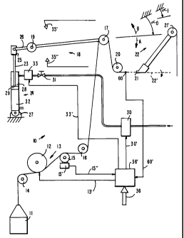
FIG. 1 shows a schematic view of a
tensioner 10 made in accordance with this invention
with wire running from a wire spool 11 to a first
pulley wheel 12 of a hysteresis brake 13. A second
pulley wheel 14 changes the direction of the wire so
that it reaches first pulley wheel 12 of hysteresis
CA 02205094 1997-OS-27
- 11 -
brake 13 at a certain angle. The drag of hysteresis
brake 13 is controlled by a command signal sent over
brake bus 13' as described further below. After first
pulley wheel 12 of brake 13, the wire runs on a third
pulley wheel 15 connected to a load cell 15', load cell
15' measuring the tension being applied to the wire and
outputting this information over a tension bus 15".
From third pulley wheel 15 the wire is directed by a
fourth pulley wheel 16 to a fifth pulley wheel 17 of a
dancer arm 18, dancer arm 18 pivoting on a fulcrum
axle 19. From fifth pulley wheel 17 of dancer arm 18,
the wire travels over a sixth pulley wheel 20 which
aligns the wire with an inlet 21 of a flyer arm 22.
Once the wire has reached inlet 21, it travels through
flyer arm 22 to a seventh pulley wheel 21' (or some
other smooth running surface) integral with flyer arm
22 which delivers the wire to an armature (not shown).
To deliver wire to the armature, flyer arm 22 rotates
around axis 22'.
To control the tension of the wire, dancer
arm 18 is connected to shaft 23 of an air cylinder 24
by means of a first hinged connection 25 coupled to a
counter-lever extension 26 (of dancer arm 18). Air
cylinder 24 comprises a hollow cylinder containing a
top air chamber 28 (disposed between a top of air
cylinder 24 and a piston 29) and a bottom air chamber
32 (disposed between a bottom of air cylinder 24 and
piston 29). The bottom end of air cylinder 24 is
hinged by means of a second hinged connection 27
coupled to the frame of tensioner 10. Top air
chamber 28 is fed with air (traveling through a flow
valve 31 and a rapid discharge valve 33) from a closed-
loop proportional valve 30 which regulates the pressure
in top air chamber 28 in response to electric command
CA 02205094 1997-OS-27
- 12 -
signals sent along control line 30' from system
controls 36'. These command signals cause closed-loop
proportional valve 30 to modulate (i.e., open and
close) to achieve the required pressure in top air
chamber 28 with extreme precision. Closed-loop
proportional valve 30 is preferably a conventional
pneumatic valve which receives a command signal (via
control line 30') with a voltage that is proportional
to a desired output air pressure from closed-loop
proportional valve 30. Closed-loop proportional
valve 30 monitors its actual output air pressure with a
pressure transducer (not shown), and produces an error
signal proportional to the difference between the
desired and actual output pressures. This error signal
is used to modulate closed-loop proportional valve 30
in such a way that the error signal is minimized,
thereby making the actual output pressure substantially
equal to the desired output pressure.
Flow valve 31 intersects the air supply
between closed-loop proportional valve 30 and top air
chamber 28, and the setting of this flow valve is very
important for dampening dynamic oscillations of dancer
arm 18. By somewhat restricting air flow between
closed-loop proportional valve 30 and air cylinder 24,
flow valve 31 beneficially slows down the response time
of air cylinder 24 to changes in air pressure from
closed-loop proportional valve 30 (thereby dampening
movements of dancer arm 18). Flow valve 31 may be a
manually adjustable valve as only infrequent
adjustments to flow valve 31 should be needed. For
example, it may be possible to adjust flow valve 31
during initial construction and testing of tensioner
10, and to thereafter operate the system without
further adjustment of this valve.
CA 02205094 1997-OS-27
- 13 -
Rapid discharge valve 33, located between top
air chamber 28 and flow valve 31 (and controlled via
command signals sent over rapid discharge bus 33' by
system controls 36'), is needed for reasons which will
be explained more fully below.
When air pressure is developed in top air
chamber 28 by closed-loop proportional valve 30, any
tendency of dancer arm 18 to rotate in direction A to
supply more wire to flyer arm 22 (in other words, to
respond to a sudden increase in the wire tension)
becomes opposed in a controlled manner by the pressure
present in top air chamber 28. For the opposite
situation, when there is a decrease in wire tension,
any tendency of dancer arm 18 to rotate in direction B
is facilitated and controlled by the air pressure in
top air chamber 28 and by the lack of air pressure in
bottom air chamber 32 (as bottom air chamber 32 is kept
permanently in a discharge condition toward ambient
pressure).
FIGS. 2A and 2B are timing diagrams of the
drag force applied by hysteresis brake 13 and the
pressure applied to top air chamber 28 (of air cylinder
24 by closed-loop proportional valve 30) during various
stages of tensioner 10's operation, respectively. As
depicted in FIGS. 2A and 2B, stage 2' (the time period
between times To and T1) represents a lead connection
stage of the winder, stage 2 " (the time period between
times T1 and T2) represents a winding stage of the
winder, and stage 2 " ' (the time period between times T2
and T3) represents an immediately successive lead
connection stage of the winder. With reference to
these graphs, tensioner 10 of the invention is set so
that closed-loop proportional valve 30 supplies a low
and constant pressure P1 to top air chamber 28 during
CA 02205094 1997-OS-27
- 14 -
lead connection stage 2'. At the same time hysteresis
brake 13 applies a low drag force Fl. Both the drag of
hysteresis brake 13 and the pressure in top air
chamber 28 are set via command signals from systems
controls 36' (the drag of hysteresis brake 13 being
adjusted by a command signal sent over tension bus 13'
and the pressure of top air chamber 28 being regulated
by a command signal sent over control line 30'). With
these settings, dancer arm 18 moves from an angular
position ao which it occupied during winding to an
angular position al so that sufficient wire tension is
maintained during lead connection operations. If
desired, al can be relatively close to or even
substantially equal to ao.
At the start of the acceleration ramp (time
T1) whereby flyer arm 22 reaches its top speed for
winding a subsequent coil, both the drag of hysteresis
brake 13 and the pressure in top air chamber 28
increase to F2 and P2, respectively, so that dancer arm
18 returns to angular position ao. Dancer arm 18
returns to the ideal angular position ao for winding
without excessive dynamic oscillations because of the
well controlled pressure in top air chamber 28 and the
setting of flow valve 31. In this way the harmful
tension increases described previously are
significantly reduced. To maintain dancer arm 18 in
position ao during deceleration of flyer arm 22 from the
winding speed, the pressure in top air chamber 28 is
lowered to value P1 at time T* (the beginning of flyer
arm 22's deceleration ramp) prior to lowering the drag
of hysteresis brake 13 to drag force F1 as required in
the successive lead connection stage 2 " '.
CA 02205094 1997-OS-27
- 15 -
- In considering the achievements of this
invention, it is important to note that the constant
pressure applied to top air chamber 28, both during the
lead connection stage and during winding, makes dancer
arm 18 more stable throughout all the related
operations of the winder. That is, even the less
detrimental tension variations generated by traditional
tensioners are reduced. Furthermore, the presence of
modulating closed-loop proportional valve 30 guarantees
fast and precise achievement of pressures in top air
chamber 28, thereby reducing oscillations in the
position of dancer arm 18. In addition, use of
proportional valve 30 allows extremely rapid and
precise set up of tensioner 10 by simply keying in
input values 36 to the system controls 36'.
To further control the position of dancer arm
18, a first limit sensor 35' and a second limit sensor
35" monitor when dancer arm 18 moves out of an angular
position range (which these sensors delimit) on either
side of normal angular position a0 and notify system
controls 36' accordingly via a limit bus (not shown)
connected between sensors 35', 35" and system
controls 36'. (Limit sensors 35' and 35" may be, for
example, limit switches which are activated when
contacted by dancer arm 18.) If during winding,
sensors 35', 35" signal that dancer arm 18 is beyond
the range which they delimit, then closed-loop
proportional valve 30 increases or decreases the
pressure of the air going to top air chamber 28
(depending on which sensor has been activated) so that
dancer arm 18 returns within the delimited range. A
program in system controls 36' of tensioner 10 is used
to make this determination and to command closed-loop
CA 02205094 1997-OS-27
- 16 -
proportional valve 30 accordingly. An operation of
this type is particularly necessary when the drag
conditions of tensioner 10 change for reasons unrelated
to tensioner 10's usual operation (e.g., changes in
friction of the pulley wheels, temperature changes of
hysteresis brake 13, or after the settings of tensioner
have been altered). Maintaining dancer arm 18
within the range delimited by sensors 35', 35" avoids
great excursions in the angular position of dancer
10 arm 18 which could bring dancer arm 18 into abutment
with the surrounding structure. It also guarantees
that dancer arm 18 remains very near to the ao angular
position which develops correct tensioning as described
above.
System controls 36' of tensioner 10 may also
be programmed to check limit sensors 35', 35" for the
position of dancer arm 18 at every start of the winder
after the winder has been inoperative for long time
periods. Inoperative conditions tend to change the
drag of hysteresis brake 13 and the friction of the
pulley wheels, at least during a first period of
operation of the winder. Therefore, dancer arm 18 may
be beyond the range delimited by first limit sensor 35'
and second limit sensor 35". Consequently, system
controls 36' may be further programmed to alter the
pressure of top air chamber 28 to bring dancer arm 18
within the required range right from the first period
of operation of the winder.
In another aspect of the invention, system
controls 36' use dancer arm 18 position information
measured during a previous winding operation to adjust
the position of dancer arm 18 during a current winding
operation. This dancer arm 18 position information may
- CA 02205094 1997-OS-27
- 17 -
include the number of times and/or the duration that
dancer arm 18 contacted limit sensor 35' and limit
sensor 35" during the previous winding operation. The
position information may be stored by system controls
36' or by some other storage means and used to optimize
the position of dancer arm 18 via closed-loop
proportional valve 30 (so as to minimize the number of
times and the duration that dancer arm 18 contacts
either limit sensor 35' or limit sensor 35").
Optimized dancer arm 18 position ensures correct wire
tensioning during winding.
In addition to reducing instantaneous
increases in wire tension, the present invention
reduces winder down-time should wire breakage
nonetheless occur. A wire breakage detection device 39
(described below with reference to FIGS. 3 and 4)
detects wire breakage and signals system controls 36'
of the breakage. System controls 36' then cause (via
rapid discharge bus 33') rapid discharge valve 33 to
discharge the pressure in top air chamber 28 extremely
rapidly, and concurrently cause flyer arm 22 to stop
rotating. By doing this, any further oscillation of
dancer arm 18 about position ao is reduced and a
withdrawal of the wire passing through flyer arm 22 due
to the wire breakage can be avoided. In this way,
after a wire breakage, an operator will find the wire
still threaded through flyer arm 22 so that the down
time required to reset the winder is minimized. In
contrast, with traditional tensioners, wire breakage
causes the dancer arm to rotate suddenly in direction B
due to the motivation of a pre-loaded spring. This can
cause the wire to withdraw from the flyer arm and may
even cause the wire to run off the pulley wheels of the
CA 02205094 1997-OS-27
- 18 -
tensioner. Either scenario obviously requires lengthy
intervention by the operator to restore the tensioner
to its working condition.
FIG. 3 shows a wire breakage detection device
S 39 which is able to rapidly determine when a wire
breakage occurs and to signal such an occurrence to
system controls 36' of tensioner 10. System
controls 36' may in turn cause rapid discharge valve 33
to rapidly discharge top air chamber 28 as previously
described.
Referring to FIG. 3, a ceramic head 40' of a
microphone 40 acts as a running surface for the
wire (wire 9 in FIG. 3) traveling from wire spool 11 to
flyer arm 22. Microphone 40 produces a sound signal
which corresponds to the noise produced by the wire
running on ceramic head 40'. This sound signal is fed
to and analyzed by circuitry 41. Circuitry 41 includes
a gain amplifier 42 for amplifying the sound signal
produced by microphone 40, a band-pass filter 43 for
excluding background noises from the amplified sound
signal, and a rectifier 44 for rectifying the filtered
sound signal to produce a "converted" sound signal.
From rectifier 44, the converted sound signal enters a
comparison unit 45 which compares the converted sound
signal to a reference sound signal 46 and produces an
error signal 47 based on the comparison. Reference
sound signal 46 corresponds to a converted sound signal
produced by a wire running perfectly on ceramic
head 40' of microphone 40.
Error signal 47 is output to system
controls 36' of tensioner 10 which trigger rapid
discharge valve 33 (as described previously) if a wire
breakage is detected. That is, if error signal 47
exceeds a certain limit, system controls 36' of
CA 02205094 1997-OS-27
- 19 -
tensioner 10 trigger the discharge of top air chamber
28 by rapid discharge valve 33 and stop flyer arm 22 in
order to avoid a sudden oscillation of dancer arm 18
which would withdraw the wire from flyer arm 22 and
cause the wire to run off the pulley wheels of
tensioner 10.
FIG. 4 shows a second embodiment for a wire
breakage detection device which may be used with
tensioner 10. In this embodiment, an antenna 50 with
antenna arms 50' partially surrounds the running
wire 9. As wire 9 runs within the area between antenna
arms 50', an electrical "pick-up" signal is produced
via electrostatic generation. Wire breakage can be
detected because the electrostatic generation resulting
when wire 9 runs through antenna arms 50' is different
from the electrostatic generation resulting when the
wire is stationary or missing. Circuit 51, which is
very similar to circuit 41 (similar components are
referenced with the same second digit), amplifies the
pick-up signal with an amplifier 52, filters the
amplified pick-up signal with a band-pass filter 53 (to
eliminate electrostatic disturbances picked up by
antenna 50), and rectifies the filtered, amplified
pick-up signal with a rectifier 54 to produce a
"converted" pick-up signal. This converted pick-up
signal then enters a comparison unit 55 which compares
the converted pick-up signal to a reference pick-up
signal 56 and produces an error signal 57 based on the
comparison. Error signal 57 is then fed to system
controls 36' which may trigger rapid discharge valve 33
when there is a drop in the signal produced by antenna
50 (due to a wire breakage). Note that either
microphone 40 or antenna 50 may be placed in a
CA 02205094 1997-OS-27
- 20 -
.. position 60 (FIG. 1) to detect a wire breakage when
using tensioner 10.
It will be understood that the foregoing is
only illustrative of the principles of this invention,
and that various modifications can be made by those
skilled in the art without departing from the scope and
spirit of the invention. For example, while closed-
loop proportional valve 30 is preferably a pneumatic
valve, any other flow control valve or mass flow
controller may be similarly employed. Other valves
types may also be used for flow valve 31 and rapid
discharge valve 33. Further, system controls 36' may
be embodied in hardware, software, or some combination
thereof. Limit sensors 35' and 35 " may take many
forms including switches, motion sensors, or any other
position monitoring means, and a wide variety of wire
breakage detection devices may be used for wire
breakage detecting device 39. As an alternative to
limit sensors 35' and 35", other types of position
sensors may be used. For example, photo-electric cells
may detect various positions of dancer arm 18, or a
linear or rotary potentiometer may be operated by the
dancer arm to provide a more continuous output
indication of dancer arm position. While the use of a
pneumatic actuator for controlling dancer arm 18's
position is preferred, any other actuator (e.g., an
electromagnetic actuator) may be similarly employed and
similarly controlled by system controls 36'.