Note: Descriptions are shown in the official language in which they were submitted.
CA 02205196 1997-OS-13
SINK MOUNTED WATER AGITATION
FIELD OF THE INVENTION
The invention relates to household and
institutional sinks used in cleaning flatware,
kitchenware and dishware. The sink can comprise one two
or more bowls in a sink unit. Each bowl can have
sufficient capacity to hold a significant quantity of
water or aqueous cleaning liquid and flatware, dishware
or kitchenware. The sink can also comprise cleaning
apparatus or a chemical dispenser.
BACKGROUND OF THE INVENTION
Although kitchen sinks have been used in a variety
of environments including household, hotels,
restaurants, hospital food service, military food
service and other places, sinks commonly have not been
used actively as a power driven cleaning station. Most
commonly, such sink installations have been used for
static soaking or handwashing ware. Such sinks are
provided with two, three or more bowls in which kitchen
personnel soak kitchenware and dishware in water for the
purpose of softening food soils for later hand or
automatic machine cleaning. Commonly, pot and pan soak
chemicals, dish soap compositions, etc., can be added to
the water to aid in typically static soaking of food
soils.
One device known as the POWER SOAKS system is known
comprising an installation that is distributed as a
single unit comprising a three bowl sink assembly having
a pumped top to bottom pattern. In the POWER SOAKS, the
circulation of water or aqueous cleaner in a liquid
CA 02205196 1997-OS-13
contents of the sink is withdrawn from an intake
installed in an arbitrary location in the sink or bowl.
Water is drawn from the intake through the pump and then
is directed through nozzles installed on the upper
interior portion of the sink or bowl at or just below
the liquid surface forcing the aqueous solution in a top
to bottom circulation pattern. The POWER SOAKS
apparatus is manufactured as a single unit and cannot
easily be disassembled and retrofitted to existing sink
units. Further, we have found that the horizontal top
to bottom circulation pattern of the POWER SOAKS is not
an optimal pattern for soil softening or removal.
Accordingly, a substantial need exists for a device
that can act to circulate water within a bowl in an
optimal pattern. Further, the apparatus should be
easily retrofitted to common sink installations in both
household and institutional cleaning environments.
BRIEF DISCUSSION OF THE INVENTION
We have found that the optimal circulation pattern
for an agitated cleaning solution in a bowl in a sink
involves moving the solution in a horizontal pattern
with a swirling or cyclonic motion formed around the
center of the sink. Such a horizontal circulation can
provide movement of the aqueous cleaning medium
contained within the sink against food soils formed on
both the interior and the exterior of flatware,
kitchenware and tableware contained within the sink
medium. Further, the horizontal circulation formed
around the bowl can also cause a cyclonic movement of
the ware resulting in a tumbling or other complex motion
2
CA 02205196 1997-OS-13
or circulation of the ware in the swirling stream of the
aqueous medium. Such an energetic motion provides a
superior cleaning environment for kitchenware and
tableware.
Such a motion can be produced in both households or
institutional sinks adapted to cleaning with an
apparatus designed and engineered to form an agitated
aqueous cleaning medium. The sink can contain one or
more bowls each having a liquid capacity of up to 200
liters of aqueous liquid medium or more. The bowl can
have a drain (i.e.) a simple circular aperture for the
passage of liquid and any solids, liquids or dissolved
solids, formed in a lower portion of the bowl. A waste
line can be in liquid communication with the drain which
directs liquid contents to municipal sewer disposal. A
pump can be installed in liquid communication with the
waste line such that the water or aqueous cleaner can be
removed from the waste line downstream from the drain
and, be returned to the bowl or sink. The pump draws
the aqueous medium from the waste line and returns it to
the bowl through liquid outlet means installed in the
base of the bowl that causes the aqueous medium from the
pump to swirl in a horizontal flow with sufficient
energy to tumble the dishware and kitchenware or cause
the ware to move in a complex motion within the sink.
3
CA 02205196 1997-OS-13
The aqueous cleaning medium held in the sink can
comprise a major proportion of an aqueous medium such as
service water derived from the local water utility
containing a minor, but important cleaning proportion of
a cleaning material selected from the group consisting
of a surfactant, a solvent, an acid, a base, a bleach or
compatible mixtures thereof. The pump used in forming
the horizontal circular motion of the water can be a
pump with a power output of about 0.25 to 4 HP or more
having a pump output capacity of about 70 - 1250 liters
of water per minute and preferably, can have a power
output of between 0.5 and 2 horsepower. The pump can be
a centrifugal pump having vanes that can drive the water
energetically through the agitation means.
Further, the sink of the invention can have an
apparatus cooperatively installed in the drain and
adapted to returning the aqueous cleaning medium under
pressure to a collar or other aqueous return that can
direct the flow of the aqueous medium in a horizontal
circular path around the inside of the bowl.
Preferably, the drain has an annular collar or housing
comprising a central waste line and an annular return.
Aqueous medium driven by the pump passes into the
annular collar or return. Water is forced through the
return into the sink in a path that surrounds the drain
and waste pipe. At the point of entry into the sink,
the flow of aqueous medium contacts a stator portion of
the annular collar or housing that forces the liquid to
take a circular path horizontally in this bowl. The
waste line is valved to hold the aqueous medium within
the bowl return and pump mechanism when circulation is
4
CA 02205196 1997-OS-13
desired. The pump takes aqueous cleaning media from the
waste line upstream from the valve. When the pump is
activated, aqueous medium is pumped through the stator
into the sink forming a continuous horizontal circular
or swirling motion that softens and aids in soil removal
and also can cause a tumbling or agitation of the
dishware and tableware in the sink.
Further, the apparatus can also contain a heater
which can increase the temperature of the aqueous medium
to improve action on the soil. Further, the sink of the
invention can have a chemical dispenser installed on the
sink to direct cleaning chemicals into the sink or into
the lines to or from the pump. For the purposes of this
application, the term "return" relates to a device that
acts as a point of release of the water or aqueous
medium while at the drain portion of the sink bottom.
BRIEF DISCUSSION OF T$E DRAWI
Figures 1 and 2 are cross-sectional drawings
illustrative of the operation of the invention. Figure
1 shows a sink with a drain and drain installed central
waste line having water drawn from the waste line into
the pump and then to the annular cyclonic return
installed in the drain. The pump derives water from the
central waste line and returns it through the annular
return causing the preferred horizontal circular motion.
Figure 2 shows an open waste line permitting any liquid
contents of the apparatus to drain to municipal sewage
treatment.
Figure 3 is a view of the sink of the invention
having a screen installed over the drain preventing
5
CA 02205196 1997-OS-13
entry of large waste objects into the waste line. Such
objects could block the proper movement of water through
the drain into the pump and return into the sink.
Further, the pump contains cutting blades that rapidly
and substantially comminute any particulate matter that
passed from the drain into the pump. The particle size
of the waste matter can be reduced substantially in this
operation.
Figure 4 is an isometric view of an installation of
a preferred apparatus of the invention. The figure
shows the drain installed in the sink and the waste
line. Water from the waste line is drawn into the pump
and is directed to the return for cyclonic horizontal
agitation.
Figure 5 is a partial cross-section of the combined
waste line/annular cyclonic return apparatus of the
invention installed in the drain. The figure shows the
central waste line, the annular return and the flow
members creating the cyclonic flow.
Figure 6 is an exploded revealed view of the
assembly of the apparatus of Figure 5.
The figures further show an in-line heater to heat
the aqueous liquid, a stator, veins or blades that can
redirect the flow of the aqueous medium into a circular
pattern. Lastly, the drawings show an offset drain that
can be common in certain installations.
6
CA 02205196 1997-OS-13
DETAITED DISCUSSION OF THE INVENTION
The sink of the invention can have one, two, three
or more bowls that can contain a volume of aqueous
cleaning medium. Such bowls can have a capacity of up
to 200 liters or more depending on the installation
location. The bowls can have a cubic shape, can be
rectangular, can be oval, can be cylindrical or any
other shape that can be manufactured in the form of a
sink. The sink can be manufactured from a variety of
materials including stainless steel, composite materials
made from thermoplastic and fiber reinforcement, ceramic
materials, porcelain, porcelain-coated iron or steel
sinks or other common materials useful in sink
construction.
In the bowl of each sink of the invention is a
drain. The term "drain" is intended to indicate simply
an aperture that typically takes the form of a circular
opening that can permit the aqueous contents of the sink
to be directed to a waste line. Such drains have
conventional diameters (commonly 3.5") adapted to fit
standard plumbing hardware leading to the waste lines.
The invention involves in one embodiment, altering the
plumbing hardware leading to the waste line such that
aqueous cleaning means can be withdrawn from a waste
line using a pump. The aqueous medium drawn by the pump
is then directed through a line back into hardware
installed in the drain such that the aqueous medium is
directed through a return such that the flow is directed
into the sink in a horizontal, circular or swirling
pattern. Such sink hardware can be made from common
7
CA 02205196 1997-OS-13
plumbing materials including metallic plumbing
apparatus, plastic drain material such as ABS
(acrylonitrile-butadiene-styrene) butylene polymers,
plastics or other metal or plastic materials approved
for use in such drain locations.
The pump useful in the sink installations of the
invention is a pump having a capacity of about 75 to
1000 gallons per minute having an energy output of 0.25
to 4 horsepower. Typically, the pumps are electrically
driven but can be driven by a variety of systems. In
the preferred mode of operating the apparatus of the
invention, the waste line is valved such that when the
pump is initiated, the valve is closed holding the
aqueous medium within the system comprising sink or bowl
pump, stator and appropriate lines. The aqueous medium
is drawn from the waste line upstream of the valve into
the pump and is then directed back into the base of the
sink through the drain return or stator apparatus in a
horizontal swirling motion. The aqueous cleaning medium
in the sink can be heated at any place in the sink or in
the apparatus, lines or pump. One preferred location of
a heater is an in-line heater in the line conveying
aqueous medium from the waste line to the pump or
installed in the line from the pump returning water to
the sink. Alternatively, the heater can be installed in
the base of the bowl or in the bowl side. Further, the
bowl can have a chemical dispenser installed such that
cleaning compositions can be introduced into the aqueous
medium in the bowl or through the lines during pump
operation.
8
CA 02205196 1997-OS-13
DETAILED DISCUSSION OF THE DRAWINGS
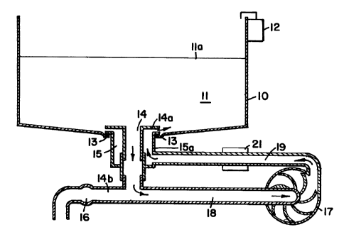
Figure 1 is a cross-sectional representation of the
apparatus of the invention. In Figure 1 a sink bowl 10
contains a volume of water or an aqueous cleaning medium
or solution 11 defined by the liquid surface lla. Such
an aqueous cleaning medium can be formed by introducing
a volume of water into the bowl 10 augmented by
chemicals delivered into the bowl by dispenser 12. The
volume of water or aqueous cleaning medium 11 in the
bowl is added to sufficient capacity to substantially
cover or include any dishware, kitchenware, tableware or
other object requiring cleaning in the bowl 10. In the
base of the bowl is a drain 13 comprising a generally
circular drain opening (commonly about 3.5 inches in
diameter). Such a drain 13 is a standard size common in
sinks and bowls used in food preparation, kitchen and
warewashing operations. Installed in the drain 13 is an
apparatus including a central waste line 14 and an
annular return 15. In operation, the water or aqueous
cleaning medium 11 enters the drain 14 and if valve 16
is closed, can flow only to pump 17 wherein the water or
aqueous cleaning medium is directed to return 15.
Return 15 is configured such that the flow of water or
aqueous cleaning medium exiting return 15 forms a
cyclonic horizontal agitation pattern causing water or
aqueous cleaning medium to contact kitchenware,
tableware or other soiled ware with the aqueous cleaning
medium in a highly effective energetic tumbling motion.
In Figure 1; the waste line 14 is a central drain having
an annular return housing 15a, surrounding the central
waste line 14. The waste line/return apparatus is made
9
CA 02205196 1997-OS-13
from a cylindrical portion that is cooperatively
attached in fluid communication with the waste line 14b,
the liquid conduit 18 to the pump 17 and the liquid
conduit 19 from the pump 17 to the return 15. The
apparatus has an circular cylindrical/central portion
14a which partially defines the waste line and the
horizontal cyclonic return path. When the pump 17 is
energized, water is drawn from the waste line 14 through
line 18 and to pump 17 wherein the water is then
returned under pressure through line 19 into the return
to create a highly energetic cyclonic agitation and
flow. An in-line heater 21 is installed to heat water
flowing in line 19.
Figure 2 is a cross-sectional diagram of the
15 apparatus of the invention showing the operation of the
apparatus when valve 16 is open and pump 17 is not in
operation, permitting flow of water or aqueous cleaning
medium from the bowl 10 through the waste line 14 into
the municipal sewer service 20. Some proportion of
water or aqueous cleaning medium 11 flows through return
15 through pump 17 ultimately passing valve 16 into the
municipal sanitary sewer 20. In this mode of operation,
the apparatus permits drainage of water or aqueous
cleaning medium efficiently carrying with it, soil
removed from the ware. In this mode of operation, the
pump is not activated and is simply a portion of the
drain line.
Figure 3 is a partial cross-sectional
representation of an embodiment of the apparatus of the
invention similar to that shown in Figure 1. In Figure
3, drain 13 is shown in an offset position, offset from
CA 02205196 1997-OS-13
the center of bowl 10. In bowl 10 is shown a volume of
water or aqueous cleaning medium 11 with liquid surface
lla. In drain 13, the apparatus, comprising a central
waste line and an annular return, of the invention is
shown installed in a noncross-sectional view. The
apparatus of the invention includes the exterior shell
or housing 15a of the return component. Water or
aqueous cleaning medium passing through the annular
return section of the apparatus within housing 15a, and
exits the return portions 15 creating the cyclonic flow
of water or aqueous cleaning medium in the bowl
represented by the arrows 15b. These arrows 15b
represent a cyclonic horizontal agitation of water or
aqueous cleaning medium in the bowl 10. In the central
portion of that housing 15a is a waste line 14 that can
direct water or aqueous cleaning medium to the drain if
valve 16 is open. If valve 16 is closed and pump 17 is
energized, water or aqueous cleaning medium is drawn
from the waste line 14 into the pump and is then
redirected to return 15 causing the cyclonic motion
represented by the arrows 15b. Water from pump 17
passing through line 19 is directed to the annular space
inside the housing 15a that surrounds the waste line
within the housing not shown. A screen 32 is shown
covering the entry to the waste line (not shown). This
screen prevents entry of particulate matter of a size
greater than the screen openings. Preferred screen
openings have a dimension of about 5 to 20 millimeters,
preferably about 10 to 15 millimeters. In the unlikely
instance large particulate matter enters drain line 14,
such particulate encounters a cutting wheel 31 that
11
CA 02205196 1997-OS-13
rapidly comminutes or reduces the particle size of the
particulate matter substantially preventing any plugging
of the waste line pump lines or return. Depending on
the nature of the ware contained within the aqueous
cleaning medium in the sink, the cleaning medium can be
contaminated with substantial amounts of a variety of
different types of particulate soils.
Figure 4 is an isometric drawing of one embodiment
of the apparatus of the invention. The apparatus is
shown in two portions joined by a pump intake line 18
and a pump outlet line 19. These lines, 18 and 19 are
connected to pump 17. Pump 17 draws water or aqueous
cleaning solution 11 from sink or bowl 10. The level
lla of the water or aqueous cleaning solution 11 is
contained within the sink or bowl 10. The water or
aqueous cleaning solution 11 is drawn through waste line
14 into line 18 which directs the flow of water or
aqueous cleaning solution to pump 17. The water or
aqueous cleaning solution exits the pump under pressure
through line 19 and is directed to the annular return
housing 15a. The water flows through an annular passage
surrounding intake 14 enclosed by housing 15a and exits
the return through stator or nozzle 15 which create the
cyclonic or circular horizontal turbulent flow pattern
15b in sink 10. Screen 32 can be fit over the inlet 14
above the outlets 15.
Figure 5 is a partial cross-sectional
representation of the cylindrical portion comprising the
central waste line 14 for water or aqueous cleaning
solution and the annular return space comprising a
return for the water or aqueous cleaning solution under
12
CA 02205196 1997-OS-13
pressure. The cylindrical apparatus comprises a housing
15a having a threaded inlet portion 51 adapted to the
inlet pipe 19 shown in phantom. When the pump is
energized, water or other aqueous cleaning solution
enters the annular space 52 surrounding the central
waste line 14 for water or aqueous cleaning solution,
passes through the annular space 52 and exits the
outlets 15 forming the horizontal cyclonic pattern 15b.
This apparatus is assembled by inserting housing 53 into
housing 15a. Housing 53 cooperatively connects to
housing 15a using the mated threaded portions 54 and 55.
Housing 53 is manufactured with integral stator outlets
for the water or aqueous cleaning solution.
Figure 6 is an exploded isometric view of the
15 apparatus of Figure 5. The housing 15a contains
threaded inlet 51 comprising an inlet portion for line
19 shown in phantom. Water or aqueous cleaning medium
flows through the threaded opening into the annular
space 52 from where it flows upwardly into housing 53.
The water or aqueous cleaning solution is in liquid
communication with the stator outlets 15. Threaded
portion 54 can be inserted and turned down into threaded
portion 55 for assembly of the unit. The water or
aqueous liquid intake 14 permits entry of water or
aqueous cleaning medium into the apparatus which flows
through the center of the apparatus into either the
drain or into line 18 leading to the pump 17 not shown.
13
CA 02205196 1997-OS-13
DETAILED DESCRIPTION OF THE AQUEOUS MEDIUM AND CLEANING
CHEMICALS
Surfactants
Various types of surfactants can be used in the
compositions of this invention. Useful surfactants
include anionic, nonionic, ampholytic, zwitterionic and
cationic surfactants or mixtures of such materials.
Compositions typically contain from about 5% to about
30% anionic surfactants, mixtures of anionic and
nonionic surfactants or cationic surfactants.
Compositions for use in warewashing typically contain
from about 2o to about 6% by weight of a relatively low
sudsing nonionic surfactant or mixtures thereof and,
optionally, suds control agents. Particularly suitable
low sudsing nonionic surfactants are the alkoxylation
products of compounds containing at least one reactive
hydrogen wherein, preferably, at least about 20o by
weight of the alkylene oxide by weight is propylene
oxide. Examples are products of the BASF-Wyandotte
Corporation designated Pluronic~, Tetronic~, Pluradot~
and block polymeric variations in which propoxylation
follows ethoxylation. Preferred suds control agents
include mono- and distearyl acid phosphates.
The various classes of surfactants useful in the
cleaning compositions herein are exemplified as follows:
(A) Anionic soap and non-soap surfactants
This class of surfactants includes alkali metal
monocarboxylates (soaps) such as the sodium, potassium,
ammonium and alkylolammonium salts of higher fatty acids
containing from about 8 to about 24 carbon atoms and
preferably from about 12 to about 18 carbon atoms.
14
CA 02205196 1997-OS-13
Suitable fatty acids can be obtained from natural
sources such as, for instance, from plant or animal
esters (e. g., palm oil, coconut oil, babassu oil,
soybean oil, caster oil, tallow, whale and fish oils,
grease, lard, and mixtures thereof). The fatty acids
also can be synthetically prepared (e.g., by the
oxidation of petroleum, or by hydrogenation of carbon
monoxide by the Fischer-Tropsch process). Resin acids
are suitable such as rosin and those resin acids in tall
oil. Naphthenic acids are also suitable. Sodium and
potassium soaps can be made by direct saponification of
the fats and oils or by the neutralization of the free
fatty acids which are prepared in a separate
manufacturing process. Particularly useful are the
sodium and potassium salts of the mixtures of fatty
acids derived from coconut oil and tallow, i.e., sodium
or potassium tallow and coconut soap. Soaps and fatty
acids also act as detergency builders in detergent
compositions because they remove multivalent ions by
precipitation.
Anionic surfactants also include water soluble
salts, particularly the alkali metal and ethanolamine
salts of organic sulfonation or sulfation reaction
products having in their molecular structure an alkyl
radical containing from about 8 to about 22 carbon atoms
and a sulfonic acid or sulfuric acid ester radical.
(Included in the term alkyl is the alkyl portion of
alkylaryl radicals.) Examples of this group of non-soap
anionic surfactants are the alkyl sulfates, especially
those obtained by sulfating the higher alcohols (C8-C1$
carbon atoms); alkyl benzene sulfonates, in which the
CA 02205196 1997-OS-13
alkyl group contains from about 9 to about 15 carbon
atoms, in straight chain or branched chain
configuration, sodium alkyl glyceryl ether sulfonates;
fatty acid monoglyceride sulfonates and sulfates;
sulfuric acid esters of the reaction product of one mole
of a Clz-la alcohol and about 1 to 6 moles of ethylene
oxide and salts of alkyl phenol ethylene oxide ether
sulfate with about 1 to about 10 units of ethylene oxide
per molecule and in which the alkyl radicals contain
about 8 to about 12 carbon atoms.
Additional examples of non-soap anionic surfactants
are the reaction products of fatty acids esterified with
isethionic acid and neutralized with sodium hydroxide
where, for example, the fatty acids are derived from
coconut oil and sodium or potassium salts of fatty acid
amide of methyl lauride in which the fatty acids, for
example are derived from coconut oil.
Still other anionic surfactants include the class
designated as succinamates. This class includes such
surface active agents as disodium N-octadecylsulfo-
succinamate; tetrasodium N-(1.2-dicarboxyethyl)-N-
octadecylsulfosuccinamate; the diamyl ester of sodium
sulfosuccinic acid; the dihexyl ester of sodium
sulfosuccinic acid and the dioctyl ester of sodium
sulfosuccinic acid.
Anionic phosphate surfactants are also useful in
the detergent or laundry additive compositions of the
present invention. These are surface active materials
having substantial detergent capability in which the
anionic solubilizing group connecting hydrophobic
moieties is an oxy acid of phosphorus. The more common
16
CA 02205196 1997-OS-13
solubilizing groups are -S04H, -S03H, and -COZH. Alkyl
phosphate esters such as (R-O)ZPOZH and ROP03Hz in which R
represents an alkyl chain containing from about 8 to
about 20 carbon atoms are useful.
These esters can be modified by including in the
molecule from one to about 40 alkylene oxide units,
e.g., ethylene oxide units.
Particularly useful anionic surfactants for
incorporation into the compositions herein are alkyl
ether sulfates. The alkyl ether sulfates are
condensation products of ethylene oxide and monohydric
alcohols having about 10 to about 20 carbon atoms.
Preferably, R has 12 to 18 carbon atoms. The alcohols
can be derived from fats, e.g., coconut oil or tallow,
or can be synthetic. Such alcohol's are reacted with
0.5 to 30, and especially 1 to 6, molar proportions of
ethylene oxide and the resulting mixture of molecular
species, having, for example, an average of 3 to 6 moles
of ethylene oxide per mole of alcohol, is sulfated and
neutralized.
Other suitable anionic surfactants are olefin and
paraffin sulfonates having from about 12 to about 24
carbon atoms.
(B) Nonionic surfactants
Alkoxylated nonionic surfactants may be broadly
defined as compounds produced by the condensation of
alkylene oxide groups (hydrophilic in nature) with an
organic hydrophobic compound, which may be aliphatic or
alkyl aromatic in nature. The length of the hydrophilic
or polyoxyalkylene radical which is condensed with any
particular hydrophobic group can be readily adjusted to
17
CA 02205196 1997-OS-13
yield a water soluble compound having the desired degree
of balance between hydrophilic and hydrophobic elements.
Alkoxylated nonionic surfactants include:
(1) The condensation product of aliphatic alcohols
having from 8 to 22 carbon atoms, in either straight
chain or branched chain configuration, with from about 5
to about 20 moles of ethylene oxide per mole of alcohol.
(2) The polyethylene oxide condensates of alkyl
phenols, e.g., the condensation products of alkyl
phenols having an alkyl group containing from about 6 to
12 carbon atoms in either a straight chain or branched
chain configuration, with ethylene oxide, the ethylene
oxide being present in amounts of from about 5 to about
25 moles of ethylene oxide per mole of alkyl phenol.
The alkyl substituent in such compounds may be derived
from polymerized propylene, diisobutylene, octene, or
nonene, for example.
(3) Materials derived from the condensation of
ethylene oxide with a product resulting from the
reaction of propylene oxide and a compound with reactive
hydrogen such as glycols and amines such as, for
example, compounds containing from about 40o to about
80o polyoxyethylene by weight resulting from the
reaction of ethylene oxide with a hydrophobic base
constituted of the reaction product of ethylene diamine
and propylene oxide.
Non-polar nonionic surfactants include the amine
oxides (which are nonionic or cationic, depending on pH)
and corresponding phosphine oxides. Useful amine oxide
surfactants include those having the formula R1R2R3N-~O
wherein R1 is an alkyl group containing from about 10 to
18
CA 02205196 1997-OS-13
about 28 carbon atoms, from 0 to about 2 hydroxy groups
and from 0 to about 5 ether linkages, there being at
least one moiety of R1 which is an alkyl group containing
from about 10 to about 18 carbon atoms and R2 and R3 are
selected from the group consisting of alkyl radicals and
hydroxyalkyl radicals containing from 1 to about 3
carbon atoms.
Specific examples of amine oxide surfactants
include: dimethyldodecylamine oxide,
dimethyltetradecylamine oxide,
ethylmethyltetradecylamine oxide, cetyldimethylamine
oxide, diethyltetradecylamine oxide,
dipropyldodecylamine oxide, bis-(2-hydroxyethyl)-
dodecylamine oxide, bis-(2-
hydroxypropyl)methyltetradecylamine oxide, dimethyl-(2-
hydroxydodecyl)amine oxide, and the corresponding decyl,
hexadecyl and octadecyl homologs of the above compounds.
Additional operable nonionic surfactants include
alkyl glucosides and alkylamides of the formula:
p
R1-C-NHRz
wherein Rl is Clo-Cla alkyl and RZ is -H, -CHZ or -CZHS.
(D) Cationic Surfactants
Cationic surfactants comprise a wide variety of
compounds characterized by one or more organic
hydrophobic groups in the ration and generally by a
quaternary nitrogen associated with an acid radical.
Pentavalent nitrogen ring compounds are also considered
quaternary nitrogen compounds. Suitable anions are
halides, methyl sulfate and hydroxide. Tertiary amines
19
CA 02205196 1997-OS-13
can have characteristics similar to cationic surfactants
at washing solutions p3 values less than about 8.5.
A more complete disclosure of cationic surfactants
can be found in U.S. Fat. No. 4,228,044; issued Oct. 14,
1980, to Cambre.
When cationic sur_actants are used in combination
with anionic surfactants and certain detergency builders
including polycarboxylates, compatibility must be
considered. A type o= cationic surfactant generally
compatible with anion=c surfactants and polycarboxylates
is a Ca_18 alkyl tri C1_, alkyl ammonium chloride or methyl
sulf ate .
More complete disclosures of surfactants suitable
for incorporation in tre compositions of the present
invention are in U.S. Fat. Nos. 4,056,481, Tate (Nov. 1,
1977); 4,049,586, Collier (Sept. 20, 1977); 4,040,988,
Vincent et al. (Aug. 9, 1977); 4m035,257, Cherney (July
12, 1977); 4,033,718, =:olcolm et al. (July 5, 1977);
4,019,999, Ohren et al. (Apr. 26, 1977); 4,019,988,
Vincent et al. (Apr. 25, 1977); and 3,985,669, Krummel
et al. (Oct. 12, 1976).
Polyphosphonate detergency builders comprise a
large range of organic compounds having two or more:
CA 02205196 1997-OS-13
_ C - POaMz
10
groups, wherein M is hydrogen or a salt-forming radical.
Suitable phosphonates include ethane-1-hydroxy-1,1-
diphosphonates, ethanehydroxy-1,1,2-triphosphonates and
their oligomeric ester chain condensates. Suitable
polyphosphonates for use in the compositions of the
invention also include nitrogen-containing
polyphosphonates such as ethylenediaminetetrakis
(methylenephosphonic) acid and
diethylenetriaminepentakis (methylenephosphonic) acid
and alkali metal, ammonium and substituted ammonium
salts thereof. In common with other phosphorus-
containing components, the incorporation of phosphonates
may be restricted or prohibited by government
regulation.
As discussed hereinbefore Cg_24 alkyl monocarboxylic
acid and soluble salts thereof have a detergent builder
function in addition to surfactant characteristics. C$-
Cz4 alkyl, alkenyl, alkoxy and thio-substituted alkyl
dicarboxylic acid compounds, such as 4-pentadecene-1,2-
dicarboxylic acid, salts thereof and mixtures thereof,
are also useful optional detergency builders.
Inorganic detergency builders useful in the
detergent and laundry additive compositions of this
invention at total combined levels of from Oo to about
75o by weight, include alkali metal phosphates, sodium
aluminosilicates, alkali metal silicates and alkali
metal carbonates.
21
CA 02205196 1997-OS-13
Phosphate detergency builders include alkali metal
orthophosphates which remove multivalent metal cations
from laundry solutions by precipitation and the
polyphosphates such as pyrophosphates, tripolyphosphates
and water soluble metaphosphates that sequester
multivalent metal cations in the form of soluble complex
salts or insoluble precipitating complexes. Sodium
pyrophosphate and sodium tripolyphosphate are
particularly suitable in granular detergent and laundry
additive compositions to the extent that governmental
regulations do not restrict or prohibit the use of
phosphorus-containing compounds in such compositions.
Granular detergent and laundry additive composition
embodiments of the invention particularly adapted for
use in areas where the incorporation of phosphorus-
containing compounds is restricted contains low total
phosphorus and, preferably, essentially no phosphorus.
Other optional builder material include
aluminosilicate ion exchange materials, e.g. zeolites.
Crystalline aluminosilicate ion exchange materials
useful in the practice of this invention have the
formula NaZ [- (A102) Z (Si02) Y] H20 wherein z an y are at
least about 6, the molar ratio of z to y is from about
1.0 to about 0.5 and x if from about 10 to about 264.
In a preferred embodiment the aluminosilicate ion
exchange material has the formula Nal2 [ (A101) is (Si02) ia] xHzO
wherein x is from about 20 to about 30, especially about
2, 7 .
Other optional builders include alkali metal
silicates. Suitable alkali metal silicates have a mole
ratio of Si02 alkali metal oxide in the range of from
22
CA 02205196 1997-OS-13
about 1:1 to about 4:1. The alkali metal silicate
suitable herein include commercial preparations of the
combination of silicon dioxide and alkali metal oxide or
carbonate fused together in varying proportions
according to, for example, the following reaction:
(2600°F)
mSi02 + Na2C03 -~ mSi02:Na20 + COZ
The value of m, designating the molar ratio of
Si02:-Na20, ranges from about 0.5 to about 4 depending on
the proposed use of the sodium silicate. The term
"alkali metal silicate" as used herein refers to
silicate solids with any ratio of Si02 to alkali metal
oxide. Silicate solids normally possess a high
alkalinity content; in addition water of hydration is
frequently present as, for example, in metasilicates
which can exist having 5, 6, or 9 molecules of water.
Sodium silicate solids with a Si02:Na20 mole ratio of
from about 1.5 to about 3.5, are preferred in granular
laundry detergent compositions.
Silicate solids are frequently added to granular
detergent or laundry additive compositions as corrosion
ihibitors to provide protection to the metal parts of
the washing machine in which the detergent or laundry
additive composition is utilized. Silicates have also
been used to provide a degree of crispness and
pourability to detergent or laundry additive granules
which is very desirable to avoid lumping and caking.
Alkali metal carbonates are useful in the compositions
of the invention as a source of washing solution
23
CA 02205196 1997-OS-13
alkalinity and because of the ability of the carbonate
ion to remove calcium and magnesium ions from washing
solutions by precipitation.
The above specification, examples and data provide
a complete description of the manufacture and use of the
composition of the invention. Since many embodiments of
the invention can be made without departing from the
spirit and scope of the invention, the invention resides
in the claims hereinafter appended.
24