Note: Descriptions are shown in the official language in which they were submitted.
CA 0220~199 1998-04-27
METHOD FOR PRODUCTION OF SODIUM BICARBONATE, SODIUM
CARBONATE AND AMMONIUM SULFATE FROM SODIUM SULFATE
Technical Field
This invention relates to a process for generating sodium carbonate compounds and
ammonium sulfate in a commercially viable and substantially pure form.
Back~round Art
Several processes have been developed to manufacture alkali metal carbonate and
various sulfate components. These methods have difficulty in producing components which
are in pure or near pure state for commercial use.
Stiers, in U.S. Patent No. 3,493,329, issued February 3, 1970, teaches a method of
making sodium carbonate. The Stier's method is a co-precipitation method and cannot
provide for selective precipitation of desired products since the salts are reciprocal salts and
form a double salt. In the Stiers method, the desire is to remove the sulfate anion to use it
for the transportation of sodium cations from sodium chloride to the bicarbonating process
as sodium sulfate. In addition to the above, the Stiers process involves the continuous
recycling of the mother liquor which requires that the ammonium sulfate in the liquor be
continuously removed or reduced from the process stream. If the ammonium sulfate reaches
a saturation point in the bicarbonating stage, ammonium sulfate will co-precipitate with the
sodium sulfate in the form of a double salt compound or two inseparable salts.
Stiers demonstrates a process to generate two salts and double salts rather than a pure
single salt, the latter being much more desirable from a commercial point of view.
The present invention is directed to circumventing the previously encountered
difficulties of reciprocating salt pairs.
More recent attempts have been made to develop methods for producing sodium
bicarbonate and ammonium sulfate from sodium sulfate in substantially pure quality such
that these products can be used as commercial grade baking soda, and fertilizer.
CA 0220~199 1997-0~-13
WO 97/00829 PCT/C~96/00420
Canadian Application Serial Number 2,032,627 offers an innovative techmique to
produce the desirable pure products. This method employed a number of ~,vd~)UldLive: and
cooling techniques to alter the solubility of sodium sulfate and ~ " ", ;- ~ ~ ~ sulfate in solution
and selectively ,ulu~ ;u;ldL~ the desired pure ~ Lab bench scale batch testing of
this method d~ lllu~l~LIdkd effective results, however, ~ontim~mlC pilot scale testing clearly
identified ul~d~ ~hc.ble limitations to the process as specified. More ~ ifi~..l!~, the process
is difficult to operate in a consistent and rrlntin~ C mode and as such is highly ,~
to ammonia sulfate ~ - with sodium sulfate, resulting in a ~:ulu~ idlly
un~l~cir~hlP double salt product.
In greater detail of the teachmgs of the Canadian dluuli~dLiun, it is taught that brine
remaining after screening sodium sulfate has a ~r~ lr~ of 95~C and is saturated with
both sodium and, ~..,---,..:-~-" sulfate and that by cooling the mrsture of both brines in a
crystallizer from 95~C to 60~C, the solubility of sulfate is decreased while the
solubility of sodium sulfate increases. The result is that more, - ~ - sulfate ~ iLdt~
while keeping sodium sulfate in solution.
By following the teachings, the mr~ed solution is s~-luc;l~dLu~dLu:i with sodium sulfate
due to ~VdpuldLiulls at 95~C and specifically results in the ,ulù-]u~liull of double salt when
the ~.,.,."."i...., sulfate cryst~ 7~ n step of 60~C is attempted as a continuous process.
Industrial Applicability
The processes of the present invention have a,u,uli~lb;l;;y in the fertilizer, refinery,
~.llvilulllll~ Ld] and chemical l,..~,;ll~r.- ;l~g industries.
Disclosure of the Invention . _ -
One object of the present invention is to provide an improved process for therec overy of 5~hct~nti~11y pure sodium bi~dllJulldL~ and ~ -,. sulfate suitable for
commercial purposes. Another object of the present invention is to provide a process for
use on a c~mtin~ lc LUIulll- I~idl scale which overcomes inherent difficulties with product
CA 0220~199 1997-0~-13
WO 97/00829 PCT/CA96/004Z0
A further object of one ~ , of the present mvention is to provide a process
for producing sodium bi- d bullaLc and sodium carbonate, which process comprises:
reacting v~rjthin a reactor sodium sulfate in aqueous solution with ammonia and
carbon dioxide to precipitate sodium bi~llJulldLc and form a first mother liquor;
separating the sodium b;~dllJullaLc and drging it to produce sodium l,;~--l,undLc
~ product or calcining it to convert it to sodium carbonate;
subjecting the first mother liquor from the ~U~ dLiull of the sodium b;~ /Ul~dLCto CVdUUldL;~ to ~ ;Lllc unreacted sodium sulfate, forming a second mother liquor;
cooling the second mother hquor from the ~Ic~;~ui~dliull of the unreacted sodiumsulfate to ,UI - ~ ;,uiidlc a double salt of sodium sulfate/ ~ - " " .~ , sulfate and water, forming
a third mother liquor;
subjecting the third mother liquor from the ~,.c~ ~ of the double salt to
CVdlJUIdLiull to precipitate a substantial pure ~ ...8~." sulfate in a purity of greater than
Cl,U,UlU~illldLcly 73 wt%, forming a fourth mother liquor;
adding the double salt to the first mother liquor from the ~ ;Ldliull of sodium
J;CdllJUlldLC prior to the 1vdlJuldl;ull, and
adding the fourth mother liquor to the second mother liquor from the cvdlJuldL;oto UlC~ dLC unreacted sodium sulfate.
.
Aprocessofselectively1~ dLingsodium~ dlbU~dLCand~~,~., ~: l-llsulfatefrom
a sulfur compound containing sodium, characterized in that the process comprises the steps
of:
(a) providing a source of a sulfur compound containing sodium;
~ b) contacting the compound with carbon dioxide gas and ammonia or i1llllll-1l-:
ions to generate a solution;
(c) ,-, li"l ,i,-i--e the solution at a 1- ~'1" ,",.,c sufficient to form a single precipitate
of sodium bh d~bullaLc to reduce the amount of aqueous sodium ions without ~lc~ ;LdL;u
of competing sodium l~lc~;~;Lal~,
(d) removing the sodium b;- dlbulldLc precipitate from the solution;
(e) removing sodium sulfate; and
~ (f) ~JIc~ ;LdLhlg i~"".-----,-~-" sulfate.
CA 02205199 1997-05-13
WO 97/00829 PCTICA96/00420
By controlling l~ -- ui, and pressures, once a l,;~ll,ol.dLe precipitate is formed~
the filtrate may be subjected to a 1"" ;r; ~1;.,-- step wherein the remainmg sodium ions are
~h~ y removed or made to be held in solution prior to the ,ulUC;~J;idLiull of
,-, ~ -- - -, ~ ~ sulfate. This results in a cleaner precipitate of ~ u ~ sulfate and therefore
results in a more u ululuc~ lly desirable product, which product exceeds purity measures
not previously cllcuul.t. I~ l with the prior art processes. In a ~ ri ~.I;"-- posslbility, the
filtrate may be ~ . n - ,.~ ~i with ammonia in a, ' " reactor which operates at a
Sl~hSt~nti~lly cooler l.."l...,.I. ~, for example, 7~C. This is one example of an d,U~JIU~
t~,.u~ ul ~, a suitable range is between about 20~C to about -40~C This procedure results
m the formation of a mixed salt of ~ 6 - ~ sulfate and sodium suhate, both of which are
insoluble at this ~ OIl1 and this excess of ammonia. Once ~Ic.i~iLdll d, the filtrate,
therefore having a lower ~nn~ntr~ltinn of sodium cations inherently leads to a less
~-,"1,"-,;---,1/ d ~ sulfate.
Several different processes are possible which include sodium ion reduction by ion
exchange,lrr.ig.~ ...andc;vd~uldlicllamongothers. Thesewillbediscussedh.,l~;lldrl~,l.
The processes disclosed also relate to ~ pt~ltinn of the processes to flue gas ,1~ l~," ;, ,I ;"
and gypsum ,uludulliull. The processes disclosed herein result in the uluduuLiull of
~,-,.--..,; ~-- sulfate in a purity previously ~ ~nbl~ bl~ by prior art methods.
Desirable results have been obtained when the ~--,-,-1~;--. :-,g step increases the
111111;11111 .;ul.~llLIaLiull from about 10% to about 50%. The mixed salt lul-~,double salt or pure sodium sulfate may be recycled back into the original feed stream with
the source of sodium sulfate.
It has been found that by making use of the basic bi- dlbulldL~ recovery process, that
the process can be 1-,~."~ ~ .1 for additional fields of utility, for example, tail gas
r".;,,l;.-" This has been broadly indicated h~hlal,uv~ with respect to the
r",;".l;,." Of the acid gas stream.
Flue gas flr - ,lr". i,~ l ;. ." h~ ,;lldrlt;l FGD, an example of which employs dry sorbent
is generally known in the art. This employs the use of sodium bil,albu~ L~ typically for 10%
to 90% sulfur ~uluuullcillL reduction. The l,i~dlbul-aL~ is initially calcined by the flue gas
-
CA 0220~l99 l997-0~-l3
wo 97/00829 pcr~c~As6/oo42o
s
heat, which is typically m the range of 350 F to 750 F, to sodium carbonate. Tlus then
reacts to form sodium sulfate. Because the sorbent is dry, finely ground powder, there is
no negligible coolmg effect with the flue gas and as such, the stack 1~ l r can be
Jn~inrri-n-d for emission dispersion. Also, the sodium sulfate may be recovered in a
baghouse or an de ~llu,Ld1ic ~ ;Ld1u1 with or without the flyash. The sorbent must be
processed to a fine particle size, typically 15 ~Lm and then must be stored umder dry
conditions to prevent holdup and enhance v ~ of the dried sorbent in silos and
other, 1
A further ~nnhn~lin--~nt of the present invention is directed to a process which can
utilize a wet scrubbing system and eliminate the corrosion problems, landfill problems and
other handling difficulties associated with lime.
The method may employ either b;l,.lll.lUll.l~t; or carbonate or a mix thereof. As a
further advantage, the process according to the present mvention elimmates the drying and
sizing step previously e.1.~ uu11 ~ ~rd in prior art methods.
Furtherstill, utility has been found in ~1,p1;- ~a ;- ~~ of the overall procedure in making
gypsum, for example, of a UU1u111~ .L;~Il or landfill grade. By adding lime into the saturated
solution of ,.""".-";.-.-, sulfate, gypsum can be removed as a precipitate.
By practicing the above method, it has been foumd that selective ~.1ec;l.iLdL;u11 of the
single salts at high level of commercial purity is achievable on a continuous basis.
The process is further enhanced by providing an ammonia and carbon dioxide
chemical recovery scheme for " ,i ~ e the chemical ~;U11~U111~Liu11 to enhance commercial
viability. It has been further found that by making use of the basic b;udllJulldLr recovery
process, that the process can be used for additional fields of utility, for example tail gas
r~d~ rdue gas ,l, ,"ir", ;,,.1;"" by wet or dry sorbent injection techniques and
further rFF' for making uu111111r l u;dl or landfill grade gypsum and fully recovering the
~ ammonia chemical.
CA 0220~199 1997-0~-13
WO 97100829 PCT/C~96/00420
Brief Description of the Drawin~s
Figure 1 is a graphical lu~lc~e~ Liul. of the solubility of sodium F;~ubul~ f,
". ...;... " sulfate and sodium sulfate expressed as pure ~ in solution at various
tClll~ dlUlC.~,
Figure 2 is a flow chart illustrating the 1~ Jal.lliull of saturated sodium sulfate brine
from the natural sodium sulfate source known as Glaubers salt and from a by-product
sodium sulfate source;
Figure 3 is a flow chart illustrating the sodium lui~-lJul~aLc production unit and gas
recovery scheme;
Figure 4 is a flow sheet illustrating the separation scheme for ~lullu~liull of
,..,.,..~...;..,.. sulfate fertilizer in both the liquid and solid crystal form;Figure 5 is an alternate ~ ,o.l; ..~..1 illustrating how the process can be adapted to
Tail Gas Di-~ .lrl..;,,.l;.. scheme;
Figure 6 is a further alternate ~ .,.l.o.l ~ of the process set forth in Figure 5;
Figure 7 is a flow sheet that illustrates how the process can be adapted to regenerate
sodium l,il,~ul,ul.~.~e from captured sodium sulfate in a FGD scheme usmg a Dry Sorbent
Injection (DSI) technique;
Figure 8 is an alternate ~ , ~1 " ~-1; ". .1 illustrating how the process can be adapted for
use in a Wet Scrubbing Flue Gas Df - ~l rl ~ d~ scheme to regenerate the sodium
l,il,~ul ~.llalc from the captured sodium sulfate solution;
Figure 9 is a further embodiment by which the process can be adapted to produce
gypsum and fully recover the ammonia chemical;
Figure 10 is a flow chart illustrating one possible process route for effectmg the
method according to the present invention;
Figure 11 is an alternate ...~hu~ . ~.1 of Figure 2;
Figure 12 is an alternate ~mho-limrnt of Figure 2;
Figure 13 is a further alternate embodiment of the process as set forth in Figure 2;
Figure 14 is a still further alternate ~ . . .l .o. l ' - ~ ,. . .1 of the process of Figure 2 illustrating
a tail gas treatment;
Figure 15 is a further alternate Pmho~imf~nt of the process as set forth in Figure 6
illustrating an acid gas treatment;
CA 0220~199 1997-0~-13
wo 97/00829 pcr/cA96~oo4~2o
Figure 16 is a further alternate ..."I,.--li",~..,l of the process where gypsum is
produced;
Figure 17 is yet another e. ' " of the process according to the present
imvention iilustrating a scrubbing process;
Figure 18 is a schematic illustration of the overall process using an ion exchange unit
operation;
Figure 19 is a schematic illustration of the overall process using an ion exchange unit
operation and a feed, " 1" operation;
Figure 20 is an alternate of the schematic illustration shown in Figure 19; and
Figure 21 is a schematic iilllctrs~tinn of the overall process in which a .~r.;~, ,.lin.,
unit operation is provided.
Similar numerals in the drawings denote similar elements.
Modes for Carryin~ Out the Invention
The chemistry involved according to the present mvention can be resolved into the
following equations:
CO2 + H2O ~ Hf + HCO3-
NH3 + H20 ,:e NH4+ + OH-
Na2SO4 + 2NH3 + 2H2O + 2CO2 ~ 2NaHCO3 + (NHi)2SO4
Referring now to Figure 1, shown is a graphica H c,u. ~ cllLaLiull of the solubility curves
for pure ~ t~ including sodium b;~.dllL~UllalC~ n~i~"' sulfate and sodium suhfate.
The data are expressed as a function of solution LU ~ alulc. As is evident from the
drawing, the solubility of the b;~albundLc and the sodium sulfate have an uvclla~l~hlg area
in which there will be a UlC~ JiLd~iUII of both of these compounds. As indicated herein
previously, the zones where solubiiity values are in conflict and the interaction effects of the
mixed solution solubilities have posed a significant amount of difficult,v in the prior art when
one was ~Orl-ll-lillg to obtam a sllhr~nti:~lly pure precipitate of sodium b;~,albullaLc and
sulfate without the formation of a sodium sulfate precipitate, double salts,
hydrated salts or any mixed .I""I.i,. ,li,....
CA 0220~199 1997-0~-13
WO 97/00829 PCT/CA96/00420
It has been found that if one simply obeys the solubilitv data, sodium bi~al bUlld Lc and
- ., sulfate can be ~ J;Lalcd from~a solution containing the molecular species
mdicated hcl~ hldl)uve without c -"~o~ - of one precipitate with the other and further
without the ~;",~ v~ precipitation of the sodium sulfate and double salts as a
,,"",_",; ",
If the sodium b;~allJUIlalc solution is ~--~ d at a ~ sufficient to
prevent sodium sulfate ~ In view of the data in Figure 1, sodium L-;~.albullalc
can be precipitated while the unreacted sodium sulfate remains in solution. If the
--c drops prior to the ~ aliull of the sodium bicarbonate, a precipitate of
sodium sulfate solvate or dc~ahJdld1G will plate out of solution offering 1l-lucuiuu~
operating ~' '' Iti~c
In a chemical system as set forth with respect to the above equations, the system is
generally a complex uAuaLclllaly system, having a reciprocal salt pair ll ' ', as follows:
2(NH4)HCO3 + Na2SO4 ~ 2NaHCO3 + ~NH4)2SO4
In aqueous solutions above d~J~)IuAhllalely 30~C ~"".-~ ", b;l albulldLc is unstable
and dissociates in solution as ions. This reduces the system to a complex tertiary system
with romrlirAtirmc related to hydrate and double salt formation.
The first step in the process is to complete the reaction to drive the r~ ll in
the final equation such that the 5llhctAntiAlly pure sodium b;~ a~l)ul~aLc crystals are formed.
As is well known in the art, numerous possible methods can be practiced for contacting the
ammonia and the carbon dioxide with the sodium sulfate solution. As an example, the
ammonia may be introduced into a solution of the sodium sulfate and carbon dioxide
dispersed through the solution or the carbon dioxide dispersed through the saturated sodium
sulfate solution and the ammonia suhsPqu~ntiy added or both ~,OIII~UIICIII:~ may be dispersed
through the solution ~;IllulLdlleuusly. Another possible alternative includes the use of
carbonate or ~,-- ~--..- ~~-, carbonate compourrd.
CA 0220~199 1997-0~-13
WO 97/00829 PCT~CA96/OU420
Referring now to Figure 2, shown is one possible process route according to the
present invention. A natural source of sodium sulfate can be found in vast reserves of
Glaubers salt (sodium sulfate decahydrate). Figure 2.s. l .,,,,I;. .lly illustrates a ~ '
of cu~ llLldLillg and ...,,,.~ .. g the sodium sulfate feed brine from Glaubers salt feed
stock. The process is globally referenced by numeral 120.
In greater detail, Figure 2 shows the basic scheme by which sodium sulfate by-
product can be illLlUIIu-,~,d to the process. As an example, flyash, from commercial steam
boilers containing various levels of sodium sulfate may be collected from hot flue gas
streams and Lldu~r~ d into a collection silo 10. From silo 10, the flyash can be separated
by ~ U. . ~ u~ I - ;ally known dry or wet methods, globally indicated by 12, whereby the material
may be llall~f~ d mto an ~ . ic mrxing container 14, which container 14 is
,...,i.,l .; J at a L~,IU~ d~UI~ from between about 32CC and 42~C. Coarse insolubles, e.g.
rocks, sand clay fines, are separated at 16 and 17. Fmer material is 11~... l ~ d and
separated from the sodium sulfate solution once passed through a clarifier 18. The final
brine or filtrate, ~ ul~ se.ll~d by numeral 40, is then further clarified and further filtered by
filters 19, if necessary, to polish the solution free of ultra-fine insolubles and potential heavy
metals. Insolubles are removed and disposed of by suitable means. Heat energy is typically
applied to the melting tank 22. LVd,UUldLiUI- may also be required in tank 22 to achieve a
sodium sulfate ~ i-l at the desired maximum solution solubility. Circulating pump
24 is required to prevent the formation of eu~ l u~LdLiull~ in the sulfate brine ~ Jdl dtiUI~ unit
by reducing the t~ e increase of the circulating melt solution.
One of the main difficulties previously e.-~uullLtilcl in the prior art, was that the
of the sodium bk,dllJUlldlt~ formation reaction was not ~~ within the
above-mPnti~-nPd l-~ The result of this is the formation of a solvate or hydrate
commonly referred to as Glaubers salt (Na2SO4- 10H2O) and the formation of ~
b;~dllJullaLc~ By ~-.,.i-" ,i., -,g the L~ IdLulc; within the above-stated range, these
mpom~lc do not form and therefore do not affect the sodium bicarbonate formationprocess. In addition, at this LelUpC~ldLUlt~, a maximum amouT~t of salt can be put in solution
which reduces the feed circulation rate required of brine 40.
CA 0220~l99 l997-0~-l3
WO 97100829 PCTICA96100420
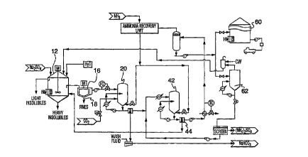
With reference to Figure 3, once the insolubles have been removed by the clarifier
and filters, and the brine 40 is ~ uu~~ at~ d to its highest salt saturation level, the solution
or brine 40 is ~ dlulakd in tank 42 with ammonia and carbon dioxide and then is passed,
for example, pumped by pump 41, into at least a first main reactor 44 or multiple reactors
where the fDrmation of the sodium b;~albOIIaL~; occurs. The t~,lUU.,IdLUl~ within the reactor
44 may vary depending on the reactor c, r;~;. ,. , ;~ .. , The final I . . .l ,a ~ of the solution
will be ,ulu~lu~ reduced to about 21~C with the brine feed ~ n ci to the reactor
44 being nn~int~inPCl above 32~C. The final ~ c; of the solution maximizes the
b;~lJulldlt; yield and prevents ~ with Na~SO4. Pressure in reactor 44 will
preferably be ~n~int~in~l at d~),u~u~iludl.l~ 350kPa(g) to a,ulJlw~illldL~,ly 1750 kPa(g).
Although not essential, this ensures the ammonia remains dissolved in solution. A
crystallizer 46 may be included du.ll~llualll to effect cryst~l' of the sodium
b;~ albullalc;. Once the crystals have formed, they may be removed from the reactor 44
and/or crystallrzer 46 through a filter means 48 which may comprise a pressure or non-
pressure-type filter. Once the crystals are removed, they may be passed to a further
filtration medium (not shown), an example of which may be a filtration screen or rotary
centrifuge device (not shown), at which point the formed crystals may be washed with
saturated sodium b;~dllJulldl~ brine or methanol as indicated at 50 and dried wlth dryer 54
or calcined to form sodium carbonate. A high yield is achievable. The wash may be then
returned via line 52 to the mixing container 14. The formed l,i~ dlbullal~ crystals, denoted
by 56, may be then removed from the system for further uses.
The filtrate or brine 58 from the first reactor 44 is reheated to ~,ulu~ulldl~ly 80~C
to 95~C in a gas recovery boiler 60, where reactivated ammonia and carbon dioxide gases
are released from the brine. The gases are routed to a gas recovery contactor 62 where
they are subjected to the raw sodium sulfate feed brine and absorbed mto solution to
,ulu~aluldl~ the feed 41 to the b;~allJullal~ reactor 44. This process reduces the chemical
The filtrate solution, denoted by numeral 64, in Figure 4 is subjected to a first
~a,uuldliull step at a t .,~ ml~ of, for example, greater than 59~C in evaporator 66 to
condition the brine by reducing the level of unreacted and residual sodium ion in the
solution. As the saturation level of the brine is obtained, sodium sulfate crystallizes from
CA 0220~199 1998-04-27
the solution before the saturation level of ammonium sulfate or double salt is achieved. The
sodium sulfate crystals are filtered at filter 68 from the first evaporation brine and washed
and dried as sodium sulfate product of high purity or recycled as indicated by 70 as feed
stock.
The filtrate 70 from the first evaporation for brine conditioning is then cooled to
approximately 20~C where crystallization of sodium sulfate and ammonium sulfate occurs
intheformofahydrateddoublesalt(Na2SO4-(NH4)2SO4-4H20)ordoublesalt/puresaltmix
in crystallizer 72. The double salt crystals are filtered by filter 74 from the cooled brine and
redissolved into the first evaporator feed brine 64 via line 76. At this point the brine 77
obtained after filtering offthe double salt, contains significantly reduced levels of sodium
to effect concentration and/or crystallization of substantially pure ammonium sulfate as a
solid or liquid form. This product may be then removed from the system via line 88 as a
liquid and stored in vessel 90 or transferred to a fertilizer evaporator 78 or crystallizer 80 to
be transferred to the solid crystal form.
If a solid crystal form is desired, then the near saturated ammonia sulfate brine is
exposed to a final evaporation step with step in crystallizer 80 to precipitate out the
ammonium sulfate in a substantial crystal size and purity of greater than 73 wt%, allowing
it to be immediately used as agricultural fertilizer. The crystals are filtered with filter 8.2.
The saturated filtrate solution from the second evaporation step is recycled via line 84 to mix
with the feed brine 77 to the double salt cooler/crystallizer to further enhance the
concentration process. The filtered crystals may then be dried with dryer 86.
Advantageously, a liquid fertilizer stored in vessel 90, which may be heated, affords
the user the opportunity of blending the liquid product with other fertilizer components and
further permits crystallization of the product as a mixed desired form. The liquid in vessel
90 may optionally be subjected to further evaporation and concentration to create a
supersaturated fertilizer solution.
Although the process as discussed herein has been indicated to be primarily
conducted in water, it will be understood by those skilled in the art that any suitable solvent
can be used provided the choice of solvent does not vary the solubility relationship necessary
CA 0220~199 1997-0~-13
WO 97/00829 PCTICA96/00420
12
to effect the process. As alternatives, glycol or glycol/water mrxtures may be employed as
the solvent.
With further reference to Figures 3 and 4, the overall process may include an
additional washing step for washing the sodium bi~ bullaL~ and ~ ,-- sulfate
~lC~ J;.dt~D separately. In one possible cul~i~,uldlio-l, the sodium b;~ JUIIaL~; which is
formed in the reactor, may be passed mto contact with a washing material, an example of
which may be a source of methanol. The resulting filtrate may then be returned to a
separation container. Simllarly, the ~ - - -- ~ sulfate crystals, may be passed through a
second independent source of methanol with the filtrate berng returned to a separation
container. The ~ -- sulfate crystals and l,;~dll,ullaL~ can be used for further uses.
Figure 5 shows a variation on the process where the b;1dl1Julldlc~ recovery systems
as set forth herein previously can be combined to be useful in a sulfur recovery plant.
Generally speaking, the area designated by numeral 100 in Figure 5 illustrates uul~v~llLiullal
apparatus employed for sulfur recovery from an acid gas stream by employing the modrfied
Claus process, consisting of a single or multiple variation of thermal and catalytic recovery
steps. Generally, the Claus process includes a feed of acid gas, globally denoted by numeral
102, which is passed into a container numeral 104, for rernoval of sour water. The stream
is then passed into a reaction furnace and waste heat exchanger, denoted by numeral 106,
where the thermal conversion occurs. The stream is then passed into a first catalytic stage
conversion system, numeral 108, and D~ln ~ ly into a further conversion, denoted by
numeral 110 which may comprise "n" stages. Liquid sulfur is removed from the stages at
112. The stream is reheated and passed into a mixing unit 114 and then further into a
collection device 116, which may comprise an cle~llu-ldlic ull~ ;LdLul or baghouse. The
solids from the collection device 116 are passed into a silo 118 and s-~b~ Iy into a feed
ulu~JdldLiull on it specifically set forth as Figure 2 at tank 16. From the feed UI- IJdldLiull
tank 16, the feed is processed in a~ ~ul-ldll~ c with the l,;~all,ulldLc; recovery system, globally
denoted by numeral 122 and specifically set forth in the fl~c~-rjrtinn for Figure 3. The
produce may then be transferred into a fertilizer recovery unit 124, the details of which have
been set forth in the .~ il,.. for Figure 4. The resultrng product is commercial grade
fertilizer. As an option, the sodium b;~,dllJUlldLC; feed from the ~ dlbull~lL~ recovery unit
CA 0220~199 1997-0~-13
Wo 97/00829 PCT/CA96/004Z0
13
122 may be passed imto a dry sorbent mjection unit 126 and the bi~lbull~-Lc then c~ ludu~ ed into the system via line 128.
It is well known to those skilled m the art that the Claus process is useful for.i~ .1',-.; .li--.,. Generally spealiing, the process is effected in two steps, namely:
N2S + 2 ~2 ~ N20 f 5~2 ~ -
2N25 + 5~2 s7 2H2~ + xSX
This generally results in an elemental sulfu} recovery of UjUjlllUAilUdU Iy 90% to 96%
m a liquid sulfur state. The remaining sulfrr containing ~ n' ~.1 is recovered in sulfur
recovery Ic~ Lliiuues such as tail gas cleanup units. By employing the recovery process as
set forth herein previously, sodium biudllJul~ c can be mtroduced into the oxidized tail gas
stream containing residual sulfur ~''-' I~''-'''-l~ and results can therefore be the production
of .. -.-.. :-.. -. su'ifate as indicated in Figure 5. By combining the modified Claus process
with the processes as set forth herein, the result is the overall sulfur removal of the order
of at least 95% or greater.
Turning to Figure 6, shown is a variation on the process in Figure 5, but for a lower
volume ~ludu~iul- sulfur plant, typically having ~JIudiu~liull levels of less than 10 tonnes per
day ~MTD) where economic constraints preclude the recovery of elemental sulfur as shown
in Figure 5. ~ ~
The acid gas stream may be as an alternative directly treated with liquid sodium
l,;~.dll,ulldl~:: or carbonate solution for r,'. ~ r,~ l and form an alterriate sulfur product~
In Figures 7 and 8, shown are variations on the overall processes according to the
present invention.
With more specific reference to Figure 7, there is illustrated an effective scheme
whereby the recovery process as set forth herein, can be employed to regenerate diy sodium
sulfate captured from a particulate collection device 150 such as an ele~llu~LdLic ~.le~iju;LdLul
or baghouse and produce sodium bicarbonate to be injected into the flue gas stream to
CA 0220~l99 1997-0~-l3
WO 97/008Z9 PCT/CA96/00420
14
primarily reduce sulfur ~ from sulfur sources such as an industrial boiler 180 and
released by means of a stack 152. The practice of injecting a dry chemical into the hot flue
gases is commonly referred to as DSI. By adapting the recovery process, discussed with
respect to Figure 3, to the DSI technique, the overall scheme becomes a continuous
dble process with no waste streams or landfill .~ ~lui., no dlJ~J.U~ ;ablc losses,
amd all by-products are ;... ...li t. 1~ U idlly useable. Using d}y sodium 1,;. -- b- - - ar.
as the reagent offers the additional advantages of further recovery of other lln~lpcir~lhl~
c" 'l" - ~ such as NO,~, HCI and SO3 from the flue gases, and improve the p r.... -. ~
of the IIU .. .I~L~ L dUII collection device 150 (i.e. ESP or baghouse). The dry sorbent technique
im addition, will not a~ ;abl~ affect the t~ -r ~ of the flue gases, thereby~-- .i ~i--i-,~ or improving the efffluent emission dispersion from the stack 152.
The sodium sulfate containing flyash compound is fransferred from the collectiondevice 116 and stored in a silo 118 (Figure 6) and blended into the feed l,lu~!dlaliull tank 16
of the process denoted by 120 (Figure 6). The feed is processed in the bil dlbulldlc recovery
system 122 and the sodium b; .dlbUII I~C; is passed into a dry sorbent injection unit 126 and
fill~udu~cd into the system via line 128. By-product from the b;~ dlbulldL~ recovery unit
122 is transferred to the fertilizer recovery unit 124, the resulting product is commercial
grade fertilizer.
Figure 8 illustrates a scheme by which the process can be modified to produce a
specific sodium carbonate or l,;~ all,ullalc mixed or pure solution which can be adapted for
use in a wet scrubber. Flue gas from the industrial boiler or tail gas unit, globally denoted
by numeral 180, is passed onto an cle. Ilu~idLic l~lt~;~J;LdlUI or baghouse 182 or other
recovery device to remove flyash at 184. A water wash contaimer 186 is provided to
circulate wash water in a single or multi level upper section of a wet scrubber 188 and
~l cnrn~ t~d levels of ~ dLtS and fluids are drawn off and passed to the lower section
of the wet scrubber 188. Separate vessels may also be employed to effect the desired result.
Once sodium sulfate at the desired ~ullc~ ldlioll level is collected from the bottom of the
wet scrubber 188 as a product of the scrubbing procedure, it is then further transferred to
feed ~ UdliUII tank 190 for thickening and ~ ~ r~ .,.. to a saturated state for feeding
into reactor 20 (not shown) from the bi_dllJUlldit recovery unit, globally referenced as 122
and shown as Figure 3. From the reactor in the bi~dllJulldL~ recovery unit 122, sodium
Wo 97100829 pcr~cAs6/oo42o
I5
bil,~lllJUlld~C is filtered from the solution and washed in either open screen, pressure type
or ~ t ~ " of these (generally shown at 48 in Figure 3). The L,;~ dll,u.,alc precipitate
is washed and reduced to less than 10% liquid aDd then fed as a slurry into a bi~l,ul.alc
slurry container 96 at a~ v/~iLu.ltcly 700 kPa(g). At this point, the bi dlhulldlc slurry in
container 96 is mixed with clean water supplied to container 96 from a feed water supply
container 98. The feed water is ~,.,,i"l~ d at a ~ o c of dlU,UlU.'iLUldlCIy 48~C. The
slurry is continually mixed and ranges m a .. ~ .., I . ,. l i.... from about 20 wt% to about 40
wt%. The slurry is then lldn~rc,-cd to a high pressure solution container 200 at a pressure
of a,u~llu~inldL~I~ 1050 IcPa(g), where a saturated solution is formed. A saturated
bildllJblldlc solution is created using additional feed water from container 98 which is
heated to dl~,ulu~ dlcly 176~C by an injection water heater 102. The final saturated
. . " . . ., a " 1 ~ solution is then injected into wet scrubber 188 by means of Ime 201 for sulfur
dioxide removal.
The ~ m ,, l ~ ~ c, pressure and ~ a i l ;~, . of reagent in the final injection solution
can be varied to control the level of SO2 removed, the desired pH of the system solutions
and the final flue gas t~ Lu~-clalu.c exiting the wet scrubbing process. As a further example,
the pressure of the injection system can be reduced to near At- ~',' ' conditions
prevalent in the wet scrubber 188. The t~ LU~. laLUle can then be reduced to near 49~C to
eliminate water heater 102 and the high pressure reactor 200. This will result in a cooler
final flue gas lululJcldlulc resulting from the cvd~ulàlivc cooling effect which may or may
not be ~ trimPnt~l to any specific a~J,ulicdLiull.
It wlll be aAu,ulc1i~-kd that the wet scrubber 188 can take any form of contacting the
reactant solution with the sulfur containing flue gas, for example, spray dryers, etc.
Further, the sodium carbonate or other suitable sodium compounds can be used as
a n pl~remrnt or cotnbined in various ratios with sodium bi~all?ulld~c to effect or enhance
the wet and dry scrubbing t- rhni,lu~c The conversion can easily be ~rcnmrlich~cl by
calcining the b;~dlbulldLc in a dry form or by increasing the t~,lll,U~ l~LulC in a liquid form
to alter the biCdlbUll~llC to carbonate form. The carbon dioxide used in the process can be
recovered in a recovery process as set forth herein.
CA 02205199 1997-05-13
WO 97100829 PCT/CA961004Z0
16
Turning -to Figure 9, showing ~ is a further ~ bc ~ according to the
present invention. The ~ hu ~ shown, a lime mixing container 70 is provided for
retaining lime in any form, e.g. a slurry or powder form to be iuLIudu~ cd into reactor 202
via line 71. By providing this addition to the recovery unit, ~;UUIlll~l~ ;dl or landfill gypsum
can be produced along with sodium 1,;~ aflJullalG as illustrated in the flow chart in Figure 9.
As a further feature, the .. ,.. ,,,.. ~ shown may imclude ammonia recovery unit 204 which
will include the usual gaseous recovery means well known to those skilled m the art. This
is useful since the ammonia is hberated . ' I to ~Ic~ ;laliull of gypsum and therefore
can be easily recovered and recycled mto the process for sodium b;~,cul7ulla~ production.
As a ~;UII;!IC4U~,lIU~, of reactor, evd~JUldlUI and crystallizer vessel size, ~ a~
~a~lir;~ .~i.,., may exist within the reactors and ~Vdl!uldlUI7 as set forth herein or the
crystallizing vessels used to enhance the crystal growth, stability and yield. In order to avoid
mriPcir~hlf- effects caused by hydrate or solvate ~ J;Idl;ull in large vessels, the process
can be performed in multiple vessels to ~ iu~ ulll.~,lll these ~liffirlllfiPc
Referring now to Figure 10, shown is one possible process route according to thepresent invention. A source of sodium sulfate, such as flyash, for example, from commercial
steam boilers containing various levels of sodium sulfate may be collected from hot flue gas
streams and llal~rc~llcd into a collection silo, globally denoted by numeral 10 in the
drawings. From the silo, the flyash may be lldll:!.l~.ll~l;l at a controlled rate into an
nll~ .ic mixing container 12, which container is mslinr~inP.(l at a I~lllU~ildLUIC; from
between about 32~C and 42~C. The light and heavy msolubles are removed in a slurry form
from the mixing container 12 at 14. The brine or filtrate is then transferred to a clarifier
16 and further filtered if necessary to polish the solution free of fine insolubles. Fine
insolubles are removed from the clarifier at 18.
Once the insûlubles have been removed by the clarifier 16, the solution or brinewhich contains a small p~ of ammonia is passed into a first main reactor 20 where
the formation of the sodium l~;uall~ul-aL~ occurs. The final ~ ,u~ laLulc; of the solution will
be I.. u~ ly reduced to about 21~C with the brine feed ~ .,lalulci to the reactor being
..".i l~; rd above 32~C. Pressure in reactor 20 will preferably be m:lint~inPd at
d~l~lu~ullldLc~]y O kPa to almost 17'iO kPa to ensure the ammonia remains m solution to
CA 0220~199 1998-04-27
' 17
effect the reaction. A crystallizer may be included downstream to effect crystallization of
the sodium bicarbonate. Once the crystals have formed, they may be processed as set forth
with respect to Figure 3 via filtration screen 24. The wash may be then returned via line 26
to the mixing container 12. The formed bicarbonate crystals may be then removed from the
system via line 28 for further uses.
The filtrate or brine from the first reactor is reheated back to approximately 32~C.
The solution is maintained at a temperature of at least 32 ~ C and then passed into reactor 32.
Once in reactor 32, the brine solution is subjected with excess ammonium at a concentration
of approximately 20 weight percent.
The pressure in the reactor is carefully controlledby varying the injection of ammonia
(approximately 450 kPa) thereby controlling the desired concentration of excess ammonium.
In reactor 32, the injection of the solution with ammonia shifts the equilibrium solubility of
the solution of the reaction, denoted hereinabove, to favour the formation of ammonium
sulfate precipitate. The temperature in the reactor is maint~ined at 32~C to keep free sodium
cations soluble and to prevent cont~rnination of the ammonium sulfate with undesirable
solvates. When desired, the ammonia concentration can be altered by changing the pressure
control. Similar to the description for reactor 20, reactor 32 may include a crystallizer
downstream to effect the formation of ammonium sulfate crystals. Once formed, the crystals
may be passed onto a pressure filter medium 34 and washed with suitable wash. The
so-formed ammonium sulfate crystals can then be removed by line 36 for further uses. The
wash may be returned to the mixing container 12 via line 38 for further uses. The
ammonium containing filtrate remaining after the precipitation of the ammonium sulfate
crystals, may be flashed off, compressed and condensed and collected in to a surge drum 40
as is known in the art. Once collected, the ammonia solution may be used for reinjection in
the system.
The final recovered solution, containing soluble levels of ammonia can be recycled
to the mixing container 12 to complete the continuous operation.
By practicing the above method, a purity of ammonium sulfate greater than 50% byweight is achievable.
CA 0220~l99 l997-0~-l3
WO 97/00829 PCTtCA96/00420
18
Adv~ ,. u~ly, the ammonia can be 5l~hct:~nti~11y recovered for reuse which has
positive economic advd~ for the entire process.
Figure 11 shows a further variation on the process accordmg to Figure 10. In Figure
11, the brine r~ step is employed between reactors 20 and 32. The brine
. ~.,..I:~il...: ." step is effective to purify the feed stream for introduction into reactor 32 for
eventual formation of nl.. l. .l sulfate by the further reduction of sodium ion
.:ullc.,l.lldLiull from the feed stream entering into reactor 32.
Once the sodium b;~ll/ulldlc reaction has been rnmrl~t~--l, the b;-,dllJUlldLC
IJI~,~,;IJ;dLC is removed as set forth herein with respect to Figure 10 and the brine is
transferred to ~ reactor 42. In reactor 42, the l U~ dliUI! of the ammonia is
increased to saturate the solution while the ~ c of the reactor is lowered to
a,ul lu~ill-fiLcly 7~C. This results in the formation of a ~71C~.;,UiLdLC rnmrricing either pure
sodium sulfate, or a mixed precipitate of sodium sulfate and ~.. sulfate. These
.1;Ldl~ are then filtered by flter 44 and the crystals eventually passed back into contact
with mixing container 12. The filtrate is fed to reactor 32 and ....i..l ~i... fl under at least the
same pressure conditions as indicated for Figure 10. Once in reactor 20, the filtrate
undergoes the reaction as mdicated hcl~;lldbuvc, the result is the formation of n~
sulfate precipitate, however, the precipitate is formed in an ~ llvilulllll.~liL where the sodium
cation ~:ul~ LIdLiull is si~lirud~lly reduced in view of the i~ process using
illl~.~l..l;.lr. reactor 42. The result of the process is a solution Cull~llLIdliull of a
----.,.- -, .- sulfate which will effect a precipitate of a ~ - f Inn I i-..l greater than 73% by
weight.
Referring now to Figure 12, shown is a further alternate dlldllt,_lU.,II~ by which the
process may be practised. In Figure 12, the overall process may include a separate washing
step for washing the sodium ~ albUlldLC and .. ~ ~ . . ~ ~- -- -i . . ~ ~ . sulfate ,UI cui,uiL..Lf .~ separately. In
one possible cul~ri~ uldLiull, the sodium hiudlbulldLc which is formed in reactor 20, may be
passed into contact with a washing material, an example of which may be a source of
methanol 50. The resulting filtrate may then be returned to mixing contamer 12 via Ime 52.
CA 0220~199 1997-0~-13
WO 97/00829 PCT~CA96/00420
19
Similarly, the ~ sulfate crystals f.ormed in reactor 42, may be passed through
a second i"~ 1 source of methanol 54 with the filtrate being returned to mixing
contamer by line 56. The, ~ suhfare crystals and b;l,dllJUlldl~ can then be used for
further uses.
Referring now to Figure 13, shown is a further variation on the schematic process
shown m Figure I0. In the process shown in Figure 13, the filtrate recovered from the
sodium b;~lJullaL~ reaction can be made to be sllh~ontiolly pure liquid product, e.g. a
fertilizer m the near saturated state. This facilitates blending the liquid product with other
fertilizer ~ r~ or permits crystqlli7Atir n of the product in the desired form. The
liquid product may be passed from reactor 20 to the brine ~ , container 42 where
the t~lulJ~ldlul~ of the solution is reduced to alJ~Jlu~illldLul~ 7DC as set forth herein
previously with respect to Figure 11. In this ~ -- 1,o,l- 1-- 1, the ammonia ( 1lll. - --II,l~ il l-- is
imcreased from about 10% to about 50% or greater by weight to therefore provide a
l..,o~;l solution. The result is the ~lc~;~J;LdLiull Of .""~".... ~s d sodium sulfate or
mixed salts of Hl~ 1 and sodium sulfate. The filtrate in this situation is 5llhctontiHlly
saturated liquid: ~ sulfate which can then be passed on to a storage unit 60. As
a further alternative, a user may simply pick up the liquid ~ 1 sulfate orAl -~, the . sulfate may be pumped into a ~u~ liul-al c~d~uldLul
(crystallizer) 62 to afford mixing the liquid with additional fertilizer ~ l " " IF I ' to have the
final product crystallized.
The brine ,--....lilir...i"g can be performed m a single step or it may be rr~nrl;tionP~l
in multiple steps to achieve increased removal of sodium cations; this inherently leads to
increased purity of the ,..-.--.. ,.-i-- .- sulfate fertilizer. The above-mentioned steps can be any
~-----1- ~"li~--, of known (salting out) steps i.e. ~val~ulaLiull, addition of excess ammonia, ion
exchange, cooling among other tel hnirluPc
Typical]y, the ~dl)ol dLiul~ is carried out at a; r ~ . H ~ ; of greater than S9DC while
other unit operations are carried out at a ~ Iess than 59DC.
Figure 14 shows a variation on the process where the bi~.dll,ullaI~ recovery systems
can be combined to be useful in a sulfur recovery plant. The area designated by numeral
CA 0220~l99 1997-0~-l3
WO 97/00829 PCT/CA96/00420
70 in Figure 14 illustrates . u~ u~ apparatus employed for sulfur recoverg from an acid
gas stream by employing the modified Claus process, consisting of a single or multiple
variation of thermal and catalytic recovery steps.
By employing the recovery process as set forth herein previously, sodium l,;~ll,ullaLt
can be il.lludu~l into the tail gas stream contaming residual sulfur ~ and results
can therefore be the l ludu~.Liul- of il~ - sulfate as indicated in Figure l4. The overall
modified Claus process, denoted by numeral 70 can be combined with the overall process
for producmg ~ ~ sulfate, the gTOUp of steps of which is generally mdicated by
numeral 115 in the figure. The broad steps as illustrated in the figure are generally
common steps to those shown in Figures 10 and 11. By combining tbe modified Claus
process with the processes as set forth herein, the result is sulfur removal of the order of
at least 95% or greater.
Figure 15 illustrates a further process variation for a lower volume 10 MTD
,IJlUdUUliUll sulfur plant. The steps for the process are similar to those for Figure 14 and the
treatment of the sulfur compoumd is generally denoted by the sequence of events as
indicated by numeral 115.
The acid gas stream may be as an alternative directly treated with liquid sodiumb;I~IIbUII~ILt: or carbonate solution for ~l~c~llfilri7~tinn and form an alternate sulfur product.
Turning to Figure l6, shown 5fh~n~tirAIIy is a further ~ ~ . ,l ~l ..1 l l A lime mixing
container 70 is provided for retaining lime in any form, e.g. a slurry, powder, etc. to be
introduced into reactor 32 via lme 72. By proviaing this addition to the l,i~l bUll~l~t process,
commercial or landfill gypsum can be produced along with sodium ~ ,cllbUII~ ; as illustrated
in Figure 16. The A l l '~ shown may include ammonia recovery unit 74 which will
include the usual gaseous recovery means well known to those skilled in the art. This is
useful since the ammonia is liberated ~ub.,equ-,..l to ,UI~ liull of gypsum and therefor
can be easily recovered.
CA 0220~199 1997-0~-13
WO 97/00829 PCT~CA96/00420
21
Turning to Figure 17, shown is a further variation on the overall processes. In Figure
17, a FGD process using a wet scrubbing system for ~ r~ ;"" employs sodium
carbonate or bi~dllJulldL~ as the active reagent.
In the c~ul,o,'i illustrated, flue gas from the nndustrial boiler o} tail gas unit,
globally denoted by numeral 90, is passed onto an clc.llu~LdLiL ,u. ~ J;LdlUI or baghouse 92
or other recovery device to remove ilyash at 93. A water wash container 94 is provided to
circulate wash water nn the upper section of the scrubber and r ~ ~.. l,a~ d levels of
e~ ;u;LdiL~ and rduids are drawn off from container 94 and passed to the lower section of
the scrubber 95. Once sodium sulfate is collected from the bottom of scrubber 95 as a
product of the scrubbing procedure, it is then further Lldll~f~,llcd to mixing container 12 for
thickening and ~ l . . il i. ~l il ,.. to a saturated state for feeding into reactor 20. From reactor
20, sodium b;- dlbul~dLc is filtered from the solution and washed in either open screen,
pressure type, vacuum type, centrifuge or cyclone type filters or any ~ a8~ of these
(generally shown at 97). The b;~dllJulldle precipitate is washed and reduced to less than
10% liquid and then fed as a slurry into a b;~ dlbullaLe slurry container 96 at a~ u~ullaLcily
7001cPa. At this point, the b;~dlbulldLG slurry in container 96 is mrxed with clean water
supplied to container 96 from a feed water supply container 98. The feed water is
mDint~inPd at a LCLU~JCldLUlCi of d~ JIU,'d~lld~ 48~C The slurry is continually mixed and
ranges in a LUnC-,IlLldLiUll of between about 20% by weight to about 40% by weight. The
slurry is then transferred to a high pressure solution container 100 at a pressure of
d,u,ulu~LuldLLI~ 1050 kPa, where a saturated solution is formed. A saturated b;Ldll)ullaLc
solution is created using additional boiler feed water from container 98 which is heated to
d~lu~hlldLc]y 176~C by an injection water heater 102. The frnal saturated LunL~l.LIdL~d
solution is then injected nnto wet scrubber 95 for sulfur dioxide removal.
The LLlll~J~,ldLUlC, pressure and LUIl~ ild[iUII of reagent in the final injection solution
can be varied to control the level of SO2 removed and the final f ue gas LClllpCldLUlC exiting
~ the wet scrubbing process. As a further example, the ~ c; and pressure can be
reduced to near ;lOI~l ~l llf ir conditions prevalent in the scrubber. The LLIII~I~,ldlUlC can be
reduced to 45DC to eliminate water heater 102 and the high pressure reactor 100. This will
result in a cooler final flue gas t~ JCildLUlC resulting from the ~d~UIdliVC cooling effect
which may or may not be detrimental to any specific d~J~J];~.diiUn.
CA 0220~199 1997-0~-13
WO 97/00829 PCT/CA96/00420
22
In addition, it will be d~ c~.;aLl,d that the wet scrubber 104 can take any form of
rnntr.~rting the reactant solution with the sulfur containing flue gas, for exarnple spray
driers, etc.
As an alternative to reducmg sodium ion content, the excess ammonia treatment may
be replaced by an ion exchange unit operation. In this operation, sodium ions can be
replaced with ~ ,. ",; ions to preclude the formation of ~ ,.1.1.' sodium ~ . " "1
imter alia.
As is known m the art, the design of ion exchange depends on three broad
, namely, resin type, resin capacity and selectivity. As an option, by employingthe ion exchange im an operation, the resin may be initially loaded through the use of a
lCE~ dliVC solution, for example, r carbonate with: ions. When a
fluid stream of .,..,..".~: ,. and sodium sulfate, ~ the resin, which is loaded with
,.... i..... , there will be a proclivity to exchange sodium. This~proclivity will also
adv:lntSlgl~o-~cly ensure that the fluid always l,llCuu..'~,15 fresh resin only loaded with
,....",.",;.....
The ion exchange scheme can be used in any number of locations in the process asset forth herein previously to enrich the stream with ammonia ions in exchange for sodium.
An example of the process using an ion exchange scheme for treatment of brine from the
reactor is shown in Figure 18. The ion exchamge scheme preferably uses several columns
in different operating modes, examples of which include exchange, ~ l i- - . - and standby.
The example shown in Figure 18 employs a reactor unit 220 in the ~ludu~ LiUII of resin
~g. . I<~li"g solution using ammonia containing condensed water from the fertilizer
cvd,uuldlul-crystallizer unit as one of the feed ~ The exit ]iquor from the resin
~g. ~ , may be recycled in the system. Figures 19 and 20 show additional examples
of the location for the ion exchange unit together with optional c~ g steps using the
..... l;li.. ".. 42 as set forth herein previously.
It will be dlU~ ,- idl~d by those skilled that Figures 18 through 20 are only exemplary
of those positions where the ion exchange system 220 could be employed.
CA 0220~199 1997-0~-13
wo 97/00829 PC r/cAs6/00420
23
Figure 21 illustrates an overall schematic view of a further option employing cooling
to effect the desirable results accordmg to the present invention. 1~~ r i". . i ;~ ~ ~ may be used
as a further ?l .~ to the techniques of ev~ dliull, ammonia shiftmg or ion exchange
to reduce sodium ion content to thereoy result in a stream having a higher Lull~c~lLIdLiull
of: sulfate. One possible scheme is to cool the E~ dall UdlU by the cross exchange
vvith a much colder stream. As an example, the feed may be cooled within a range of 03C
to -40~C. A desirable ~ ~ ~ ~ c is -I 1~C. Due to the aubrl c~ ~ ulg ranges required for the
cooling, a standard closed loop ,~r ;L" ~,~ system may be used to cool the hquid in
exchange with the feed. Propane and ammonia ICrl;~j~ldll.~, glycols and any other
acceptable ~crli~;~ldllL that remains functional in the given 1 - 11~ c range can be
employed in the system.
Figure 21 illustrates one possible i:llldl~ ,.lL where the l~r, ;c- ~ " - unit operation
is broadly denoted by numeral 222. At cold l ~ o ~ ~ . ~, the solubility of the 1,l ll l ~; ~- ~- - - 1-
present in the system is sllhctSlnf~ y reduced. Salts that can not be held by the solution
~Ic~;~iLdLe. The primary l,l~, will be hydrated sodium sulfate and lesser quantities
of ~-,...~ -- and sodium l,icdll,ullale. The exiting liquid phase 224, exiting from the
erli~;~ ldiiUll unit 222, will contain less sodium ions than the liquid phase entermg into the
lurli~ dLiul. unit operation as a result of the ~ JiLaLioll of sodium r.nmrolln~c Some
,...--"~ --sulfatemayprecipitateshouldthe-,u.-~c.lL-dLiullinthefeedsolutionbehighand
the ~eLul eldiulc low enough. Although this is the case, ~lul l-lLiul-ally more ~..--."...;-~ -
c.--..l.~....--l~ remain in the liquid phase than the sodium .--.-.I,u~ The result is a liquid
phase having much less sodium ion content to be used for the IJlullu1Liull of ~
sulfate. This is a distinct advantage by hl~ u~ illg the l - r- :, ~ ", l ;- -- l operation 222 based
on the phase l~l~li""~ , of the wlll~uullda in the system. The precipitated solids may be
separated from the liquid phase of the cold stream by means of any suitable solid separation
device (not shown). The solids can be recirculated through the system as indicated by
numeral 226.
= = ~ ~
It has been found that the I ,-f- i, . . .~ scheme can be further ~m~mPntPd by adding
excess ~ ."..".i -.- in the . ~ step with a 1:11~ range varying up to 20%
by weight and typically 10% by weight depending on the residual level of sodium desired
in the fertilizer evaporator feed brine.