Note: Descriptions are shown in the official language in which they were submitted.
'" CA 02205211 1997-OS-12
,~ ,
1
VARIABLE PIPE DIFFUSER FOR CENTRIFUGAL COMPRESSOR
The present Invention relates to centrifugal
compressors in general and in particular to a diffuser
structure for centrifugal compressor.
One of the major problems arising in the use of
centrifugal vapor compressors for applications where the
compressor load varies over a wide range is flow
stabilization through the compressor. The compressor
inlet, impeller and diffuser passages must be sized to
provide for the maximum volumetric flow rate desired.
When there is a low volumetric flow rate through such a
compressor, the flow becomes unstable. As the
volumetric flow rate is decreased from a stable range,
a range of slightly unstableflow is entered. In this
range, there appears to be a partial reversal of flow in
the diffuser passage, creating noises and lowering the
compressor efficiency. Below this range, the compressor
enters what is known as surge, wherein there are
periodic complete flow reversals in the diffuser
passage, destroying the efficiency of the machine and
endangering the integrity of the machine elements.
Since a wide range of volumetric flow rates is desirable
in many compressor applications, numerous modifications
have been suggested to improve flow stability at low
volumetric flow rates.
Many schemes have been devised to maintain high
machine efficiencies over a wide operation range. In
U.S. Pat. No. 4,070,123, the entire impeller wheel
configuration is varied in response to load changes in
an effort to match the machine performance with the
CA 02205211 1997-OS-12
2
changing load demands. Adjustable diffuser flow
restrictors are also described in U.S. Pat. No.
3,362,625 which serve to regulate the flow within the
diffuser in an effort to improve stability at low
volumetric flow rates.
A common technique for maintaining high operating
efficiency over a wide flow range in a centrifugal
machine is through use of the variable width diffuser in
conjunction with fixed diffuser guide vanes.
U.S. Pat. Nos. 2,996,996 and 4,378,194, issued to
a common assignee, describe variable width vaned
diffusers wherein the diffuser vanes are securely
affixed, as by bolting to one of the diffuser walls.
The vanes are adapted to pass through openings formed in
the other wall thus permitting the geometry of the
diffuser to be changed in response to changing load
conditions.
Fixedly mounting the diffuser blades to one of
the diffuser walls presents a number of problems
particularly in regard to the manufacture, maintenance
and operation of the machine. Little space is afforded
for securing the vanes in the assembly. Any
misalignment of the vanes will cause the vane to bind or
rub against the opposite wall as it is repositioned.
Similarly, if one or more vanes in the series has to be
replaced in the assembly, the entire machine generally
has to be taken apart in order to effect the
replacement.
According to its major aspects and broadly
stated, the present invention relates to a variable
geometry pipe diffuser for a centrifugal compressor.
'~ CA 02205211 1997-OS-12
3
A variable geometry pipe diffuser (which may also
be termed a split-ring pipe diffuser) according to the
present invention includes a first, inner ring and a
second outer ring. The inner and outer rings have
complementary inlet flow channel sections formed
therein. That is, each inlet flow channel section of
the inner ring has a complementary inlet flow channel
section formed in the outer ring. The inner ring and
outer ring are rotatable respective one another.
Preferably, the inner ring rotates circumferentially
within the outer ring. However the outer ring can
instead be made rotatable circumferentially about a
stationary inner ring.
When one ring is rotated respective the other,
the alignment between each pair of complementary air
channel sections of the rings change. The rings are
adjustable between a first, open position wherein
complementary channel sections of the rings are aligned
to allow a maximum amount of fluid to pass through the
inner and outer rings, and a second, closed position
wherein fluid flow through the channels is restricted
and decreased volume of fluid passes through
complementary inlet flow channel sections of the inner
and outer rings. The rings may also be made adjustable
to any number of intermediate positions between the open
and closed positions.
In the second, closed position, at least about
10% the volume of flow as in the fully open position
should flow through the diffuser so as to prevent
excessive thermodynamic heating of component parts of
the machine. To the end that thermodynamic heating is
'~ CA 02205211 1997-OS-12
4
prevented, the amount of relative rotation between the
two ring sections should be limited to an amount of
rotation necessary to effect a second, closed position.
In other words, the rings should not be adjustable to
completely close off a flow of fluid therebetween. The
degree of allowable rotation between the two rings is
determined by the desired flow between the rings in a
fully closed position, and the number and volume of
inlet air channels in the ring sections. Complete
closure of an inlet flow channel can also be prevented
by providing an inner ring having non-channel portions
thereof sized to a width less than the minimum width of
an outer ring flow channel.
By adjusting the variable pipe diffuser toward a
closed position, the surge point in a performance plot
for a compressor having the present diffuser is adjusted
toward a lower flow rate. The pressure generated by a
compressor at this lower flow rate is approximately the
same as that of a compressor having a diffuser in the
fully open position. Accordingly, the present invention
is especially useful for adjusting compressor
characteristics so that a compressor can meet a low flow
rate, high pressure ratio condition. Such an operating
condition is required, for example, where there is a
large difference between indoor and outdoor ambient
temperature, but low system loading.
The efficiency of a compressor at a given
operating condition can often by optimized by combining
an adjustment of a variable diffuser as described herein
with an adjustment of a compressor's inlet guide vanes.
CA 02205211 1997-OS-12
In the drawings, wherein like numerals are used
to indicate the same elements throughout the views,
Fig. 1 is a cross-sectional side view of
compressor according to the invention having a variable
pipe diffuser;
Fig. 2 is a perspective view of a variable pipe
diffuser according to the invention;
Figs. 3 and 4 are cross-sectional front views of
a variable pipe diffuser in accordance with the
invention in a first, open, and a second, closed
position, respectively;
Fig. 5 is a performance diagram for a variable
pipe diffuser according to-the invention;
Fig. 6 is a performance diagram for a compressor
having inlet guide vanes only;
Fig. 7 is a performance diagram for a compressor
according to the invention having a variable pipe
diffuser and inlet guide vanes.
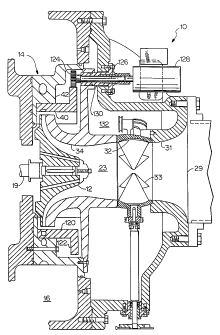
Referring now to Fig. 1, the invention is shown
as installed in a centrigual compressor 10 having an
impeller 12 for accelerating refrigerant vapor to a high
velocity, a diffuser 14 for decelerating the refrigerant
to a low velocity while converting kinetic energy to
pressure energy, and a discharge plenum in the form of a
collector 16 to collect the discharge vapor for
subsequent flow to a condenser. Power to the impeller
12 is provided by an electric motor (not shown) which is
hermetically sealed in the other end of the compressor
and which operates to rotate a high speed shaft 19.
Referring now to the manner in which the
refrigerant flow occurs in the compressor 10, the
' CA 02205211 1997-OS-12
6
refrigerant enters the inlet opening 29 of the suction
housing 31, passes through the blade ring assembly 32
and the guide vanes 33, and then enters the compression
suction area 23 which leads to the compression area
defined on its inner side by the impeller 12 and on its
outer side by the shroud 34. After compression, the
refrigerant then flows into the diffuser 14, the
collector 16 and the discharge line (not shown).
As seen in Figs. 1-3, a variable geometry pipe
diffuser 14 according to the present invention includes
a first, inner ring 40 and a second outer ring 42. The
ir~ner and outer rings have complementary flow channel
sections 44 and 46 formed therein. That is, each flow
channel section 44 of the inner ring 40 has a
complementary channel section 46 formed in outer ring
42. Inner ring 40 and outer ring 42 are rotatable
respective one another. Preferably, inner ring 40
rotates circumferentially within outer ring 42.
However, outer ring 42 can instead be made rotatable
circumferentially about a stationary inner ring 40.
When one ring is rotated respective the other,
the alignment between each pair of complementary inlet
flow channels of the inner and outer rings changes as
seen with reference to Figs. 3 and 4. Rings 40 and 42
are adjustable between a first open position, as
illustrated in Fig. 3, wherein complementary channel
sections are aligned and a maximum amount of fluid
passes through inner and outer rings 40 and 42, and a
second, closed position, as illustrated in Fig. 4,
wherein complementary channels are misaligned and flow
through the channel sections 44 adn 46 is restricted.
CA 02205211 1997-OS-12
7
The flow of fluid through diffuser 14 in a second
closed position in relation to the open position flow
rate is determined by the ratio of the minimum cross-
sectional area of a flow channel of a diffuser in a
closed position to the minimum cross-sectional area of a
flow channel (defined by complementary channel sections
44 and 46) in an open position. This minimum flow
channel area, known as the "throat area" will generally
be determined by the smallest diameter of the flow
passage 52 of the inner ring channel 44 when diffuser 14
is in an open position, and will be controlled by the
width 53 at the interface between the inner and outer
rings 40 and 42 when diffuser 14 is in a second closed
position. For example, if a diffuser channel has a
minimum area (throat area) of 1/8 in. in a second closed
position, and a minimum area (throat area) of 1/4 in. in
an open position then the volumetric flow rate of fluid
through a diffuser in a closed position will be about
50% of the flow rate as in a fully open position. The
flow rate of fluid through compressor 10 when diffuser
14 is in a second, closed position, will generally be
between about 10% and 100% of the flow rate of fluid
through compressor 10 when diffuser is in a first open
position.
In a second closed position (Fig. 4), at least
about 10% the volume of flow as in the fully open
position should flow through diffuser 14 so as to
prevent excessive thermodynamic heating of component
parts of compressor 10. To the end that a condition of
excessive thermodynamic heating is avoided, the amount
of relative rotation betweenthe two ring sections
CA 02205211 1997-OS-12
. , .
8
should be limited to an amount of rotation necessary to
effect a second closed position. In other words, the
rings should not be adjustable to completely close off a
flow of fluid therebetween. The degree of allowable
rotation betweer_ the two rings is determined by the
desired flow between the rings in a fully closed
position, and the number and volume of inlet flow
channel sections 44, 46 in the ring sections 40 and 42
in relation to the volume of the ring sections 40 and
42. Complete closure of an inlet flow channel can also
be prevented at providing an inner ring 40 having non-
channel portions thereof sized to a width less than the
minimum width of an outer ring channel section 46.
Continuing with reference to Fig. 4, R2 defines
the radius of the impeller tip, R3 defines the radius of
inner ring 40, and R4 defines the radius of outer ring.
By making the thickness, defined by the Quantity T = R3-
R2 of inner ring 40 no larger than is necessary to block
a desired portion (e. g. 50s of flow) of flow through
outer ring channels 46, the flow of fluid through
diffuser 14 can be efficiently controlled. Rotation of
the inner ring with respect to the outer ring will
reduce the diffuser throat area before any diffusion has
taken place, thus preventing flow acceleration after
diffusion. Also, the smaller the inner ring thickness,
T, the smaller the turning angles of the flow through
the partially closed-off variable pipe diffuser. Both
of the above-described effects tend to improve
compressor efficiency under part-load operating
conditions.
CA 02205211 2001-06-29
9
A variable pipe diffuser in accordance with the
invention can alsc be made by providing an inner ring 40
that is moveable axially in relation to an outer ring
42. Such an embodiment is normally not as preferred as
the pair of circumfF~rentially rotatable rings described
because, in a pair of diffuser rings moveable axially in
relation to one another, there are high turning losses
resulting from the 90° turns involved. The rings axially
in relation to one another can be provided similar to
those described in commonly assigned U.S. Pat. Nos.
4,527,949; 4,378,194; and 4,219,305
Operation and use of the present invention can be
understood with reference to Fig. 5 showing a
performance diagram for a compressor having a variable
pipe diffuser according to the invention integrated .
therein. The performance diagram of Fig. 5, includes a
plurality of performance plots, each corresponding to a
discreet positioning between inner and outer ring
sections 40 and 42. Each performance plot, e.g. 60, is
characterized by a spurge point, e.g. 70, which is the
point of maximum available pressure. Operating a
compressor at a flow rate at or below the surge point
will likely result i.n a surge condition, as discussed in
the Background of the Invention section herein.
For purposes of illustrating the invention, plot
60 may correspond, f:or example, to a first, open
position, plot 62 may correspond to an intermediate 2
degree closed position, plot 64 may correspond to an
intermediate 4 degree closed position, and plot 68 may
correspond to a maximum 8 degree closed position.
CA 02205211 1997-OS-12
It is seen that adjusting ring sections 40 and 42
toward a closed position has the effect of adjusting the
surge point e.g. 70, 72 in a performance plot for a
compressor toward a lower flow rate. Thus, a surge
condition can be avoided during periods of low flow
demand by adjusting diffuser rings 40 and 42 toward a
closed position.
It is helpful to understanding the invention to
compare performance diagram of Fig. 5, for a compressor
having a variable diffuser to the performance diagram 7
shown in Fig. 6 corresponding to a compressor having
adjustable inlet guide vanes only. In Fig. 6, plots 80,
82, 84, and 86 and 88 correspond to discreet positioning
of guide vanes 33 in increasingly closed positions. It
is seen that closing guide vanes 33, like the closing of
diffuser ring sections 40 and 42 has the effect of
lowering the surge point flow rate. Thus, a surge
condition can often be avoided by adjusting inlet guide
vanes 33 toward a closed position.
However, it is seen from the performance diagram
of Fig. 6 that adjusting guide vanes 33 toward a closed
position has the further effect of lowering the head
pressure available from compressor 10 at the surge
point. Hence, a low flow rate operating condition
requiring a relatively high pressure cannot be satisfied
by adjusting guide vanes 33 alone.
By contrast, it is seen from the performance
diagram of Fig. 5 that surge point pressure available
from compressor 10 remains essentially stable when
diffuser rings 40 and 42 are adjusted toward a closed
position. Hence an operating condition requiring a low
CA 02205211 1997-OS-12
11
flow rate and high compressor pressure can be satisfied
by adjusting diffuser rings 40 and 42 toward a closed
position.
An operating condition requiring a low flow rate
and a high pressure ratio relative to the full load
operating pressure ratio (e.g. 90% of full load) is
common in the case where there is a large difference
(e.g. about 50° F or more) between the ambient air
temperature and indoor temperature, but occasional light
loading in a building being cooled. In such a
situation, a relatively high compressor pressure ratio
(e. g. above about 2.5) is required by the refrigerant
saturation pressures corresponding to the condenser, and
evaporation temperatures, but only a reduced flow rate
e.g. 25% of full load is needed to remove the heat
generated within the building. Fig. 7 shows a
performance diagram for a compressor having both
adjustable guide vanes and a variable pipe diffuser in
accordance with the invention. It is seen that
efficiency of a compressor can often be optimized by
combining an adjustment of guide vanes 33 with an
adjustment of diffuser rings 40 and 42. With reference
to Fig. 7 dash curves 111, 112, 113, 114, 115, and 116
show performance plots for a compressor having a
variable diffuser in a full open position for various
positioning of inlet guide vanes 33, while solid curves
101, 102, 103, 104 and 105 show performance plots for a
compressor having closed (here, there is about 40% of
original flow rate in the closed position) diffuser
rings at various guide vane positioning. As is well
known to those skilled in the art, a compressor operates
CA 02205211 1997-OS-12
a
12
at optimum efficiency when operating at the "knee" (e. g.
81 at Fig. 6j of the performance plot characterizing
performance-of the compressor. With reference to
diagram 7, the operating condition requiring, for
example, a pressure of about 0.7 maximum, and a flow
rate of about 0.3 maximum would be most efficiently
satisfied by a compressor operating in accordance with
plot 104, realized by adjusting diffuser rings 40 and 42
to a closed position and by adjusting guide vanes 33 to
a 10 degree position.
A simple mechanical apparatus for rotating inner
ring 40 circumferentially within outer ring 42 is
described with reference again to Fig. 1. Cylinder 120,
integral with inner ring 40, extends coextensively from
inner ring 40 and has fixedly attached thereto flange
122 which extends radially outwardly from cylinder 120.
In gearing relation with flange 122 is gear 124 which is
driven via axle 126 by motor 128. Motor 128 is selected
and controlled to effect movement of inner ring 40 in
relation to outer ring 42 between fully open and a
second closed position and any number of intermediate
positions therebetween. Axle 126 is housed in a
conventional containment housing 130 which hermetically
seals axle 126 from compressor interior 132 and which
prevents leakage of fluid out of compressor 10 through
containment housing 130.
As best seen in Fig. 2, outer ring 42 may have
seat 136 for assuring alignment between inner ring 40
and outer ring 42, and for preventing leakage of fluid
through the interface between the two rings.