Note: Descriptions are shown in the official language in which they were submitted.
CA 0220~268 1997-0~-13
WO96/lS439 PCT~S95/15439
DISPOSABLE ELECTRONIC DIAGNOSTIC INSTRUMENT
BACKGROUND OF THE INVENTION
.
l. Field of the Invention
The present invention relates geneally to a disposable
electronic diagnostic instrument, and more particularly
pertains to a disposable electronic diagnostic instrument
designed for use in an Over-the-Counter (OTC) cholesterol
test kit for measuring cholesterol levels of blood. The
diagnostic instrument is designed and calibrated
specifically for use with diagnostic test strips supplied
with the OTC cholesterol test kit for measuring and
displaying the cholesterol level of a tested whole blood
sample.
In greater detail, the subject invention relates to a
disposable electronic diagnostic instrument supplied as
part of an Over-the-Counter (OTC) cholesterol test kit for
measuring blood cholesterol levels. The OTC cholesterol
test kit consists of the disposable electronic diagnostic
instrument, chemistry test strips to which a whole blood
sample is applied, and an instructional leaflet. The OTC
cholesterol test kit can optionally include lancet devices,
antiseptic alcohol swabs, and adhesive bandages. The OTC
cholesterol test kit facilitates accurate measurements of
blood cholesterol levels.
One major long term health concern today is the level of
cholesterol in a person's blood. It is well known that
SUBSTITUTE SHEET (RULE 26)
CA 0220~268 1997-0~-13
WO 96tl5439 PCT/~JS95/15439
persons having high levels of blood cholesterol are more
susceptible to various heart and circulatory ailments than
those having lower blood cholesterol levels. Because blood
cholesterol can be managed by a person through diet or
medication, it is important for a person concerned about
cholesterol level to be able to easily, frequently and
accurately measure the concentration of cholesterol in
blood in order to be able to take appropriate corrective
actions to control blood cholesterol level. Blood
cholesterol level is one example of a bodily constituent
which is capable of being controlled by individual actions
through diet, exercise and the like. It would be highly
desirable if an individual could make easy, frequent and
accurate measurements of blood cholesterol level.
2. Discussion of the Prior Art
Instruments capable of electronically detecting the
colorimetric response of a test strip are commercially
available, such as OneTouch II~ available from Lifescan
Inc., the Tracer~ II, Accu-Chek~ II~, Accu-Chek~ Easy~,
Accu-Chek~ II Freedom~, and the Reflotron~ from Boehringer
Mannheim Corporation, Clinitek~ 1100 System and
Glucometer~, available from Ames Division of Miles
Laboratories, Rapidimat~ II/T available from Behring
Diagnostics Inc., Companion~ 2 available from MediSense,
Inc., and the Answer~ product available from Wampole
Laboratories. Other suitable instruments are similar to
those described in U.S. Patent 4,935,346.
SU13STITUTE SHEET(RUI E 26)
CA 0220~268 1997-0~-13
WO96115439 PCT~S95/15439
SUMMARY OF THE INVENTION
The present invention provides:
A disposable diagnostic instrument calibrated for use
with a test strip to which blood is applied,
comprising:
a. an instrument housing having keying guides
defining a location at which said strip is placed,
and defining a test reading aperture on said strip
on which one or more drops of blood to be tested
are inoculated, said test reading aperture
defining a test area;
b. a light source positioned to emit radiation of
desired wavelengths towards said test area and a
photodetector positioned to detect radiation
reflected bly said test area;
c. a display mounted on said instrument housing for
displaying instrmental prompt icons and
cholesterol level readings;
d. a first control circuit, said first control
circuit performing self-diagnostic testing of said
instrument;
e. a second control circuit, said second control
circuit controlling the operation of said light
source, analyzing the output signal of said
SUBSTITUTE SHEET ~RULE ~6)
CA 0220~268 l997-0~-l3
WO 96/15439 PCT/US95/15439
photodetector, and controlling the operation of
said display.
The disposable electronic diagnostic instrument of the
present invention is calibrated to a specific test strip
lot and has keying guides defining a location at which a
test strip is placed thereby conferring to an Over-the-
Counter consumer an accurate easy instrument for operation.
Accordingly, the present invention provides a disposable
electronic diagnostic instrument designed for use in an
Over-the-Counter (OTC) cholesterol test kit for measuring
cholesterol levels of blood. The diagnostic instrument is
designed and calibrated specifically for use with
diagnostic test strips supplied with the OTC cholesterol
test kit, for measuring and displaying the cholesterol
level of a tested whole blood sample. The OTC cholesterol
test kit consists of the disposable electronic diagnostic
instrument, chemistry test strips to which a whole ~lood
sample is applied, and an instructional leaflet. The OTC
cholesterol test kit can optionally include lancet devices,
antiseptic alcohol swabs, and adhesive bandages. The OTC
cholesterol test kit facilitates accurate measurements of
blood cholesterol levels.
In accordance with the teachings herein, the present
invention provides a disposable electronic diagnostic
instrument for operation with a chemical test strip to
which blood is applied for measuring the cholesterol level
thereof. The instrument housing has keying guides defining
SUBSTITUTE SHEET (RULE 26)
CA 0220~268 1997-0~-13
W0~6/15439 PCT~S95/15439
a location at which a chemical test strip is placed, and
defines a test reading aperture located adjacent to a test
spot on the chemical test strip, on which one or more drops
of blood to be tested are inoculated. Beneath the test
reading aperture, a light source is positioned to emit
radiation towards the test spot, and a photodetector is
positioned to detect radiation reflected by the test spot.
A display is mounted on the instrument housing for
displaying instructional prompt icons and cholesterol level
readings. A control circuit controls the operation of the
instrument, including the operation of the light source,
analyzing the output signal of the photodetector, and
controlling the operation of the display.
In greater detail, the reflectance characteristics of the
test strip have been previously measured, and the measured
reflectance characteristics of the test strip are stored in
a memory of the control circuit. Measured reflectance
characteristics are defined as the reflectance of unreacted
dry strip, the percent reflectance having a range of about
65 to lOO percent. The light source comprises a light
emitting diode, and the detector comprises a silicon
photodiode. The test area of the instrument comprises a
planar surface of a circuit board, and the light emitting
diode is mounted with its longitudinal light emitting axis
substantially perpendicular to the planar surface. The
photodiode is mounted spaced from the light emitting diode
with its longitudinal light detecting axis also
substantially perpendicular to the planar surface, and a
flare screen is positioned between the light emitting diode
and the photodetector. An optical filter, having bandpass
S~B5111UI~ SHEET(RULE26)
CA 0220~268 1997-0~-13
WO96/15439 PCT~S95/1s43s
characteristics matching the emission wavelengths of the
light emitting diode, is mounted over the light emitting
diode and photodetector. The optical filter defines the
bandpass characteristics (narrow wavelength band) which is
required to read color development of the test strip and
reduces interference caused by the external light on
detector.
Calibration threshold levels are stored in the memory of
the control circuit for cholesterol threshold levels of lO0
mg/dL, 200 mg/dL, and 240 mg/dL. The control circuit is
implemented in an Application Specific Integrated Circuit
(ASIC), and the display is a liquid crystal display.
The keying guides of the instrument include at least one
lateral edge guide for engaging a lateral edge of the test
strip, and an angled fore guide for engaging an angled fore
edge of the test strip. The angled fore guide is
positioned off-center with respect to the chemical test
strip, such that the angled fore edge of the chemical test
strip can properly engage the angled fore guide only when
the chemical test strip is properly positioned in the
instrument housing, not in a reversed or upside down
position. A sensor switch is located adjacent to the fore
guide for activating the control circuit in response to a
test strip being placed in the electronic diagnostic
instrument. After a test strip is inserted in the
electronic diagnostic instrument, the control circuit
initiates a test reading to determine if the insert:ed test
strip has optical reflectance characteristics within an
acceptable range. The control circuit causes the llquid
SUBST1T~UTE SHEET (RULE 26)
CA 0220~268 1997-0~-13
WO96/15439 PCT~S95/15439
crystal display to display prompt icons during usage of the
instrument, including an add blood icon, a timer icon, and
an error icon. The control circuit causes the liquid
crystal display to display one of three cholesterol level
readings, an under 200 reading, a 200 to 240 reading, and
an over 240 reading. These levels correspond with
established risk factors for coronary heart disease.
BRIEF DESCRIPTION OF THE DRAWINGS
The disposable electronic diagnostic instrument of the
present invention may be more readily understood by one
skilled in the art with reference to the following detailed
description taken in conjunction with the accompanying
drawings wherein like elements are designated by identical
reference numerals throughout the several views, and in
which:
Figure l is a schematic view of an exemplary test
instrument pursuant to the teachings of the present
invention, illustrating the pre-test strips for the
exemplary test instrument, an exemplary test strip being
removed from a protective package and being placed in the
instrument, and a prompt icon displayed on the test
instrument LCD display upon insertion of the test strip;
Figure 2 illustrates the inoculation of a drop of blood to
the test strip in the test instrument, and shows the prompt
and instructional icons displayed on the test instrument
LCD display during those steps;
SUBSTITUTE SHEET (RULE 26)
CA 0220~268 1997-0~-13
WO 96/15439 PCT/US95/15439
Figure 3 illustrates the test instrument LCD display, with
all possible prompt and instructional icons and all
possible cholesterol readings being simultaneously
displayed thereon;
Figure 4 shows corresponding keying features of the test
strip and the test instrument for properly positioning the
test strip in the test instrument;
Figure 5 illustrates the optical detecting arrangement of
the.test reading area of the instrument, showing the
positional relationships of the several components of the
optical detecting arrangement;
Figure 6 is an exploded view of the electronic test
instrument, showing the electronic circuit board therefor
and other features of the test instrument;
Figure 7 is an electrical block diagram of-the control
circuit for the test instrument;
Figure 8 illustrates further details of the comparators and
threshold adjustments of the control circuit for the test
instrument;
Figure 9 is an operational flow diagram of the electronic
test instrument;
Figure 10 is a logic flow diagram illustrating a power-on
self-test of the electronic test instrument.
SUBSTITUTE SHEET (RULE 26)
CA 0220~268 1997-0~-13
WO96/15439 PCT~S95tlS439
DETAILED DESCRIPTION OF THE DRAWINGS
Referring to the drawings in detail, Figure 1 is a
schematic view of an exemplary disposable electronic
diagnostic test instrument 10 constructed pursuant to the
teachings of the present invention. The present invention
relates to an Over the Counter (OTC) product for measuring
blood cholesterol levels, which is a kit consisting of the
disposable electronic test instrument 10, chemistry test
strips 12 to which whole blood is applied, and an
instructional leaflet, and can optionally include lancet
devices, antiseptic swabs, and adhesive bandages.
The electronic device for the OTC cholesterol test is
disposable, and one klt can comprise 1 diagnostic test
instrument 10 and a defined number of test strips 12. In a
preferred embodiment the kit comprises 3 of such test
strips. After using the strips, the diagnostic test
instrument 10 is discarded. The kit and strips together
are batch specific, such that a user cannot use strips 12
from one batch with a diagnostic test instrument 10 from a
different batch. The diagnostic test instrument 10 is
activated by a strip insertion, and automatically performs
a self-diagnostic test (first control circuit) every time
it is activated. The user is prompted by icons throughout
usage, and the final result is qualitative but is given in
a quantitative format.
Figure 1 also illustrates the pre-test steps for the
exemplary test instrument 10, in which a test strip 12 is
removed from a protective package 14 and is placed in the
SUBSTITUTE SHEET (RULE 26)
CA 0220~268 1997-0~-13
WO 96/1~i439 PCI/US95/15439
- 10-
instrument 10. A prompt icon 16(-) is displayed on the
test instrument LCD display 18 upon successful insertion of
a test strip 12, to prompt the user to add a drop of blood
to a test spot area 20 on the test strip 12.
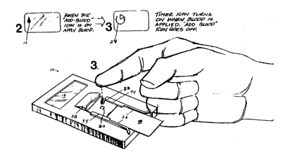
Figure 2 illustrates the addition of a drop of blood 22 to
a test strip positioned in the disposable electronic
diagnostic test instrument, and shows the prompt and
instructional icons 16 and 24, Figure 2, displayed on the
test instrument LCD display 18 during these steps.
Figure 3 illustrates the test instrument LCD display 18
with all prompt and instructional icons and all possible
cholesterol readings being simultaneously displayed
thereon, including:
a. a Clock icon 24 (~) on the meter's display which
indicates that the meter is operating and not waiting
for a user operation;
b. an Add Blood icon 16 (~)on the meter's display which
prompts the user to add a drop of blood onto the test
strip that has been fully inserted into the meter;
5 c. a Check Mark icon 26 (~) on the meter's display which
indicates a diagnostic mode of operation. This mode is
not used by a consumer but may be used by manufacturers
and quality control professionals to check the
performance or calibration of the meter;
SUBSTITUTE SHEET (RULE 26)
CA 0220~268 1997-0~-13
WO96/lS439 PCT~S95/15439
d. an Error icon 28 (ERR) on the meter's display which
indicates an error condition;
e. an Under 200 icon 30;
s
f. a 200 to 239 icon 32; and
g. an Over 240 icon 34.
The LCD displays one of four results as set forth in the
following Table l.
Table l
Meter Interpretation Meter DisplaYReadinq
Error ERR Defective Strip
Error ERRLess than l00 mg/dL
Desirable Under 200l00 to l99 mg/dL
Borderline 200 to 239200 to 239 mg/dL
High 240 & Over240 mg/dL or more
Figure 4 shows corresponding keying features of the test
strip 12 and the test instrument l0, Figure l, for properly
positioning the test strip in the test instrument. The
test strip shape combined with features in the instrument
housing provides for self-location of the test strip in a
test aperture provided on the instrument housing. The
instrument includes positional guides for ensuring that the
test strip is properly positioned with respect to the
instrument, which include two lateral edge guides 36 for
engaging two lateral edges of the test strip 12 and an
SUBSTITUTE SHEET (RULE 26)
CA 0220~268 1997-0~-13
WO96/15439 PCT~S95115439
angled fore guide 38 for engaging a corresponding angled
fore edge tab 40 of the test strip, as shown more clearly
in Figure 4. The angled tab 40 is positioned off-center
with respect to the chemical test strip, such that the
angled tab 40 of the chemical test strip 12 can properly
engage the angled fore guide 38 only when the chemical test
strip 12 is properly positioned in the instrument housing,
not in a reversed or upside down position. A test strip
sensor switch 42, Figure 6, is located adjacent to the fore
guide 38 for activating the first control circuit in
response to a test strip 12 being placed in the electronic
diagnostic instrument lO, Figure 1.
The lateral edge guides 38 are supplemented by hold down
. 15 tabs 44, Figure 4, for properly positioning the test spot
area 20, Figure 2, on the chemical test strip 12, on which
one or more drops of blood to be tested are inoculated,
relative to a test reading aperture 46, Figure 6, in the
instrument. The aperture 46 has therebelow a test area in
which a light emitting diode 48, Figure 6, is positioned to
emit radiation toward the test spot 20, Figure 2, and a
silicon photodiode 50, Figure 6, is positioned to detect
radiation reflected by the test spot.
Figure 5 illustrates the optical detecting arrangement of
the test reading area of the instrument lO, Figure 6,
showing the positional relationships of several components
of the optical detecting arrangement. The electronic
instrument lO is designed with a planar sensor geometry in
which the LED emitter 48 and the photodiode detector 50 are
mounted on a circuit board 52 with their normal axes
SUBSTITUTE SHEET tRULE 26)
_
CA 0220~268 1997-0~-13
WO96/15439 PCT~S95/15439
-13-
parallel to the strip surface normal axis. In greater
~ detail, the light emitting diode 48 is mounted with its
longitudinal light emitting axis substantially
perpendicular to the planar surface, and the photodiode 50
is mounted spaced from the light emitting diode 48 with its
longitudinal light detecting axis also positioned
substantially perpendicular to the planar surface of the
circuit board 52. The LED emitter 48 is well diffused and
displaced from the detector to avoid detection of specular
reflections.
Some amount of stray room background light will be incident
on the detector 50. The amount of background illumination
is minimized by the illustrated mechanical design of the
. lS instrument and by the use of an optical bandpass filter 54,
Figure 6, having bandpass characteristics matching the
desired measured wavelengths of the LED 48, mounted over
the LED 48 and the photodetector 50 and beneath the test
strip 12. The effect of background illumination is further
reduced by sampling the detector signal level with the
emitter disabled and subtracting this signal from the
intended signal, as explained in greater detail hereinbelow
with reference to Figures 7 and 8.
Two factors that greatly influence the alignment tolerances
of the test strip.12 with respect to the test instrument
are the flare and specular contributions, as discussed
hereinbelow.
Internal flare is the signal due to reflected light from
surfaces other than the test strip 12, and has the effect
SUBSTITUTE SH EET (RULE 26)
CA 0220~268 1997-0~-13
WO96tlS439 PCT~S95115439
-14-
of reducing the apparent measurement contrast. Internal
flare is minimized through careful housing design and by
the selection of materials or coatings with low
reflectance. Residual internal flare value is measured at
the factory and stored in memory.
The sensitivity of the emitter/detector system to
specularity impacts upon the apparent contrast of the
measurement and might introduce measurement errors due to
the variability in the specularity of the test strip 12
(which is largely a function of how much blood is applied
thereto), which is minimized through careful design of the
geometry of the emitter/detector system.
Accordingly, the geometry of the emitter/detector system is
quite important to the accuracy of the measurement. One
selected geometry is a 3.75 mm separation between the LED
48 and the photodiode 50 (longitudinal axis to longitudinal
axis) and a 2.5 mm separation between the upper surface of
the circuit board 52 and the lower surface of the
instrument strip receiver housing. Contribution of the
specular image affects alignment sensitivity in the y
(left-right)and z (up-down) directions, and the
LED/photodiode separation (center to center) has been
selected to be 3.75 mm to reduce this sensitivity. A flare
screen 58 is also placed between the LED and the
photodetector 50 to reduce the flare contribution. The
flare screen 58 comprises a l.49 mm tall by 2.8 mm wide
flare barrier placed 0.8 mm from the center of the LED 48
to reduce the flare contribution, and also results in a
SUBSTITUTE 5HEET (RULE 26)
CA 0220~268 1997-0~-13
WO96/15439 PCT~S95115439
reduction in the alignment sensitivity in the x and y
directions in the sensor plane.
v Figure 6 is an exploded view of the electronic test
instrument, showing the electronic circuit board 52 and
other features of the test instrument. The test instrument
has all of the circuitry including the ASIC 60, the optical
components, and a power supply battery 55 mounted on a
single circuit board 52, which is mounted in an outer
housing 56.
The test strips 12 to be used with the disposable
electronic diagnostic instrument of the present invention
preferably are based upon the use of a dry reagent
lS chemistry. In dry reagent chemistry, the reagent chemicals
are stored in a dry state in a single device which also
incorporates a reaction chamber as part of the structure.
This integration of the different components has the
advantage of requiring much less automation or operator
intervention. Fluid contained in the sample activates the
test chemicals, and the matrix that holds the test
chemicals usually undergoes a color change that can be read
directly without further processing. The basic chemistry
involved in testing blood cholesterol levels is well known.
U.S. Patent 3,907,645 (Richmond) discloses a method and kit
for assaying cholesterol in a liquid. The disclosed
cholesterol assay involves incubating the liquid to be
tested with an enzyme preparation which is derived from
Norcardia species. The enzyme preparation oxidizes any
cholesterol present in the liquid into cholestenone and
SUBSTITUTE SHEET (RULE 26)
-
CA 0220~268 1997-0~-13
WO96115439 PCT~S95115439
-16-
hydrogenperoxide. The amount of cholesterol is determined
by measuring the amount of hydrogen peroxide produced.
The chemistry test strips used with the disposable
electronic diagnostics instrument of the present invention
can be of the type disclosed in U.S. patent application
Serial No. 08/115,946, filed September l, 1993, for a
DEVICE AND METHOD FOR CONDUCTING BIOLOGICAL ASSAYS
CONTAINING PARTICULATE SCREENING SYSTEM. That patent
application discloses a chemical test strip for conducting
biological assays which uses a particulate screening system
to remove contaminating substances from the biological
sample. The particulate screening system comprise~ a blood
separation matrix, a flow control hydrophilic screening
matrix, and a reagent matrix with at least one hydrophilic
microporous membrane having incorporated therein a
calorimetric detection system for an analyte. The device
is adapted to detect, and in some cases quantitatively or
semi-quantitatively measure, an analyte present in a
biological fluid so that a color change is observed when
the fluid is brought into contract with the reagent
membrane pad containing the detecting system. The system
is particularly suitable for glucose or cholesterol
detection devices where a small capillary blood sample is
preferred and presence of particulate matter in the
biological sample, most notably red blood cells, would be a
hindrance to the analytical results.
Figure 7 is an electrical block diagram of the electronic
control circuit for the test instrument, while Figure 8
illustrates in further detail the comparators and threshold
SUBSTITUTE SHEET ~RULE 26)
CA 0220~268 1997-0~-13
WO96/15439 PCT~S95/15439
adjustments of the electronic control circuit. The
electronic cholesterol disposable test instrument is
provided with an Application-Specific Integrated Circuit
(ASIC) 60, which is a custom designed integrated circuit
that controls the meter. The electronic system controls
the operation of the instrument and prompts the user
through the proper sequence of operational steps. The
custom mixed-signal ASIC 60 includes all of the electronics
for the first and the second control circuits to:0
control the Power-On Self-Test (POST), calibration and
cholesterol test sequencing;
drive the display 18, Figure 6;
drive the sensor 50/emitter 48;
process the sensor 50 detector signal; and
calibrate the unit.
The sensor system is controlled by the ASIC 60, and the two
primary components thereof, the light-emitting diode 48 and
the photodiode detector 50, and bare dice epoxy-mounted to
the circuit board 52, and connections to the ASIC 60 are
provided by traces on the circuit board.
The liquid crystal display 18, Figure 6, is controlled by
the ASIC 60 using a direct (non-multiplexed) drive mode to
reduce complexity. The LCD 18 clearly displays all user
prompts, status conditions, and qualitative test results in
a relatively small viewing area.
Figure 7 is a block diagram of the major components of the
control circuits as they are implemented in the ASIC 60. A
SUBSTITUTE SH EET (RULE 26)
CA 0220~268 1997-0~-13
WO96/15439 PCT~S95115439
-18-
Power Control circuit 62 shuts off power to the majority of
the circuitry when the device is in an IDLE mode. A
Measurement Control circuit 64 generates timing signals
used to pulse the LED 48 and to control a Black Subtraction
circuit 66, explained in greater detail hereinbelow. The
timing signals comprise three synchronous signals having
defined phase relationships and a period of approximately l
msec. An LED Drive circuit 68 provides the LED 48 with
approximately 5 mA current pulses. A transimpedance
amplifier 70 amplifies and buffers the signals from the
photodiode 50, and is a high gain, low noise circuit. The
photodiode 50 can be similar to Photnic Detector's part
PDB-VlOl, operated in a photovoltaic mode.
The Black Subtract circuit 66 samples the photodiode output
when the LED 48 is off and when it is on. These two sample
signals are low-pass filtered at 72, 74, and are subtracted
using a differential amplifier 76. The resultant signal
represents a signal normalized to eliminate the effects of
background radiation. In a Reference Circuit 79, a White
Sample circuit 78 samples and holds the output of the Black
Subtract circuit 66 prior to a user's addition of a blood
sample to the test strip 12, Figure 2. The sampled value,
along with the output of a calibration register 80, are
used by a reference generator 82 to generate a reference
voltage which is divided and supplied as three different
threshold voltage to three comparators at 84. The three
comparators at 84 compare the output of the Black Subtract
circuit 66 with voltages divided from the reference
voltage. The outputs of the comparators are supplied as
inputs to a State Machine 86. A Peak Detector circuit 88
SUBSTITUTE SH EET (RULE 26)
-
CA 0220~268 1997-0~-13
WO96/15439 PCT~S95/15439
-19-
senses when the slope of the output of the Black Subtract
circuit 66 has reversed. The Peak Detector 88 output is
supplied to the State Machine 86, which performs the logic
and control functions as described herein. Two one-shot
timers at 90 generate timing intervals for use by the State
Machine, at 5 +/- l minute and l5 +/- 5 minute intervals.
A multiplexer 92, under control of an MUX input signal at
94, controls the routing of the LCD_CAL[0:5] I/O lines at
96. During factory calibration of the instrument, the MUX
92 is driven active and calibration data on the test strips
is supplied on the LCD_CAL[0:5] lines 96 and directed to
the Reference circuit 79 where these values are programmed
into and stored in an OTP register 80. Each instrument is
calibrated for a specific chemistry lot prior to final
packaging. This calibration function is provided by the
ASIC, and includes a serial communications link to the
programming device. Calibration data is retained in a
static memory within the ASIC. During normal operation,
the State Machine outputs LCD[0:5] at 96 statically drive
the custom, six-segment LCD 18.
.
The various inputs and outputs illustrated on the left side
of Figure 7 have the following meanings.
Name DescriPtion
BAT 3V Lithium battery input
GND Ground connection
LED LED Drive Output
PDA Connection to Photodiode Anode
SUBSTITUTE SHEET (RULE 26)
,
CA 0220~268 1997-0~-13
WO96/15439 PCT~S95/15439
-20-
PDC Connection to Photodiode Cathode
AOUT Analog Output used for Test
LCD_CAL[0:5] Multiplexed LCD Drive Outputs/Inputs
for Programming Calibration Values
MUX Mux select for LCD_CAL[0:5]
PWREN Input from Power-On Contact
Figure 8 illustrates in further detail the signal
processing in which an output signal from the photodiode
detector 50 is amplified by transimpedance amplifier 70.
The Black Subtract circuit 66 samples (controlled by sample
timing signals Sl, S2 from measurement control circuit 64,
Figure 7) the amplified photodiode output when the LED 48,
Figure 7, is off and when it is on. These two sample
signals are low-pass filtered at 72, 74 and are subtracted
by the differential amplifier 76. The White Sample circuit
78 (controlled by timing signal S3 from measurement control
circuit 64, Figure 7) samples and holds the output of the
Black Subtract circuit 66 prior to a user's addition of a
blood sample to the test strip 12, Figure l. The sampled
value, along with a calibration input from calibration
register 80, is used by reference generator 82 to generate
a reference voltage which is then voltage divided (as by
resistor voltage dividers) to derive three reference
threshold voltages representative of >240, 200-239~ <200,
which are supplied to three comparators 84A, 84B and 84C.
The three comparators compare the output of the Black
Subtract circuit 66 with the voltages divided from the
reference voltage. A Peak Detector circuit 88 senses when
the slope of the output of the Black Subtract circuit 66
has reversed. The outputs of the comparators 84 and the
SUBSTITUTE SHEET (RULE 26)
CA 0220~268 1997-0~-13
WO96/15439 PCT~S95/15439
output of the Peak Detector 88 are supplied to the State
Machine 86, which performs the logic and control functions
as described herein.
Figure 9 is an operational flow diagram of the electronic
test instrument. The power circuit 62, Figure 7, normally
maintains the instrument in an idle mode 100, during which
power consumption is minimal and the display is blank,
block 101. The insertion of a test strip 12, block 102,
activates the instrument by the strip sensor switch 42,
Figure 6. The power control circuit 62, Figure 7,
automatically turns the instrument off when a test is
completed or when the test strip is removed in order to
reduce power consumption.
Full insertion of an undeveloped test strip initiates a
first control circuit with the Power-On Self-Test (POST)
sequence 104, which is a diagnostic routine automatically
performed when a strip is inserted to verify proper sensor
operation. The first control circuit is illustrated in
further detail in Figure 10. If the POST is passed, a
flashing add blood prompt icon 16, Figure 2, appears on the
display, block 116, Figure 9. If the POST is failed, one
of two possible error displays will result.
1. Referring to Figure 10, an ERR display at 108 indicates
that the underdeveloped test strip did not exceed the
Rw threshold.
0 2. An ERR and ~ display at 110 indicates that the
Instrument Verification test has failed.
SUBSTITUTE SHEET (RULE 26)
~ = ~
CA 0220~268 1997-0~-13
WO 96/15439 PCI~/US95115439
- 22 -
When the instrument is turned on, the POST sequence
illustrated in Figure 10 checks the reflectance of the test
strip at 106. If there is an optical or electronic failure
in the instrument, it does not accept the test strip and
reports an error without further testing. The instrument
also rejects all test strips that are too dark. Thus phony
strips, used strips, strips that were exposed to humidity
for long periods of time are rejected. After accepting the
test strip, the reference is adjusted for Rw at 112, and
the instrument next performs an internal "electronic check
strip" procedure at 114 in which the test strip is
illuminated with less energy, and the instrument verifies
that an appropriate signal is obtained from the detector.
If not, an ERR and ~ are displayed at 110.
Referring back to Figure 9, second control circuit takes
the control of the instrument when the POST sequence from
the first control circuit passed successfully. At this
point an add blood icon 16, Figure 1, is displayed at 116.
If no action occurs within 15 minutes, block 118, the
instrument displays ERR at 120. When blood has been
detected, the instrument proceeds to the Measurement
sequence by searching for a detected RMIN at 122. At the
beginning of the Measurement sequence, the flashing ~ is
disabled and (~) is displayed at 124.
When blood is detected, the instrument has 4 minutes to
detect RMIN, block 126. If RMIN is not detected within 4
minutes, the instrument checks if the measured result is
greater than the 240 threshold, block 128, and if not, ERR
is displayed, block 120. This means that a maximum color
,
SUBSTITUTE SHEET (RULE 26)
CA 0220~268 1997-0~-13
W096/15439 PCT~S95/15439
-23-
was not detected within 4 minutes, but the result obtained
at 4 minutes indicates less than 240 mg/dl cholesterol. In
this manner, the instrument is able to reject strips that
have lost so much activity (age or unusual exposure) that
they are unable to achieve the end if reaction within 4
minutes. If the reflectance is greater than the 240 mg/dL
threshold, the instrument displays the 240 ~ Over result at
130.
If the peak detector`circuit detects RMIN, the result is
determined by comparing the measurement against the 100
mg/dL and 200 mg/dL thresholds, block 132, and one of the
following results is displayed:
a. If the measurement is less than the 100 mg/dL
threshold, block 134, ERR is displayed at 136. When an
insufficient amount of blood is added to the strip and
a part of the reading surface remains dry, the meter
will detect less than 100 mg/dl cholesterol and report
the error message;
b. If the measurement is greater than the 100 mg/dL
threshold and less then the 200 mg/dL threshold, block
138, Under 200 is displayed at 140; and
c. If the measurement is greater than the 200 but less
than the 240 mg/dL threshold, block 142, 220 to 239 is
displayed at 144;
0 d. If the measurement is greater than the 240 mg/dL
threshold, over 2~0 is displayed at 130.
t- SUBSTll~JTE SH EET (RULE 26)
CA 0220~268 1997-0~-13
WO 96/15439 PCI'JUS95tl5439
- 24 -
When the result of the test is displayed, the displayed
result will blink for 5 minutes. During that time, the
user will be able to remove the test strip from the meter
for an inspection. The instructions illustrate examples of
acceptable and unacceptable strips, providing the user with
the ability to accept or reject the result.
If during the above procedure the strip is removed and the
instrument senses that the Power Enable switch is not
activated, the meter returns to an IDLE state controlled by
the first control circuit.
The electronic cholesterol disposable test instrument can
also be provided with a Static Diagnostic Test (SDT), which
is a diagnostic routine that involves placing a special
diagnostic strip in the unit. The Static Diagnostic Test
(SDT) is initiated by the user performing the following
sequence:
l. The white check strip is fully inserted while the
instrument is in the idle mode;
2. When the flashing ~ appears on the display, the white
check strip is removed and the SDT check strip (which
does not activate the Power Enable switch) is inserted.
At this time, all icons are disabled.
During the SDT, the instrument tests for the first three
possible events;
~l)BSTrlUTE SHEET (RULE 26)
~,.~.. .. ~ ,
CA 0220~268 1997-0~-13
WO96/15439 PCT~S95/15439
-25-
l. If operator inserts a normal test strip, the Power
~ Enable switch is activated, in which case the first
control circuit is in1tiated with the POST test;
2. If operator inserts an SDT check strip, the result is
displayed provided that the Power Enable switch is not
activated;
3. If no action occurs within l0 seconds, the instrument
returns to the idle state and all displayed icons are
disabled.
When any result or graphical icon is displayed, the icon is
flashed until one of two events occurs:
l. The user removes and inserts a strip, in which case the
instrument initiates the POST sequence;
2. If no action occurs within 4 minutes, the icon is
displayed steadily and the instrument waits for one of
two events to occur:
a. If the user removes and inserts a strip, the POST
sequence is initiated;
b. If no action occurs within 15 minutes, the
instrument returns to the idle mode and all
displayed icons are disabled.
The instrument is easy to hold (approximately credit card
length and width), allows right- or left-handed use, and
SUBSTITUTE SHEET (RULE 26)
CA 0220~268 1997-0~-13
WO 96/15439 PCTIUS95/15439
- 26 -
the display provides an unmistakable result, easily read in
average ambient lighting.
While several embodiments and variations of the present
invention for a disposable electronic diagnostic instrument
are described in detail herein, it should be apparent that
the disclosure and teachings of the present invention will
suggest many alternative designs to those skilled in the
art.
SUBSTITUTE SHEET (RULE 26)