Note: Descriptions are shown in the official language in which they were submitted.
CA 02205302 1997-OS-13
WO 96115642 PGTIEP95104509
1
Tatle
Dynamic Channel Allocation for Sectorized Radio Access Units
of a Mobile Communication System
... ~
Field of the inve~ation
The present invention relates generally to
telecommunication systems comprising a radio link connection
between two or more telecommunication units and, more
specifically, to telecommunication systems having a plurality
of geographically spread fixed and/or mobile radio
telecommunication units:
Backoround of the invention
In conventional Public Switch Telephone Networks (PSTN) and
Integrated Services Digital Networks (ISDN), for example, up
till now the overwhelming majority of residential and office
subscribers have a wired connection from the subscriber premises
to a public local exchange. These subscriber connections, which
may run via an intermediate concentrator, are referred to as the
local loop.
The installation of such wired links all the way to the
subscriber premises is both time consuming and involves
substantial networking costs, apart from troubles caused by the
interruption of streets and pavements. Therefore, there is a
growing interest in replacing the wired local loop by a so-
called wireless local loop; i.e. using radio technology as an
alternative for or as a replacement of the copper wires down to
the subscriber premises. This is not only of interest for the
present network operators in case of expansion or renovation of
the existing public telecommunication network but, in
particular, for new operators which would like to provide
competitive public telecommunication services, such as a public
telephone service. The concept of wireless public subscriber
connections is called Radio in the Local Loop (RLL).
CA 02205302 1997-OS-13
GVO 96/I5642 PCTlEP95104509
2
Within the concept of RLL, two basic systems can be
distinguished: Fixed RT-T~ (FRLL) and Mobile RLL (MRLL). In the
FRLL system, the subscriber is provided with an ordinary~.
telephone socket, however connected to a radio transceiver, also
called Fixed Access Unit (FAU) or Wireless Fixed Access Unit'.
(WFAU). Via this FAU/WFAU a radio link is established with a so-
called radio access unit, which provides access to the
PSTN/ISDN. In the MRLL concept, the subscriber is provided with
a portable cordless or mobile radio telephone handset, by which,
via the radio access unit, direct access to the PSTN/ISDN can
be established.
Mixed concepts are also possible, i.e. FRLL providing
mobility in the subscriber premises, also called Cordless In The
Home (CITH) and residential or neighbourhood mobility, also
called Cordless In The Neighbourhood (CITN). In some countries,
governmental regulations prevent the established telephone
operators from offering local mobility in the present PSTN/ISDN.
In such cases, it is very advantageous for a second or third
operator to offer both fixed and mobile or cordless access to
the PSTN/ISDN.
Other types , of communication systems having wired
connections to a PSTN/ISDN are the we..-k..~.cwr: cellular mobile
telephone and data transmission systems. A typical cellular
mobile communication system comprises mobile radio subscriber
units, a plurality of radio base stations, each providing
service to a geographical area or cell, and radio exchanges or
mobile telephone switching offices (MTSO) to which a number of
base stations are connected. The MTSO are in turn coupled to a
PSTN/ISDN for completing transmissions, such as telephone calls,
between mobile radio subscribers and landline subscribers.
Cellular systems provide coverage over relatively wide
areas, i.e. relatively large cells. Analogue cellular systems,
such as designated AMPS, ETACS, NMT-450 and NMT-900 have been
deployed throughout the world. Digital cellular systems are
designated IS-54B in North America and the pan-European GSM
system. These systems, and others, are described, for example,
CA 02205302 1997-OS-13
R'O 96/15642 PGTJEP95104509
3
in the book titled ~Cellular Radio Systems~, by Balston et al.,
published by Artech House, Norwood, MA., 1993.
First generation cellular mobile networks provide service
to macrocells,-having a range of 1 to 5 km from the base station
to the cell boundary, and large cells (5 to 35 km), with some
azt_oa.lit:o cnlln- f > u00 Icm) . 11« imPorCarW problnm .Lm w.f..rnlnau
cellular communication is to provide full coverage cost
effectively. This has lead to the splitting of cells in dense
traffic areas, adding microcells (10 to 400 m for pedestrians
and 300 m to 2 km for vehicles) and minicells (500 m to 3 km)
overlaid by a macrocell structure. The overlaying macrocells
serve low-traffic areas and address cell crossings by mobile
subscribers.
Future cellular mobile networks will also have picocells
(a few meters) and nanocells (up to 10 m), often in clusters of
street microcells, with each cluster overlaid by a macrocell.
In a typical cell overlay configuration, each microcell has its
own base station providing service to the corresponding cell,
whereas the several base stations are wired to a concentrator
or access unit which is in turn coupled to a MTSO. In particular
in a picocell and nanocell environment these wired links or
loops involve substantial networking costs, not contributing to
the object of providing cost effective cellular mobile coverage.
Accordingly, in such cellular overlay mobile networks it
would be advantageous to replace the wired links between the
several base stations of micro=, nano- and picocells and the
corresponding access unit by wireless links, hereinafter
referred to as wireless multicell links (WML).
The advantages of wireless local loop connections in the
PSTN/ISDN and wireless multicell links in a cellular mobile
network are numerous, ranging from short installation times,
increased flexibility and improved operation and maintenance of
the network to the opportunity of providing-local subscriber
mobility to the PSTN/ISDN.
. CA 02205302 1997-OS-13
' _ ; - : _. '
P06636W001 ". . q ,_, .,..,
International Patent Application WO 94/19877 discloses a
RLL systam.based on the existing business cordless technology,
such as -designated CT2, CT3 and Digital European Cordless
Telecommunications (DECT), now called Digital Enhanced Cordless Tele
communications (DECT).
These ve=..y low power, high communication capacity systems
consist of a plurality of geographically spread radio access
units or base stations. Each radio access unit comprises a radio
access module having radio transceiver means and antenna means
providing a plurality of radio communication channels to remote
telecommunication units in a cell.. The various radio access
units are connected to a radio exchange, which is in turn
coupled to a private or public telecommunication network. Each
radio access module is further provided -with control means
arranged to co-operate with the remote telecommunication units
for-adaptively selecting a free communication channel which,
when occupied, is individual to a radio link connection between
the radio access-unit and a particular remote telecommunication ,
unit. This type of access technique is known as Dynamic Channel
Allocation {DCA).
These cordless communication systems have been developed
for use in pico-, nano- and microcell applications. In order to
cover extensive residential or metropolitan areas, a very large
number of access units or base stations have to be installed and
maintained. The building of an infrastructure for the
installation and interconnection of such a large number of
access units can be rather costly.
A paper by I.Brodie, titled "Performance of Dynamic Channel Assignment
Techniques in a Cellular Environment", I992 IEEE International Conference
on Selected Topics in Wireless Communication", June 25-26 1992 Vancouver,
B.C., Canada, discloses a radio access unit or base station for establis-
hing radio link connection with a plurality ofgeographicall,y spread remote
telecommunication units in a cell of a cellular mobile radio communication
system. The radio access unit comprises transceiver and control means and
antenna means for establishing radio link connections in accordance with
the DCA type of access technique described above. The transceiver and
control means and antenna means are arrangedt~, transmit in directionally
AtviENDED SH
CA 02205302 1997-OS-13
P06636W001-. , $ . . , . .. "
separate geographical transmission sectors and are positioned such that
a resulting omnidirectional (360 0 coverage is obtained.
This known access unit is arranged such that a plurality of common
radio communication channels is available for each of the sectors. However,
as described by Brodie, no radio communication channel may be used twice
on the same radio access unit even in different sectors. Accordingly, the
maximum number of radio communication channels available for radio communi-
cation in a cell is limited to the plurality of common radio communication
1o channels available to the radio access unit or base station of the cell.
It will be understood that a large amount of control equipment and
processing is needed in order to operate a RLL system or WML in a pico-,
nano- or microcel7 overlay mobile network with an access unit such as
zs disclosed by Brodie.--In particular if more than one access unit provides
coverage to a particular sector. Further, not all of the potential
communication channels of the system can be made available at each access
unit and transmission sector, with the result that the overall traffic
handling capacity is not as efficient as required to provide a viable RLL
2o system or WML in a cellular mobile network system for use in residential
and metropolitan areas.
An essential requirement for RLL and 47ML cellular mobile
network systems is, however, enabling-installations which are
economic as to capacity and power. That is to say, the various
25 -components of the system have to be designed such that an
optimum between geographical coverage, range, communication
capacity and installation costs can be achieved, in order to
provide competitive wireless connections.
30 Summary of the Invention
In view of the foregoing background, with regard to the
optimization of capacity and power, the radio access structure
and in particular the radio access units are critical elements
35 to provide a W able RLL system or WML -in a pico-; nano- and
microcell overlay cellular mobile network.
Accordingly, it is an object of the present invention to
provide a radio access unit for establishing radio link
Al:rENDED SHEET
CA 02205302 1997-OS-13 ~~_-;i~,.'~iu~ ~.-;r.~. r r -.
' A.r~ Jy~:~.. m, a K~ $ ~1 I
' i PCT Cfi%A'P,~~ji~~i
:0 2.
P0663GW001 6 -"
connections with a plurality of geographically spread remote
telecommunication units, in particular remote telecommunication
units of a RLL system or a multicell overlay cellular mobile
communication system.
It,is also an object of the present invention to provide
a RLL system, using the radio access unit of theinvention.
It is a further object of the present invention to provide
l0 a cellular mobile telecommunication system,~ using the radio
access unit of the present invention.
In a first embodiment, the invention provides a radio access unit
for establishing radio link connections with a plurality of geographically
spread remote telecommunication units, the radio access unit comprising
transceiver and control means and antenna means operatively connected to
provide a plurality of common radio communication channels in directionally
separated transmission sectors, the radio transceiver and control means
and antenna means are arranged to co-operate with the remote telecommunica-
tion units .in a transmission sector for adaptively selecting a free radio
communication channel of the plurality of common radio communication chan-
nels, wherein the radio transceiver and control means and antenna means
are arranged to select in each of the transmission sectors a free radio
communication channel of the plurality of common radio communication chan-
nels, which radio communication channel, when selected, can be reused in
the same radio access unit but is individual to a radio link connection
in a transmission sector.
The invention is based on the insight that optimization as
to capacity and power can be achieved through the combined
measures of sectorizing and dynamic channel access (DCA).
By sectorizing, the effective range of a radio link
connection can be extended. That is to say, by radiating the RF
power- of a transmitter means into a directionally limited
geographical are, the effective range of the radio transmitter
can be extended compared to omnidirectional coverage. By
reciprocity, the same.holds for the reception sensitivity of the
receiver means. Further, by using DCA as the channel access
technique for each remote telecommunication unit and radio
>4AFF_'lycr; ry.~~
CA 02205302 2005-10-24
7
access module in a given sector, all the common radio
communication channels of the system can be reused from sector
to sector, without the basic need for a channel or frequency
planning. This, because the DCA algorithm automatically prevents
the seizure of already occupied communication channels of a
sector or a cell.
Accordingly, with the access unit of the present invention
a RLL system can be build by installing a relatively small
number of access unit compared to the system.proposed by WO
94/19877, though increasing the communication capacity
compared to the access unit disclosed by Brodie.
By using the access unit of the present invention in a
cellular mobile network for providing' wireless connections
between several small cell base stations and a concentrator or
MTSO, a very flexible, economic, and high traffic handling
system can be obtained.
In a practical embodiment of the invention, the radio
access unit comprises a number of radio access modules, each
having radio transceiver means and control means arranged to
provide a plurality of common radio communication channels. The
access modules are operatively connected to the antenna means
for providing the common radio communication channels tv the
separate transmission sectors. The various radio access modules
may operate independently from each other, without any need for
control equipment or the like.
Accordingly, the radio access unit of the invention can be
advantageously assembled of independently operating access units
or base stations designed for operation under. the existing
business cordless technologies, such as CTZ or DECT, both of
which use DCA as their channel access technique. It will be
wunderstood that the access unit is not limited to the use of
this type of radio access modules_ Other technologies providing
communication channels under the control of a DCA algorithm may
be also used.
CA 02205302 1997-OS-13
WO 96115642 PC1'1EP95J045D9
8
By a suitable positioning of the different radio access
modules, omnidirectional coverage of anarea or (overlay) cell
can be achieved, such that in each (overlay) cell and all its
adjacent cells, all the common radio communication channels of
the system are potentially available for-establishing a radio
Link connection.
It is important to notice that, from a system point of
view, an omnidirectional radio access unit according to the
l0 invention assembled of radio access modules operating in
accordance with one of the present business cordless
technologies using DCA as their channel access technique,
operates itself identical to'a single omnidirectional radio
access unit or base station of -such business cordless
technology, however providing extended coverage and
communication handling capacity.
As mentioned above, the DCA algorithm occupies only free
channels in a given geographical area. A required amount of
redundancy, both for repair and maintenance purposes and to
account for an increase in the communication capacity for a
given sector, can be easily achieved in a further embodiment of
the invention, by providing the common radio communication
channels in a given sector by at least two radio access modules
of the unit, which radio access modules may operate
simultaneously during normal operation.
Although two or more access modules can be assigned to the
same sector, in a yet further embodiment of the invention the
antenna means are designed for overlapping sectorized coverage.
In a preferred embodiment of-the invention, the antenna
means comprise an arrangement of individual antennas,
operatively connected to the radio transceiver means of a
separate radio access module.
In order to provide as less as interference between the
several radio access modules of the radio access unit, the
antennas are preferably of a so-called isolated type, having
CA 02205302 1997-OS-13
WO 96115642 PCT/EP95104509
9
minimal side and backward radiation properties.
To this end, array antennas of the type having a plurality
of -radiating elements, each comprising a conductive patch
radiator above a conductive substrate, providing a microstrip
antenna having a radiating front side and a non-radiating or
shielded back side, have proven to be very suitable.
In the preferred embodiment of the invention, the antenna
means comprise a hexagonal arrangement of substantially 120
radiating microstrip antennas.
To provide for so=called switch diversity, in order to
select a more proper propagation path in case of interferences,
in a yet further embodiment of the invention the transceiver
means of each radio access module comprise switch means for
operatively connecting the transceiver means. to a first or
second antenna arrangement.
In order to prevent interferences while communication
between the access unit and a remote telecommunication is
established and in progress, the access L..~..t according to-the
invention operates preferably using a.~. improve-? D:A technique,
called Continuous.Dynamic Channel Seie=t:o.-. CDCS). The basic
property of CDCS is that a radio co--;:..~._catior, channel is
selected which is least interfered at the moment of its
selection.
Accordingly in a further embodiment of the invention, the
control means of the radio access modules are arranged to co-
operate with the remote telecommunication units in the
associated transmission sector for continuously adaptively
selecting a free communication channel amongst the plurality of
common communication channel of the system. The radio access
modules and remote telecommunication units preferably comprise
transceiver means, arranged to provide a plurality of
communication channels based on a multiple access technique,
such as Time Division Multiple Access (TDMA), Frequency Division
Multiple Access (FDMA) and Code Division Multiple Access (CDMA),
CA 02205302 2005-10-24
for example. 10
In the preferred embodiment of the invention, the radio
access modules and the remote telecommunication units operate
in accordance with the Digital Enhanced Cordless
Telecommunications (DECT) standard.
A more elaborated discussion on DCA and CDCS can be found
in US Patents 4,628,152; 4,731,812 and a paper by D. P.kerberg,
"Novel Radio Access Principles Useful for the Third Generation
Mobile Radio Systems", The Third IEEE International Symposium
on Personal, Indoor and Mobile Radio Communication, Boston
Massachusetts, October 19-21, 1992, which are included here by
reference.
In a constructional embodiment, the radio access unit of
the invention comprises a frame having parallel, longitudinally
spaced apart first and second mounting plates and means for
mounting the antenna substrates at and between the mounting
plates. These mounting means may comprise snap fitting means,
wherein the antenna .substrates or boards at opposite edges
thereof are provided with protrusions and the mounting plates
are provided with corresponding openings, such that in the
mounted state the protrusions are received in these openings.
In case of mounting of the radio access unit at relatively
high buildings, towers or the like, for antenna direction
purposes, means~for controlling the elevation of the antenna
boards are provided. Although these means may comprise (remote
controlled) driving means such as motors, gear wheels and the
like, in a yet further embodiment of the invention, the mounting
plates are provided with a number of radially spaced openings,
such that the antenna substrates can be mounted in a tilted
manner with respect to the mounting plates.
The invention relates also to a radio in the local loop
system, and a cellular mobile network, comprising a plurality
of geographically spread radio access units of the invention as
described above.
CA 02205302 2005-10-24
l Oa
According to a further aspect of the invention, there
is provided use of the radio access unit of the present
invention in a Radio in the Local Loop System, comprising a
plurality of geographically spread radio access units for
establishing radio link connections with a plurality of
geographically spread remote telecommunication units, the
radio access units each being connected via an intermediate
radio exchange to a public telecommunication network.
According to a further aspect of the invention, there
is provided use of the radio access unit of the present
invention in a cellular mobile telecommunication network,
comprising a plurality of geographically spread radio
access units for establishing radio link connections with a
plurality of geographically spread remote telecommunication
units providing service to a particular cell of the
network, the radio access units being connected via an
intermediate radio exchange to a public telecommunication
network.
CA 02205302 1997-OS-13
WO 96115642 p~.~~~9
11
The above-mentioned and other features and advantageous of
the invention are illustrated in the following description with
reference to the enclosed drawings.
Brief Description of the drawings
Fig. 1 shows, in a very schematic manner, a prior art RLL
system providing both FRLL and MRLL.
Fig. 2 shows, in a very schematic manner, a typical prior
art cellular mobile telecommunication system.
Fig. 3 shows, in a 'very schematic manner, part of cellular
system according to Fig. 2, in which several smaller cells are
overlaid by a larger cell.
Fig. 4 shows a schematic, partly sectional view of an,
embodiment o~ the radio access unit according to the present
invention.
Fig. 5 shows a schematic view from the line V-V of the
access unit Fig. 4.
Fig. 6 shows, in a very schematic manner, transmission
sectors formed by the radio access unit according to the present
invention.
Fig. 7 shows schematically a prior art stripline antenna
board used in the radio access unit of Fig. 5.
Fig. 8 shows a block diagram of a prior art radio module
used in the radio access unit of Fig. 5.
Fig. 9 shows, in a very schematic manner, an application
of the radio access unit according to the present invention in
a cellular multicell overlay mobile network.
CA 02205302 1997-OS-13
wo vsiissaz rcr~rvsioaso9
12
Detailed Description of the Embodiments
Without the intention of a limitation, the invention will_
now be described and illustrated with reference to an exemplary
-embodiment.
Fig. 1 shows an example of a RLh telecommunication system
providing fixed (FRLL) and mobile (MRIah) access, such as
disclosed by International Patent Application WO 94/19877. The
system is generally designated with reference numeral 1 and
comprises a plurality of radio access units or base stations 2,
each comprising a radio transceiver unit, the transceiver output
of which is connected to.a receive/transmit antenna 3. The base
stations 2 are further coupled to an exchange or switch 5, for
connection to a public telephone. and/or data network
(PSTN/ISDN). Although the connections to the exchange 5 are
shown. in the form of a cable 6, i.e. a copper wire or an optical
fibre, this may be also a microwave link, for example.
The system further comprises a number of remote wireless
fixed access units (W)FAU 7, comprising a radio transceiver unit
connected to a receive/transmit antenna 8, for establishing a
radio communication link 15 with a base unit 3. The remote units
7 comprise either one or both a telephone terminal 9, for
connecting an ordinary wire-type telephone 11 and a further
receive/transmit antenna I0. As illustrated, the remote units
7 are fixedly installed in - (orat) a building 12, such as a
house or the like. The antenna 8 may be an indoor or outdoor
antenna, preferably a long range antenna, whereas the further
antenna l0 is generally an omnidirectional indoor antenna.
Besides fixedly installed remote units 7, the system
comprises also several mobile remote units- 13, in the form of
telephone handsets, for example. These mobile remote units 13
35. each comprise a transceiver unit, one end of which is connected
to a receive/transmit antenna 14 and another end of which is
connected to a microphone/loudspeaker arrangement for voice
communication, for example. As illustrated, these mobile remote
units 13 can be used inside the building 12, to establish a
CA 02205302 1997-OS-13
WO 96115642 PCllEP95/04509
13
radio link 16 with the fixed remote units 7, via the indoor
antenna 10 and the mobile antenna 14, or for establishing a
direct radio link l7 with a base unit 2, via their respective
antennas 3 and 14.
In case of base stations 2 operating in accordance with the
existing low power cordless technologies such as designated CT2,
CT3 and DECT, each of these base stations covers a limited area
having the size of a pico-, nano- or microcell. Accordingly, a
large number of such base stations 2 have to be installed and
connected to the exchange 5 in order to cover extensive
residential or metropolitan areas, for example.
Fig. 2 shows a typical cellular mobile telecommunication
IS system, generally designated with reference numeral 20. The
system includes one or more mobile radio stations or units 21,
shown in the form of a car, one or more radio base stations 23,.
illustratively depicted in the from of a tower, and a radio
exchange or mobile telephone switching office (MTSO) 25.
Each mobile radio unit 21 comprises a transceiver unit, one
end of which is connected to a receive/transmit antenna 22 and
another end is connected to a microphone/loudspeaker arrangement
for voice communication, for example. Each base station 23
comprises a radio transceiver unit, the transceiver output of
which is connected to a receive/transmit antenna 24, and
provides service to a cell 26. The radio base stations 23
connect via a wire or cable 27 to the MTSO 25 which connects in
turn to a PSTN/ISDN 28 providing service to landline
subscribers, represented by a wired telephone 29. Through the
cellular network 20, a duplex radio communication link 30 may
be effected between two mobile stations 2i or, between a mobile
station 21 and a landline subscriber 29.
Although only three cells 26 are shown in Fig. 2, a typical
cellular network may comprise hundreds of base stations 23,
thousands of mobile stations 21 and more than one MTSO 25. The
cells 26 are of the size of a macrocell or a large cell.
CA 02205302 1997-OS-13
R'O 96/15642 PCf/EP95104509
14
In order to increase the traffic handling capacity of a
cellular mobile network within a given area, it is necessary to
decrease the cell size. Fig. 3 shows a typical embodiment of a,
cellular mobile network, in which a number of relatively small
cells 32, such as picocells, nanocells and microcells are-
contained within or overlaid by a relatively large cell, such
as a macrocell 31. For simplicity the various cells are depicted
in circular form, whereas just one macrocell is shown comprising
several smaller cells.
Each smaller cell 32 comprises a radio access unit 33
providing service to the mobile units 21 in the particular cell
(see Fig. 2). The various access units 33 are linked by a cable
34, such as a coaxial cable or copper wires, to a concentrator
unit 35 which is in turn coupled to the MTSO 36 of the
overlaying macrocell 31. In particular in dense residential or
metropolitan areas, a large number of small cells 32 may be
required, involving relatively high networking costs owing to
the wired connections 34.
Although it is conceivable to replace the wired multicell
links 34 by wireless links IS as shown in Fig. 1, this still
does not solve the, problem of having to install a large number
o~ base stations 2, to establish a radio link with the various
geographically spread radio access units 33 of the cells 32.
A proposed access unit according to the invention, suitable
for use in RLL and WML in cellular mobile radio networks
providing extended coverage and°communication handling capacity,
will now be described.
Referring first to Fig. 4 there is shown a partly sectional
view of the radio access unit 40 according to the present
invention. The access unit 40 comprises a longitudinal frame
having parallel upper and lower metal mounting plates, 42
respectively 43, having reinforcement fins 41 transverse to the
plates 42, 43 which fins 41 are welded or otherwise fixed to an
intermediate metal stud or post 44. The post 44 has a concentric
relationship with respect to the mounting plates 42, 43. Between
CA 02205302 1997-OS-13
wo 9snssa2 rcrmrvsiaasos
is
the mounting plates 42, 43 at the circumference thereof a number
of radio access modules 45 and corresponding antenna boards 46
are arranged. These access modules 45 and antenna boards 46 are
mounted at opposite sides of an intermediate longitudinal metal
mounting element 47.
At their short sides, the mounting elements are provided
with spring loaded protrusions or pins 48. In the mounted state,
these pins 48 are received in corresponding openings 49 of the
IO mounting plates 42, 43, by virtue of their spring action. By
pushing the pins against the spring force, the mounting elements
47 can be easily released from the frame.
The frame and the mounted radio access modules 45 and
antenna boards 46 are covered by a plastic radome 50, consisting
of an upper portion 51 and a lower portion 52, as.shown. At the
upper portion 51 of the radome a closure element 53 is provided,
which connects over a hole in the centre of the radome for
receiving the post 44, such to prevent moisture from entering
the radome 50 via the post 44.
The post 44 generally has the form of a hollow shaft having
holes 54 in its boundary wall for receiving connecting cables
(not shown? of the radio access modules 45. Via mounting flanges
55 fixed to the upper and lower mounting plates 42, 43 the frame
and radome 50 can be fixed to a mast 56 using screws or other
clamping means.
Fig. 5 shows a view from the line V-V of the access unit
40 of Fig. 4, with the upper portion 51 of the radome 50 and the
upper mounting plate 42 partly broken away. The mounting
elements 47 have a general U-shaped cross sectional front side
57 for receiving the antenna board 46. At their back side 58,
the mounting elements 47 are provided with a pair of protrusions
58 for receiving-shank like mounting means 59 extending in
longitudinal direction of the frame elements 47 for fixing the
radio access modules 45. In the embodiment shown, the radio
access modules 45 are simply fixed to the mounting means 59 by
means of screws 60. The antenna boards 46 may be clamped to the
CA 02205302 1997-OS-13
1V0 96/15642 PC1YEP95/04509
16
mounting elements 47 or otherwise fixed by means of adhesive or
screws, for example (not shown).
As can be seen from Fig.-S, the flanges 55 are designed
such to be fit to a mast 56 having an. outer diameter which is-.
smaller than the inner diameter of the post 44. The resulting
space 61 can be used .for receiving connecting cables of the
radio access modules 45, i.e. for communication and powering
handling (not shown).
By fitting the pins 48 in the corresponding holes 49
positioned closer to the centre of either one of the mounting
plates 42, 43 the antenna boards 46 can be arranged in a tilted
position with respect to the post 44. This to set an elevation
angle for the illumination of a specific region, if required.
In a preferred embodiment of the access unit according to
the invention, the radio access modules 45 and their
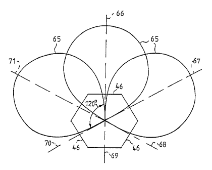
corresponding antenna boards 46 have a hexagonal arrangement
with one antenna board 46 per access module 45, thus providing
six transmission sectors 66, 67, 68 ,69, 70, 71 as schematically
shown in Fig. 6. '
The- antennas each have a substantially 120° radiation
pattern 65. Accordingly, 120° degrees transmission sectors are
formed, such that omnidirectional. coverage (360°) can be
provided by three non adjacent antennas 46, e.g. sectors 66, 68,
70. By adding another 'layer' of 120° antennas, i.e. sectors 67,
69.and 71, overlapping coverage of the adjacent transmission
sectors is achieved, thereby providing redundancy.
For simplicity the radiation patterns of only three sectors
haven been shown. A skilled person will be understood that even
more or less transmission sectors can be formed, dependent on
the coverage area and the communication load in such area.
Microstrip antennas having an array of radiating patches
are very suitable for the purpose of the present invention. Fig.
7 shows a prior art microstrip antenna 75, which includes a
CA 02205302 1997-OS-13
WO 96/15642 PGT/EP95/04509
17
plurality of conducting patches 76 above a conducting surface
77. The patches 76 are isolated from the surface 77 by a non-
conducting intermediate layer 78. The patches 76 are series
connected by striplines 79 and form radiating antenna dipoles.
At the top of the antenna 75 an antenna terminal 80 is formed,
for connecting the patches to the RF transceiver terminal of a
radio access module. The conducting surface 77 has to be
connected to a ground terminal of the transceiver, and forms a
non-radiating or isolated or shielded back-side.
The microstrip antenna 75 has a very low radiation to its
back side and edges, such that these antennas can be arranged
in a hexagonal shape, 'for example, with no or virtually no
coupling of RF energy between adjacent antennas. The leakage of
RF energy to adjacent antennas is less than 60 dB, even without
additional measures such as adding RF resistive material between
adjacent antennas. Accordingly, cross-modulation effects between,
adjacent radio access modules are negligible when using these
microstrip antennas 75. Reference is made to International
Patent Application W094/11958.
As already mentioned in the introductory part to the
present invention, the radio access unit according to the
invention can be assembled from radio access modules operating
in accordance with one of the present business cordless
technologies, such as designated CT2, CT3 and DECT, all using
DCA for accessing one of a plurality of common radio channels.
Fig. 8 shows a block diagram of a radio access module 45,
which operates in accordance with the DECT standard. In short,
DECT is a Multi Carrier/Time Division Multiple Access/Time
Division Duplex (MC/TDMA/TDD) digital radio access technique,
providing ten radio carriers, each divided into 24 time-slots
which serve 12 duplex communication channels, called a frame.
The base station 45 has a wired connection 81 to a local
exchange. This is a trunk or a multiline connection for up to
12 simultaneous telephone calls. Via an interface 82 are these
calls transcoded into ADPCM formate by speech codecs 83. Central
CA 02205302 1997-OS-13
R'O 96/15642 pGTlEp99~04509
18
control and application logic 84 detects incoming calls and
controls outgoing calls, and selects suitable combinations of
carrier and time slots in accordance with the DCA/CDCS_
algorithm, and merges via a multiplexer 85 the different
connections and time slots. The module 45 has a frame and slot-
synchronization unit 86 which controls slot reception and
transmission timing. The central control logic 86 also controls
a Transmit/Receive (T/R) switch 87 and an antenna diversity
switch 88, if antenna diversity is implemented. With antenna
diversity, if a radio connection provides no good communication,
the control logic first tries the other antenna before changing
the radio communication channel.
The radio interface of the module 45 consists of a
receiver/demodulator 89 and a transmitter/modulator 90.
Synchronisation and control information is stripped from
received data by unit 91, whereas such information is added to
the data to be transmitted by unit 92, connected as shown.
In the case of a mobile unit 13 shown is Fig. 1, for
example, the line connection 81 terminates in a microphone/
loudspeaker arrangement.
In accordance with the present invention, each of the 120
radio channels of the unit 45 are provided to each of the
sectors 66 - 71, shown in Fig. 6. Remote telecommunication
units, such as the (W)FAU 7 and the mobile units 13, shown in
Fig. 1, or the radio access units 33 of the cellular overlay
mobile network shown in Fig. 3.in either one of a transmission
sector 66 - 71 may now, in accordance with the DCA/CDCS
technique, select any of these 120 channels for communication
purposes, provided such channel is not used by another radio
link connection in said sector, whether or not processed via the
same radio access.module 45. After selection, such channel is
individual. to the established radio link connection.
Each of the wired connections 81 of-the radio modules 45
of'-the radio access unit according to the invention may be
separately connected to the PSTN/ISDN network. However, it is
CA 02205302 1997-OS-13
WO 96115642 PGT/EP95/04509
19
preferred to connect the radio modules to a so-called Node
Control Unit (NCU) which act as a traffic concentrator to the
PSTN/ISDN network. This NCU may be installed in the access unit
itself, for example mounted at the frame of the access unit 40
shown in Fig. 4 or in a separate housing.
In general, the radio access modules shown in Fig. 4 need
not necessarily be mounted at or near the antenna boards 46.
Like the above-mentioned NCU, these modules may also be
installed in a separate housing at the end of the mast 56, for
example. Such that the access unit 40 only houses the various
antenna boards 46: As will be understood by those skilled in the
art, various antennas can be used for the purpose of the present
invention.
With the access unit according to the present invention,
a RLL system can be provided by simply replacing some of the
base stations 2 by a radio access unit 40 according to the
invention. Of course, taking into account the extended coverage
and capacity of these radio access units. Diversity can be
achieved through -the- installation, -near to each other, of
several radio access units according to the invention, such that
they essentially cover the same region. Instead of complete
access units 40 as shown in Fig. 4, it is also conceivable to
make clusters of radio access units 40, having-access modules
45 as-shown in Fig. 8, and access units simply comprising
antenna boards 46, as mentioned above. To achieve polarisation
diversity, for example, the antenna boards may radiate with
different polarisation. In such case, the radio access units may
be mounted on the same mast on top of each other in a tandem
configuration, for example.
Fig. 9 shows an application of the radio access unit
according to the present invention in a multicell cellular
overlay mobile network.-By positioning the radio access unit 40,
for example, at the point of intersection of the macrocells 31,
arid connecting same with the MTSO 36 of the macrocells 31, a WML
37 with the remote access units 33 of each small cell 32 can be
established via the access unit 40. It will be understood that
CA 02205302 1997-OS-13
R'O 96/15642 PCTIEP95I04509
this is a very efficient manner, without the basic need for a
channel or frequency planning, of connecting the various small
cells, because.the traffic generated thereby is generally very
low and temporarily, not justifying a wired link 34 as shown in
5 fig. 3.
The radio access unit according to the present invention
provides an excellent tool for the coupling of cellular GSM and
DECT wireless systems, for example.
Although the present invention has been described with
reference to a specific embodiment and a DECT communication
system, it will be understood that the novel idea of the present
invention can be used with several access technologies, such as
FDMA and CDMA, and many different embodiments of the radio
access unit.