Note: Descriptions are shown in the official language in which they were submitted.
CA0220~6231997-0~-16
METHOD AND APPARATUS FOR INTRAOSSEOUS INFUSION AND
ASPIRATION USING AN AUTOMATIC ~T~'T~T~'A~E MECHANISM
FIELD
The present invention relates to an apparatus and
method for infusing liquids into and to the aspiration of
the bone marrow from humans and ~n; m~ 1 s . In particular,
the present invention pertains to infusion and aspiration
of the bone marrow under emergency and field conditions.
BACKGROUND OF THE l~V~ l ION
Usually drugs and liquids are delivered to patients
through a catheter or intravenously at a peripheral blood
vessel. This method is satisfactory in cases where the
blood pressure of the patient is at normal levels.
However, when blood pressure drops, for example, during a
heart attack, drug overdose, or severe hemorrhaging, the
peripheral blood vessels collapse and access to these
vessels is difficult or impossible. In such cases, an
alternative to intravenous infusion is intraosseous
infusion. An intraosseous infusion apparatus may be used
to infuse drugs and other liquids into the bone marrow
under such emergency conditions. In particular, an
intraosseous device is used to penetrate the patient's skin
and the overlying subcutaneous layer on top of the cortical
layer of the bone, the cortical layer of the bone, and the
bone marrow, and to supply drugs or fluids directly to the
blood supply system of the bone. Typically, the sternum,
femur, tibia or other bone near the skin is used.
CA 0220~623 1997-0~-16
Intraosseous infusion can also be used on patients with
blood vessels that are hard to find and on young children
whose blood vessels are small and also hard to find.
Intraosseous infusion can also be used in emergency or
battlefield conditions where quick intravascular access may
make the difference between life and death. The caregivers
in these situations have low levels of training and need an
intraosseous device that is simple and rapid to use.
Although intraosseous infusion is a feasible
alternative to intravascular infusion, it has not met with
widespread acceptance and popularity for a variety of
reasons. One reason for this is the practical difficulty
in inserting the infusion needle to the proper depth in the
bone in order to access the marrow. One method to overcome
this problem has been to use a stop or marker on the needle
to indicate when the needle has penetrated to a particular
depth. This method has not been effective since it
requires an estimation of the required depth. Skin and
tissue thickness overlying the bone range from 3 mm to 25
mm. and thus the skin surface cannot be used as a reliable
reference point. A trained individual like a doctor would
be needed to determine the correct depth and insert the
intraosseous device. This can be difficult even for highly
skilled professionals. Another method to overcome this
problem has been to monitor the resistance to the
penetration of the infusion needle. The resistance is high
when the needle goes through the cortical layer of the bone
but decreases when it hits the bone marrow. This method is
CA 0220~623 1997-0~-16
not very effective since resistances may vary. Again, a
highly trained individual is required to advance the
intraosseous needle or tube slowly and feel for the changes
in resistance.
Intraosseous penetration of the cortical layer of the
bone to the bone marrow is also needed when a sample of
bone marrow from a patient must be taken. Again a needle
or tube must be inserted through the subcutaneous layer
into the bone so that the bone marrow can then be
aspirated. Again, only a highly trained individual can
accurately determine the depth of the penetration of the
tube or needle into the bone marrow.
In U.K. Pat.No. 1,315,796, issued to Pashenichny et
al., a device for intraosseous injection is disclosed
consisting of an outer tube with a screw and a male thread
on one end and an inner tube fitted into the outer tube.
The device is drilled into the osseous tissue, the inner
tube is removed and a cannula is connected to the outer
tube. U.S. Pat.No. 4,969,870, issued to Kramer et al.,
discloses an apparatus for intraosseous infusions having a
base positioned with its lower surface against the
patient's skin and the infusion tube is pushed through the
skin and then rotated to thread through the bone until
continued rotation of the tube no longer advances the tube.
In both of these devices, there is no automatic depth
sensing mechanism. In U.S. Pat.No. 3,815,605, issued to
Schmidt et al., an intraosseous device has a bone probe
CA 0220~623 1997-0~-16
that penetrates through the subcutaneous layer. A
compressed spring is released exerting a force on the
infusion tube which penetrates the bone. Although this
device does have a bone probe which allows the bone
cortical layer to be used as a reference point in
determining the depth of the penetration of the infusion
tube instead of the skin, there is no automatic release
mechanism to prevent overpenetration of the bone marrow.
Other similar apparatus for intravascular infusion
(U.S. Pat. No.5,527,290 issued to Zadini et al. and U.S.
Pat. No. 5,480,388 issued to Zadini et al.) and
tracheotomies (U.S. Pat. No. 4,556,059 issued to Adamson,
Jr.) may have automatic trigger mechanisms that use a
lS spring for self-propelled insertion. None of the prior art
discloses a release mechanism that controls the depth of
penetration of the penetrating means inserted at arbitrary
speed through arbitrary thickness of overlying tissue,
against an unknown resistance.
Another problem in employing intraosseous infusion is
the need for quickly and easily finding the proper location
on a patient's body for insertion of the infusion tube.. A
semi-skilled caregiver in an emergency situation would not
be able to quickly identify the target location for
intraosseous infusion. Prior art discloses templates for
guiding the insertion of syringes for draining the bursa of
the knee and for insertion of spinal marker needles. A
template for guiding a caregiver to the correct location
CA 0220~623 1997-0~-16
s
for draining the bursa of the knee along with the
hypodermic needle used in the process is disclosed in U.S.
Pat.No.5,364,361, issued to Battenfield. U.S. Pat.No.
4,985,019, issued to Michelson, teaches a X-ray marker disc
S with a grid pattern and indicia for determining the
location and orientation of the spinal marker needle.
There is a need for a similar template to guide the
placement of an intraosseous infusion apparatus so that a
semi-skilled caregiver can accurately and quickly determine
the site of intraosseous infusion.
A third problem with intraosseous infusion is that
strain and stress on the infusion tube that protrudes above
the skin may cause dislodgment of the tube from the bone,
lS tearing of the skin or overpenetration of the infusion
tube. One cause of such stress is the movement of skin and
tissue which may cause strain on the infusion tube and even
dislodge it. The infusion tube may be placed under tension
by the intravenous fluid supply tube. Forces or pressures
from objects pressing on the intraosseous infusion site may
push the infusion tube too far into or through the bone.
This problem is particularly difficult when a patient is
being transported in an ambulance or in a war zone where
movement of the patient under uncontrolled conditions is
required. Prior art discloses several devices for
supporting catheter tubing like U.S. Pat.No. 4,397,641,
issued to Jacobs, which teaches a catheter support member
and U.S. Pat.No. 5,456,671, issued to Bierman, which
teaches a catheter anchoring system. Prior art also
CA 0220~623 1997-0~-16
discloses several protective coverings for the catheter
infusion sites as in U.S. Pat.No. 5,074,847, issued to
Greenwell et al., which discloses a shielding device and a
method for holding a heparin lock secured to a catheter and
U.S. Pat.No 5,449,349, issued to Sallee et al., which
discloses an intravenous tubing cover/protector. These
supports are customized for catheters. Thus, a need for an
intraosseous tube support and a protector covering the
intraosseous infusion site and intraosseous infusion tube
exists.
It should therefore be appreciated that there is a
significant need for an intraosseous infusion or aspiration
apparatus and a related method that can be used quickly and
easily by even low-skilled caregivers in emergency or field
conditions. Further there is needed such a device that
provides for quick positioning of the target area and one
that enables semi-skilled users to reliably and accurately
position an intraosseous infusion device. There is also a
need for such a device that provides relief from the stress
and strain placed on the tubing and protection against
dislodgment or overpenetration.
SU~M~Y OF THE lNV~h ~ION
According to the invention, there is provided an
apparatus for intraosseous fluid infusion and aspiration of
bone marrow within a bone cortical layer of a patient. The
apparatus has an operative end that refers to the bone
penetrating end of the apparatus and a remote end opposite
CA 0220~623 1997-0~-16
to the operative end. The apparatus has an introducer,
comprising a housing assembly, a bone probe assembly, and a
release mechanism, an infusion device and a coupler
coupling the introducer to the infusion device. The
S infusion device has a bone portal and a hollow infusion
tube affixed to the bone portal. The infusion device
infuses fluid to and aspirates tissue from the bone marrow.
The release mechanism removes force from the infusion
device once the bone portal has penetrated the bone marrow
a predetermined distance.
The bone probe assembly is slidable into the housing
assembly. As force is exerted onto the housing assembly,
the bone portal penetrates the bone cortical layer and when
the housing is withdrawn, the bone portal and the infusion
tube are left in the body of the patient with the bone
portal embedded in the bone marrow and the hollow infusion
tube extending out of the skin.
The housing is, further, comprised of a cylindrical
outer sleeve with a ball race in an interior surface at the
remote end of the sleeve and a cylindrical inner sleeve
which is slidably insertable in the outer sleeve. The
inner sleeve has a plurality of ball holes
circumferentially spaced in the operative end of the sleeve
such that the inner and outer sleeve can be coupled through
a plurality of balls located partly in these ball holes and
partly in the ball race of the outer sleeve.
CA 0220~623 1997-0~-16
The apparatus also has a spring assembly with a spring
that is coupled to the remote end of the inner sleeve and
the bone probe assembly.
Specifically, the bone probe assembly is removably
insertable in the inner sleeve. An outer surface of the
bone probe assembly is conical in shape decreasing in
diameter towards the operative end of the infusion
apparatus. When a force is applied to the outer sleeve,
the balls couple the inner sleeve to the outer sleeve and
also cause the spring to compress between the bone probe
assembly and the remote end of the inner sleeve. As more
force is applied, the balls start to move down the conical
outer surface of the bone probe assembly disengaging the
outer sleeve from the inner sleeve.
The bone probe assembly is also coupled to the inner
sleeve through pins that engage pin slots in the inner
sleeve. The pin slots allow the displacement of the bone
probe assembly relative to the inner sleeve that is
slightly beyond the displacement at which the release
mechanism is activated. The pins are located in pin holes
in the annular band of the bone probe assembly adjacent to
the remote end of the conical surface down which the balls
travel as the release mechanism is activated. A bone probe
is adjacent to the operative end of the conical surface.
From the bone probe, a plurality of needles project out in
a circle.
CA 0220~623 1997-0~-16
Furthermore, the bone probe assembly has an axial
opening. In the axial opening is an infusion device
surrounded by two support sleeves that brace the infusion
device when a force is applied on the infusion tube which
is made of flexible material. The infusion device is
further supported by a rigid stylet that is inserted
through the hollow infusion tube and contacts the bone
portal at the other end.
There is additionally provided an elongated remover in
the shape of a rod that has threads at one end. After an
infusion is complete, the remover is inserted into the
infusion tube so that it engages the threads in the bone
portal. A force is applied to the remover extracting the
bone portal from the bone.
In another aspect of the invention, there is provided
a template patch for locating the target site for
intraosseous infusion and aspiration. The target patch has
a peripheral notch and a target zone that is a
predetermined distance from the notch. A key anatomical
feature of the bone to be infused is used to align the
template patch by positioning a finger over the feature and
arranging the template peripheral notch around the finger
so that the target zone is positioned over the desired area
of penetration and infusion.
The template patch serves a second function in
relieving strain on the infusion tube. The flexible
CA 0220~623 1997-0~-16
template has a tube clamp that can clamp an infusion tube
or a second tube connected to the infusion tube to lessen
the strain and decrease the effect of external forces on
the infusion tube. Since the underside of the template
S patch has an adhesive lining, the template patch can be
fastened onto the skin of the patient. The periphery of
the template patch has a fastening material that engages
with a fastening material of a covering that protects the
infusion tube from dislodgment. The covering may be in
shape of a hard, transparent dome.
In another aspect of the invention, a method for using
the intraosseous infusion and aspiration apparatus may
comprise using the template patch to quickly locate the
site of infusion by first identifying a key anatomical
feature of the bone to be penetrated. The peripheral notch
of the template patch is aligned to this feature so that
the target zone is over the desired area of penetration.
An intraosseous fluid infusion and aspiration apparatus may
be introduced to the target zone by pushing on the outer
sleeve of the apparatus with sufficient force so that the
bone portal is inserted into the bone marrow to a
predetermined depth. The apparatus may be pulled out after
the release mechanism is heard or felt and leaves behind
the infusion tube and the bone portal in the bone. An
external tube may be connected to the infusion tube and
then clamped to the tube clamp to lessen the strain on the
infusion tube or the infusion tube may be clamped directly
in the tube clamp. A covering may be placed on the
CA 0220~623 1997-0~-16
11
template patch to protect the infusion site. After the
infusion is complete, the bone portal and infusion tube may
be removed with a remover.
S In another aspect of the invention, a release
mechanism is provided. This release mechanism is designed
to control the distance over which a force can act. The
displacement of the bone portal is always identical
regardless of the speed at which the force is exerted,
whether the force exerted is constant or variable, and to
a certain extent the magnitude of the force exerted on the
bone portal. This is in contrast to a spring trigger
mechanism where the apparatus is propelled forward but the
distance propelled cannot be adequately controlled.
In another aspect of the invention, the intraosseous
infusion and aspiration apparatus may be optimized for
infusion and aspiration of different bones with different
bone resistances, different overlying skin and subcutaneous
resistances, and different depth of penetrations by
modifying several variables. The spring constant, the
attributes of the bone probe needles, the axial
displacement of the balls, the angle of the conical surface
on the bone probe assembly, the angle of the ball
contacting surface and the size of the pin slots may be
adjusted to yield different bone penetration depths,
different maximum penetration depths, different applying
forces, and different maximum applying forces that would be
needed for different bones.
CA 0220~623 1997-0~-16
12
Accordingly, the present invention is embodied in an
intraosseous infusion and aspiration apparatus and related
method which effectively places an infusion device in the
bone marrow of the patient without having to estimate the
penetration depth or bone's resistance to penetration and
without having to estimate the target area of the placement
of the infusion device. Essentially, the present invention
provides an object to be positioned, a pusher to push on, a
coupler to couple the pusher to the object being positioned
and a position probe which senses the location of the
object to be positioned relative to a reference point.
More specifically, the object being positioned is the
stylet support assembly and the infusion device. The
pusher corresponds to the outer pusher sleeve and the
coupler to the balls. The position probe corresponds to
the bone stop assembly.
BRIEF DESCRIPTION OF THE DRAWINGS
The novel features believed to characterize the
invention are set forth in the appended claims. The
invention, itself, however, as well as other features and
advantages thereof, will be best understood by reference to
the detailed description which follows, read in conjunction
with the accompanying drawings, wherein:
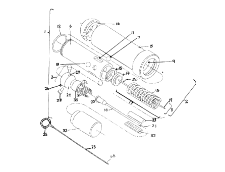
Fig. 1 is an exploded isometric view of the
intraosseous infusion and aspiration apparatus;
CA 0220~623 1997-0~-16
13
Fig. 2A is a perspective view of an infusion device
with the hollow tube, tube connector and bone portal;
Fig. 2B is a perspective view of the bone portal and
S a portion of the attached hollow tube;
Fig. 3A is a side elevation view of the bone portal:
Fig. 3B is a sectional view of Fig. 3A;
Fig. 4 is a perspective view of the assembled
intraosseous infusion and aspiration apparatus;
Fig. 5 is a sectional view of the intraosseous
lS infusion and aspiration apparatus;
Fig. 6 shows the axial displacement of the ball during
release;
Fig. 7 shows the angles on the ball race and the
tapered surface of the bone probe assembly in an example of
an intraosseous infusion and aspiration apparatus;
Fig. 8 shows the forces acting on the ball, inner
sleeve, and outer sleeve during an initial phase of the
release mechanism;
CA 0220~623 1997-0~-16
14
Fig. 9 shows the forces acting on the ball, inner
sleeve, and outer sleeve during a late phase of the release
mechanlsm;
S Fig. 10 is the first stage in the use of the
intraosseous infusion and aspiration apparatus showing the
bone probe against the bone cortical layer and the bone
portal just beginning to penetrate the skin;
Fig. 11 is the second stage in the use of the
intraosseous infusion and aspiration apparatus showing that
the bone portal has penetrated the bone cortical layer;
Fig. 12 is the third stage in the use of the
intraosseous infusion and aspiration apparatus showing that
the inner sleeve has been released from the outer sleeve
leaving the bone portal at the correct depth in the bone
marrow;
Fig. 13 is the fourth stage in the use of the
intraosseous infusion and aspiration apparatus showing that
the apparatus has disengaged from the skin of the patient
and the infusion tube has been left in the patient;
Fig. 14 shows the placement of the template patch on
the patient's sternal bone;
Fig. 15 shows the template patch;
CA 0220~623 1997-0~-16
Fig. 16 shows the placement of the intraosseous
infusion and aspiration apparatus at the target zone of the
template patch;
S Fig. 17 shows the template patch after the
intraosseous infusion and aspiration apparatus has inserted
the bone portal into the bone marrow and has been
disengaged;
Fig. 18 shows the covering for the template patch;
and
Fig. 19 shows an example of a target patch designed
for use at the tibial site for intraosseous infusion.
DETAILED DESCRIPTION WITH REFERENCE TO DRAWINGS
In the following description it is to be understood
that the apparatus has two ends: an operative end that
refers to the bone penetrating end of the apparatus and the
opposite end referred to as the remote end.
The intraosseous infusion and aspiration apparatus 1
serves as an introducer that introduces an object, an
infusion device, to a specific position, a predetermined
depth in the bone marrow. The introducer is comprised of a
pusher, a position sensor, and a coupler that couples the
infusion device to the pusher thus the infusion device is
positioned in the bone marrow through the action of a
CA 0220~623 1997-0~-16
16
pusher, a position sensor that senses the location of the
infusion device that is being positioned, and a coupler
that couples the pusher to the infusion device so that
force exerted on the pusher is transferred to the infusion
S device. The automatic release mechanism of the apparatus
involves all parts except for the infusion device.
A cross-section of the intraosseous infusion and
aspiration apparatus 1 is shown in its preferred embodiment
in Fig. 1. The apparatus has a housing assembly 2, a
plurality of balls 7, a spring assembly 8, a stylet 50,
stylet carrier 48, disc 14 and a bone probe assembly 3.
The housing assembly 2 has an outer sleeve and an
inner sleeve 6. The hollow outer sleeve 5 is cylindrical
in shape and the internal diameter of the cylinder is
slightly larger at the remote end than the operative end.
It serves as the pusher on which force is applied. A ball
race 9 is formed in the interior wall of the operative end
of the hollow outer sleeve 5. The hollow outer sleeve 5
also has a cap 16 with a projection that allows it to fit
snugly on the remote end.
The inner sleeve 6, also of cylindrical shape and
hollow, slidably fits inside the hollow outer sleeve 5.
The inner sleeve 6 has a plurality of ball holes 10
circular in shape and a plurality of elongated pin slots 11
circumferentially spaced about the operative end of the
inner sleeve 6. Preferably, the inner sleeve 6 also has an
CA 0220~623 1997-0~-16
17
annular snap ring 12 that fits on top of the remote end of
the inner sleeve 6. The outer diameter of the annular snap
ring 12 is equal to the inner diameter of the remote end of
the hollow outer sleeve 5 so that the annular snap ring 12
S fits tightly in the hollow outer sleeve 5.
A plurality of balls 7 serve as the coupler coupling
the pusher to the infusion device. The balls couple the
outer sleeve 5 to the inner sleeve 6. The balls 7 are of
a diameter slightly smaller than the ball holes 10 and fit
partly in the ball holes 10 in the inner sleeve 6 and in
the ball race 9 of the hollow outer sleeve 5 coupling the
hollow outer sleeve 5 with the inner sleeve 6.
The spring assembly 8 has a helical spring 13 which
is positioned inside the inner sleeve 6, abutting a disc
14. On one side of the disc 14 abuts a locking ring 15
which snaps into a ring groove in the interior of the inner
sleeve 6 proximate a remote end thereof. On the opposite
side, the disc 14 has a projection that fits snugly into
the remote end of the spring. The locking ring 15 and the
disc 14 couple the compression forces from spring 13 to
the inner sleeve 6.
A stylet 50 is connected with a stylet carrier 48
(see Fig. 5) affixed to the center of the disc 14. Disc
14 is coupled to the inner sleeve 6 and the spring 13.
The force exerted onto the hollow outer sleeve 5 is
transferred to the inner sleeve 6 through the balls 7
CA 0220~623 1997-0~-16
18
coupling the two bodies 5, 6 together and is further
transferred to the spring 13 and stylet 50 through the
locking ring 15 and disc 14. The stylet 50 is rigid and
is inserted into the infusion device 17 to provide support
for the infusion tube 17 and to push the infusion device
17 into the bone.
The infusion device 17 consists of an infusion tube
18, and a bone portal 21. The infusion tube 18 is a
hollow, elongated, flexible tube connected to a tube luer
20 (Fig. 2A) at the remote end. Referring to Fig. 2A and
2B, the infusion tube 18 is connected to the bone portal
21 at its operative end. The infusion tube 18 is glued to
a remote end of the bone portal 21 providing a fluid
passageway from the infusion tube 18 to the bone portal
21. Referring to Figures 2A, 2B, 3A and 3s, the bone
portal 21 is made of a rigid material such as stainless
steel and has a central bore 66 which comml~n;cates with an
opening at its operative end to allow the infusion of fluid
into the bone marrow. On the interior surface of the bore
66 are threads 22. An annular shoulder 60 serves as a
stop for the hollow, flexible infusion tube 18 that is
glued to the exterior surface of the bone portal 21. The
end of the bone portal is beveled to form sharp points 62.
As seen in Fig. 1, the remover 23 has a slender rod
threaded at its end with threads 68 dimensioned to register
with the threads 22 on the interior bore of the bone
portal 21 and a loop 25 at the remote end is used to
CA 0220~623 1997-0~-16
19
remove the infusion tube 18 and bone portal 21 from the
bone marrow after the infusion is complete.
Referring to Fig. 1, the intraosseous infusion and
S aspiration apparatus 1 further includes a bone probe
assembly 3 that serves as a position probe sensing the
location of the object, the infusion device, to be
positioned relative to a reference point. The bone probe
assembly 3 comprises an annular band 26 that is
dimensioned to slide into one end of the inner sleeve 6.
This annular band 26 of the bone probe assembly 3 has a
plurality of pin holes 27. A plurality of pins 28 can be
put through these pin holes 27 and into the elongated pin
slots 11 in the inner sleeve 6 further slidably securing
the bone probe assembly 3 to the inner sleeve 6. The bone
probe assembly 3 also has a conical surface 29 (a ramp in
transverse drawings) adjacent to the annular band 26.
While the annular band 26 is adjacent to the remote end of
the conical surface 29, the bone probe 30 is adjacent to
the operative end. A ring of needles 31 protrude out from
the bone probe 30. There is a protective bone probe
covering 32 that covers the needles 31 to protect an
administrator from accidental contact with the needles 31.
The bone probe needles 31 serve as a reference for
the measurement of the distance through the bone that the
bone portal 21 has penetrated since the needles 31
penetrate the skin and subcutaneous layers overlying the
bone, but do not penetrate the bone.
CA 0220~623 1997-0~-16
The intraosseous infusion and aspiration apparatus 1
further includes longitudinally split support sleeves 33
located between the bone probe 29 and the infusion device
17. Sleeve sections 33 brace the stylet 50 so that it
does not buckle under the force applied to it to penetrate
the bone.
Referring to Fig. 4, the assembled intraosseous
infusion and aspiration apparatus 1 is shown in its
position before use with a protective covering 32 over the
bone probe needles 31.
The intraosseous infusion and aspiration apparatus 1
can be optimized for infusion of different bones such as
the sternum, the proximal and distal ends of the tibia, the
femur, and the clavicle. These bones have different
resistances to penetration thus the amount of force needed
to insert the apparatus in the bone marrow of the bones may
differ. Also, since different depths of penetration of
bone to reach the bone marrow may be needed for different
bones, the bone penetration distance of the bone portal may
need to be adjusted. In addition, the skin and
subcutaneous layers overlying the different bones may
differ in thickness and their resistance to penetration.
The bone probe 30 and spring 13 must be adjusted to
compensate for these changes in the thickness and
resistance of the skin and overlying areas. The
intraosseous infusion and aspiration apparatus 1 may also
CA 0220~623 1997-0~-16
21
be customized for pediatric patients who usually have
smaller bones with lesser resistance to penetration.
One feature of the intraosseous infusion and
aspiration apparatus 1 that can be adjusted is the spring
force applied to the bone probe 30. The bone probe 30
serves as a reference point to determine the depth of
penetration of the bone portal 21 through the bone
cortical layer and bone marrow. The magnitude of the
spring force needed to force the bone probe 30 to
penetrate the skin and subcutaneous layer so that it abuts
the bone cortical layer is dependent on the bone probe
needle 31 configuration, the type of tips of needles 31,
the size and the number of needles 31 in the bone probe
30, and the resistance of the skin and underlying layers.
For example, if the number of needles is decreased than a
weaker spring force may be used for the bone probe needles
31 to penetrate the same skin and underlying tissue. Since
different anatomical sites have different resistances in
the skin and underlying tissues, the spring force and the
bone probe needles 31 can be adjusted to obtain optimum
characteristics for the penetration of the bone probe 30
to the cortical bone.
Another feature of the apparatus 1 that can be
adapted is the release mechanism. Referring to Fig. 5, the
ball release mechanism comprises a plurality of balls 7,
the ball race 9, the ball holes 10, the spring assembly 8
and the conical surface 29 of the bone probe assembly 3
CA 0220~623 1997-0~-16
22
and the bone probe assembly 3 itself. Referring to Fig.
6, the starting position of the ball 7 before release is
on the remote end and the ending position of the ball 7 is
proximate the operative end of the conical surface of the
bone probe 29.
Referring to Fig. 7, the angle of the conical surface
29 on the bone probe assembly 3, the angle of the ball
contacting surface 48 of the ball race 9 and the spring
force can be adjusted to determine the maximum bone portal
penetration force available to insert the infusion device
17 to a predetermined depth. For example, if the angle of
the conical surface with the axis of the bone probe
assembly ~ (see Fig. 6) is increased for a constant ball
race contacting surface angle ~ and constant spring
constant, the maximum available bone portal penetration
force will decrease. If the angle ~ is increased as angle
~ and the spring constant are kept constant, the maximum
available bone portal penetration force will increase. If
the spring constant is increased for constant angle ~ and
angle ~, the maximum available bone portal force will
increase. If this maximum bone portal force is exceeded,
the apparatus 1 is released without damage. Since this
force is much less than the force at which mechanical
failure occurs, the apparatus will not be damaged and the
patient will not be injured.
CA 0220~623 1997-0~-16
23
Fig. 8 shows the forces on the ball release mechanism
in an initial phase where the ball is positioned in the
remote end of the conical surface 29 of the bone probe
assembly 3. In this initial phase, forces up to the
maximum force may be applied without premature release.
Fig. 9 shows the forces on the ball release mechanism as
the balls are positioned in the operative end of the
conical surface 29 of the bone probe assembly 3. In this
late phase, the apparatus 1 may release prematurely since
there is a greater horizontal force acting on the ball 7
forcing the ball 7 onto the ramp 29. The horizontal force
tends to push the bone probe up and causes 30 release. In
this phase, the axial displacement of the bone assembly
lS relative to the inner sleeve 6 is determined by the angle
~, the angle ~ and the diameter of the balls 7. Changing
one of these design variables will change the axial
displacement that occurs in this phase.
Another aspect of the intraosseous infusion and
aspiration apparatus 1 that can be adjusted is the size of
elongated pin slots 11 in the inner sleeve 6 proximate the
operative end. These pin slots 11 determine the maximum
axial displacement of the bone probe assembly 3 in relation
to the inner sleeve 6. Because the infusion device 17 is
coupled to the inner sleeve 6, these pin slots 11 also
determine the maximum penetration depth of the infusion
device 17 in relation to the bone probe needles 31. For
example, if larger penetration depth is required, the pin
CA 0220~623 1997-0~-16
24
slots 11 can be increased in length, resulting in a larger
axial displacement of the bone probe assembly 3 in relation
to the inner sleeve 6 and allowing greater penetration of
the bone marrow by the infusion device 17. In addition, if
there is a failure in the release mechanism, this feature
ensures that the bone portal 21 does not overpenetrate the
bone marrow and cause injury to the patient.
The ball race 9 allows for rotational decoupling
between the hollow outer sleeve 5 and the inner sleeve 6.
Optionally, ball race sections could be provided in order
to provide limited decoupling between the hollow outer
sleeve 5 and the inner sleeve 6. With such a feature, if
the needles 31 were decoupled by use of a bearing on the
bone probe assembly for example, it would be possible to
apply torque to the bone portal 21 in order to assist its
penetration into the bone.
The operation of the intraosseous infusion and
aspiration apparatus 1 and its release mechanism is shown
in Fig. 10, 11, 12, 13. The apparatus 1 contains a
release mechanism for disconnecting the infusion tube 18
and the bone portal 21 from the outer hollow sleeve 5 when
the bone portal 21 is at a specific depth relative to the
outer surface of the cortical bone thereby preventing the
bone portal 21 from penetrating beyond the bone marrow and
out the opposite cortical layer of the bone. Specifically,
the intraosseous infusion and aspiration apparatus 1 is
placed on the target location perpendicular to the skin of
CA 0220~623 1997-0~-16
the patient. A force is applied so that the bone probe
needles 31 go through the skin. A portion of the bone
portal 21 also enters the subcutaneous layer.
S Referring to Fig. 10, the balls 7 are in the ball
holes 10 and ball race 9. The pins 28 sit at the
operative end of the elongated pin slots 11. As more
force is applied on the hollow outer sleeve 5, as seen in
Fig. 11, the inner sleeve 6 moves towards the operative
end of the apparatus 1. Since the infusion device 17 is
coupled through the stylet 50 to the spring 13 which is
coupled to the inner sleeve 6 which in turn is coupled to
the outer sleeve 5, as force is exerted on outer sleeve 5,
the bone portal 21 penetrates the bone cortical layer.
Since the bone probe assembly 3 has not changed in
position, there is relative movement of the pins 28 on the
bone probe assembly 3 towards the remote end of the
elongated pin slots 11 of the inner sleeve 6. The balls 7
coupling the inner sleeve 6 to the hollow outer sleeve 5
are being forced to move out of the ball race 9 of the
hollow outer sleeve 5 and into the ball holes 10 in the
inner sleeve 6 toward the center of the apparatus since the
hollow outer sleeve 5 is moving down relative to the bone
probe assembly 3 and space is created into which the
balls 7 can move.
As seen in Fig. 12, as more force is applied, the
penetration of the infusion device 17 into the bone marrow
to the correct depth takes place. The hollow outer sleeve
CA 0220~623 1997-0~-16
26
5 has been pushed so that the operative end of the hollow
outer sleeve 5 rests on the skin of the patient. The balls
7 have moved out of the ball race 9, through the ball
holes 10, and down the conical surface 29 into the space
between the bone probe assembly 3 and the inner sleeve 6,
uncoupling the hollow outer sleeve 5 from the inner sleeve
6. If more force is applied at this time, the force will
not be transferred from the hollow outer sleeve 5 to the
inner sleeve 6, and the hollow sleeve will travel down
freely until it reaches the skin. In Fig. 13, the hollow
outer sleeve 5 is pulled back, pulling the stylet 50 from
the infusion tube 18. The support sleeves 33 fall out as
the apparatus 1 is removed. The infusion tube 18 can be
connected to another tube 41 or directly to a source of
drugs and fluid using the luer 20 on the infusion tube 18.
This intraosseous infusion and aspiration apparatus 1
can be used in conjunction with a template patch 34. The
template patch 34 is used as a guide to ensure that the
intraosseous infusion and aspiration apparatus 1 is
correctly positioned in the proper location on a bone. A
prominent anatomical feature of the bone like a notch, a
depression, or a bump is used as a reference point to
determine the target location for the infusion or
aspiration of the bone marrow of flat bones such as the
sternum, or iliac crest and long bones such as the femur,
the tibia, or the radius.
CA 0220~623 1997-0~-16
27
Referring to Fig. 14, the template patch 34 includes
a template base 47 which is used to locate a target zone
37 on the manubrium bone of a patient by placing the
finger in peripheral notch 35 and at the same time
locating the finger in the sternal notch 36 of the
patient. Referring to Fig. 15, a target zone 37 in the
template base 47 is positioned a predetermined distance
away from the peripheral notch 35. The target zone 37 is
used to align the intraosseous infusion and aspiration
apparatus 1 with a desired area of penetration of the
patient. Also, the template base 47 has an adhesive
underside with a liner that can be peeled to removably
fasten the template base 47 to the skin of the patient.
In addition, a fastening material 38 is present around the
periphery of the template base 47 so that a covering 44
may be placed on it and engage the fastening material 38.
The template patch 34 also has a tube clamp 39 outside the
fastening material 38 on an extension of the template base
47. The infusion tube 18 may be attached by the tube
clamp 39 to the template patch 34 and then connected to an
intravenous tube through its luer 20. In another
embodiment, a tube 41 with a connector 42 and a connector
43 is glued to the template base 47. Tube 41 is attached
to the luer 20 on the infusion tube 18 with connector 42
and connector 43 is used to attach tube 41 to an
intravenous tube. The tube clamp 39 or the additional tube
41 decrease the strain on the bone portal 21 by creating
the slack in the tube and also prevent the accidental
dislodgment of the infusion tube 18 and the bone portal 21
CA 0220~623 1997-0~-16
28
by either clamping the infusion tube 18 or the additional
tube 41 to the template base 47.
Referring to Fig. 16, the intraosseous infusion and
S aspiration apparatus 1 is placed perpendicular to the
template patch 34 in the target zone 37. After the bone
portal 21 has been inserted into the bone marrow and the
intraosseous infusion and aspiration apparatus 1 removed,
the infusion tube 18 is connected to the glued tube 41
with the infusion tube luer 20 and connector 42 as shown
in Fig. 11. Connector 43 of the tube 41 can be connected
to a source of intravenous drugs or fluid as seen in Fig.
17.
A protective transparent cover 44 can be placed on
the template base 47 after the source of intravenous drugs
or fluid has been connected to the infusion tube 18. Fig.
18 shows a preferred embodiment of the cover 44 which has
a dome 46 of transparent material with fastening material
45 around its periphery. The dome 46 can be placed on the
template base 47 and the fastening material 38 of the
template base 47 can engage with the fastening material of
the cover 44 to protect the site of infusion. The
fastening materials can be hook and loop which allows the
dome to be removed and reattached.
The intraosseous infusion and aspiration apparatus 1
can be used alone if a template patch 34 is not available,
or in conjunction with the template patch 34. The template
CA 0220~623 1997-0~-16
29
patch 34 may also be used with other intraosseous infusion
and aspiration apparatus. When a template patch 34 is
used in conjunction with the intraosseous infusion
apparatus 1, the top half of the backing of the template
S patch 34 is first removed to expose the adhesive lining on
the underside. An appropriate anatomical marker on the
appropriate bone is located, for example the sternal notch
36 in the manubrium bone of the patient. An index finger
is placed on the anatomical marker perpendicular to the
surface of the bone and the peripheral notch 35 on the
template patch 34 is arranged around the finger in the
proper orientation. In this example, the peripheral notch
35 and the target zone 37 are over the patient's midline
on the chest. The top half of the template patch is
lS pressed onto the skin and the rest of the backing is
removed to expose the rest of the adhesive lining that
secures the template patch 34 to the skin of the patient.
The bone probe needles 31 protective covering 32 is
removed. and the bone probe needles 31 are placed on the
target zone 37 with the axis of the apparatus 1
perpendicular to the skin of the patient. The hollow outer
sleeve 5 is pushed into the target zone 37 until the
uncoupling of the hollow outer sleeve 5 from the inner
sleeve 6 is heard and felt. The hollow outer sleeve 5 is
pulled straight back. The support sleeves 33 fall out
leaving the infusion tube 18 and bone portal 21 embedded
in the patient. A syringe is attached to the infusion tube
18 to withdraw marrow to verify that the infusion device
CA 0220~623 1997-0~-16
17 is at the correct depth in the bone. The bone probe
needles protective covering 32 is put back on the
apparatus 1 for safety reasons. The infusion tube 18 is
connected to a second tube 41 glued at the template patch
S 34 through the luer 20 to provide more slack in the tubing
and less strain on the infusion site. The second tube 41
is connected to an intravenous supply of drugs or fluid.
The protective covering 44 is placed on the template patch
34 so as to engage the covering fastening material 45 with
the template patch fastening material 38, protecting the
infusion site from dislodgment. After the infusion is
complete, the infusion tube 18 may be removed by inserting
a remover 23 into the infusion device 17 and turning it
clockwise to engage the threads in the bone portal 21 until
the remover probes turning. The remover is then pulled
straight out removing the infusion tube.
As an example of the specifications of the apparatus 1
used to infuse the manubrium the following represent a
possible design:
Bone probe needles: Ten 18 gauge hypodermic needles
equi-spaced around the bone
probe.
angle ~ = 15 degrees
angle ~ = 60 degrees
Ball radius = 3.16 mm
Maximum force on spring = 20 lbs
Activation distance of
CA 0220~623 l997-0~-l6
31
bone portal relative to end
of bone probe needles = 8.87 mm
Referring to Fig. 19, a target patch designed for use
at the tibial site for intraosseous infusion is shown.
This is a site commonly used in children, and occasionally
used in adult patients. The tibial site target patch has a
feature on it that is aligned with the tibial tuberosity at
the proximal end of the tibia. The patch has a marking on
it for aligning with the ridge of bone that can be felt
along the axis of the tibia. The patch has an adhesive
backing with a liner that is removed to place the patch on
the skin. The patch has a hole in it that is used as a
target for placing any intraosseous needle. This invention
removes the need for judging the distances from the
anatomical landmarks. The patch could also have an
instrument guide that guides the needle into the bone at
the recommended angle of 45 degrees.
The patch could also have velcro (trademark) for attaching
a protective dome designed for placement at this site. The
patch could also have a connector tubing bonded to the
patch to remove stress and strain from the infusion tube.
A similar target patch 34 can easily be envisioned for use
at other target sites, for example the distal end of the
tibia, near the ankle; the distal end of the femur near the
knee; the iliac crest sitei or the distal end of the radius
(lower arm).
CA 0220~623 1997-0~-16
32
While the present invention has been described with
particularity, it should be understood that various
modifications and alterations may be made therein without
departing from the spirit and scope of the invention set
forth in the appended claims.