Note: Descriptions are shown in the official language in which they were submitted.
CA 02205632 1997-OS-16
IMPREGNATED CERAMIC RISER TUBE
AND METHOD OF MANUFACTDRING SAME
Background of the Invention
In metal casting industries, including aluminum
casting, low pressure die casting is frequently performed,
including a technique knawa as "?~ow Pressure Permanent Mold"
(LPPM) processing. As shown in Fig. l, this process uses
what are called riser tubes 10 as a conduit for the molten
metal 4 to pass frown the melt chamber 1 to the mold cavity
2a of mold 2. The mold 2 sits atop the melt chamber and is
fastened to the top of the riser tube 10 which extends
downward into the bath of molten metal 4. Because the
molten metal 4 is forced to rise up the core of the tube,
these tubes are also referred to as "stalks". A sectional
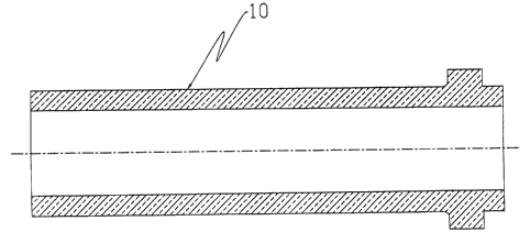
drawing of a typical riser tube is shown in Fig. 2. The
casting operation is achieved by applying a positive gas
pressure, usually 10 to 30 psi., to the surface of the bath
of molten metal. The pressure forces metal into and up the
length of the riser tube and into the mold cavity. The tube
must be nearly gas-tight for two reasons:
1) to prohibit gas from becoming entrained in the
molten metal (caused by the Venturi effect where gas is
siphoned into the tube through the tube wall by the motion
of the molten metal) , resulting in gas voids in the finished
metal casting, and
2) to maintain a positive pressure differential
between the outside of the tube (inside the melt chamber)
and the inside of the tube.
It is this pressure differential that causes the molten
metal to rise up the tube into the mold cavity. Upon
filling the cavity, the molten metal is allowed to solidify
in the mold and form the casting. The pressure is
subsequently released and the molten metal remaining in the
1
CA 02205632 1997-OS-16
stalk is allowed to back-flow out of the tube, draining back
into the melt.
Thus, the desired properties of a riser tube used in
this application include the followings
1) near impermeability to air at application
temperature so that the applied pressure
acts on the aalten metal and does not take
the "path of least resistance" through the
tube;
2) non-reactivity with the molten metal being
cast, to yield high purity metal castings
and to enhance life of the riser tube;
3) controlled thermal conduction and insulation
so that as the metal is cast into the mold
and allowed to solidify, the tube allows the
metal to remain in a molten state which
allows back-flow and drainage of the tube;
and
4) controlled mechanical properties so that as
pressure is applied to the tube/mold cavity
interface to ensure a tight enough seal (to
prevent molten metal leakage) , the tube is
not damaged and can therefore be used again.
Traditional riser tubes are currently formed by
machining metal blanks into the desired geometry, or forming
ceramic tubes (e. g.: silicon nitride, SiAlON, aluminum
titanate, fused silica) using modern conventional processing
techniques. The metal riser tubes that have been
functionally utilized for many years ensure gas
impermeability. These metal tubes can be made of a variety
of materials including basics like iron or steel, or exotics
such as titanium alloys. Iron or steel riser tubes tend to
2
CA 02205632 1997-OS-16
contaminate molten metals such as aluminum via alloying, and
likewise may yield lower quality metal castings. Ia fact,
as an additional maintenance step, many die casting ead-
users coat these iron/steel tubes after each change-out in
an attempt to curtail finished metal casting contamination.
Titanium or other exotic metal alloy tubes may not be
reactive with molten aluminum, but are quite expensive.
Fused silica ceramic riser tubes are frequently used,
but lack mechanical strength to survive typical handling
techniques in a casting facility. In the case of molten
aluminum, silica is reactive with this metal, and hence, the
molten metal may pick-up contamination and the life of the
tube is shortened. Also, these fused silica tubes are
typically gas permeable thus providing sub-optimal stalk
performance and metal casting quality. The currently used
more exotic ceramic riser tubes such as silicon nitride,
SiAlON, and aluminum titanate are generally inherently
nearly gas impermeable, but are also expensive due to high
raw material and processing costs.
Typically, low pressure die casta.ag systems are
utilized a high proportion of available time, and thus
require regular maintenance and monitoring. Commonly, at
some time interval (or number of cycles interval), riser
tubes are removed from the die casting apparatus, allowed to
cool, cleaned (molten metal peeled off), aad then are
reinstalled. Ia some cases, includiag with fused silica
ceramic and iron/steel metal, they are also sometimes coated
in some meaner before reinstallation. Frequent handling of
this nature necessitates a riser tube material with a
reasonable degree of mechanical strength. Exotic alloys and
composites provide adequate thermal properties but lack the
mechanical strength to survive simple mishandling such as an
accidental minor hit against a building wall, etc.
3
CA 02205632 2001-03-12
Thus, consideration was given to utilize a riser tube
material of appropriate thermal conductivity to maintain the
metal is a molten state, sad also to have reasoa;able
mechanical properties to survive the necessary rigors of
normal industrial use. There are some ceramic materials
that csa fulfill those requirements. However, there are ao
knows economical ceramic materials that are also nearly gas
impermeable, which is a key characteristic is this
application, as has been explained.
Summary of the Invention
Briefly stated, according to t:he present invention, a
porous ceramic tube substrate is first formed or obtained,
followed by treatment with a specially developed
impregnation method to provide a novel ceramic riser tube
that is nearly gas impermeable. This tube is used as a
stalk in low pressure die casting equipment for the casting
of aluminum and other metal components.
According to the present invention, the ceramic riser
tube is a better insulator (lower thermal conductivity) than
a metal riser tube, so the molten metal remains hotter
within the ceramic tube resulting is less likelihood of a
"freeze-up" (metal solidification) is the tube, and enabling
back-flow drainage of the molten metal from the tube back to
the furnace melt. The lower cost of an impregnated ceramic
riser tube is an advantage compared to more costly silicon
nitride, SiAlON, and aluminum titaaate ceramic riser tubes,
as well as non-reactive high temperature capability metal
alloy riser tubes.
Various ceramic forming methods can be used to make the
porous ceramic tube substrate, including the freeze-casting
method described is U.S. Patent 4,246,209.
According to this method,
4
CA 02205632 1997-OS-16
aqueous slurries containing inorganic colloidal sol and
inorganic ceramic particles are injected or cast into a
single mold, frozen, and then demolded to form a ceramic
component, in this case, a porous ceramic substrate tube.
This tube is then dried and fired using standard methods.
The porous ceramic substrate tube can be made of a
variety of ceramic co~positions, including but not limited
to: alumina, mullite, cordierite, silicon carbide, silica,
silicon nitride, aluminum nitride, magnesia, alumina-
magnesia spinal, aluminum titanate, zircon, zircoaia, clays,
and any combinations thereof.
The ceramic tube substrate is then further processed
with an impregnation method according to the present
invention to make the tube nearly gas impermeable. In this
method, the ceramic tube is first immersed into a pressure
tight vessel containing inorganic colloidal sol or inorganic
particle suspension, then vacuum is applied followed by a
gas pressure application. Following the impregnation, the
tube is they dried and fired again.
The final tube structure has significantly reduced
surface porosity is air at room temperature and virtually no
interconnected pores on the surface at application
temperature (1300-1500°F). The present method can be used
with freeze-cast formed ceramics or any other ceramic, as
long as the pore sizes of the substrate are larger than the
particle sizes of the solids in the inorganic colloidal sol
or inorganic particle suspension impregnant. Because this
impregnation method can be used with a variety of different
ceramic substrate materials, it provides the flexibility to
produce finished impregnated ceramic tubes that have the
specific ceramic properties desirable for the application
and end-user.
5
CA 02205632 1997-OS-16
Brief Description of the Drawings
Fig. 1 is a cross-sectional view of a low pressure die
casting apparatus;
Fig. 2 is a cross-sectional view showing the contour of
a riser tube according to the present invention;
Fig. 3 illustrates an apparatus for impregnating a
porous riser tube according to the present invention; gad
Fig. 4 illustrates a partial cross-sectional view
showing the relative degree of impregnation according to the
present invention.
Detailed Descrivtion of Preferred Embodiments
The scope of the invention is further described in
connection with the following examples which are set forth
for purposes of illustration only and are not to be
construed as limiting the scope of the invention in any
matter.
A single procedure was followed for each tube
manufactured. First, a ceramic riser tube substrate was
processed using the method of U.S. Patent 4,246,209.
Following forming, each tube was dried at temperature of
around 200°F for about 4 to 8 hours, although this specific
drying temperature and schedule is not critical.
Subsequently, each tube was fired to the temperature
prescribed for that specific ceramic material. It is noted
that the pore size distributions of the different fired
ceramic tube substrates were approximately the same, as was
the appearance of the surface of the tubes. Each ceramic
substrate tube formed had a nominal median pore size of
approximately 5 microns. It should be noted that, in order
to make tubes that are resistant to reaction with molten
aluminum, a non-wetting agent (as known in the art such as
commercially available barium sulfate) was included as part
6
CA 02205632 1997-OS-16
of the ceramic tube substrate raw material batch prior to
forming.
Following the forming and firing of the ceramic
substrate tubes, each ceramic tube 10 was then in~ersed in
a bath of imgregaation media 30 in as air-tight pressure
chamber 20, as shown is Fig. 3. after sealing the chamber
20, chamber 20 was evacuated by application of a vacuum
through vacuum fitting 21. The vacuum was held to evacuate
as much of the air as possible from the pore network of the
substrate. Upon sufficient evacuation, air pressure was
applied through pressure fitting 22 to the liquid (and
substrate) for a specific time period to force the
impregnation media (liquid and particle) into the
substrate's pores. The wet impregnated tube was removed
from the chamber, dried in air at room temperature, and re-
fired as prescribed earlier.
The final structure of the impregnated tube is believed
to correspond with the partial cross-section shown in Fig.
4, although no SEM analysis was done to provide a precise
illustration. As shown, the riser tube 10 is made up of
ceramic particles 11 of various sizes. The particles are
three-dimensionally bonded together and define a three-
dimensional porous structure. The outer pores 12 are
plugged or substantially sealed by ceramic impregnation
material 13 provided by firing of the impregnation media 30.
It is estimated that the ceramic impregnant material
penetrated the tube 10 on the order of 0.1 to 1.0 mm in
depth. The present invention.thus provides a substantially
impermeable riser tube that can support an inside/outside
pressure differential over a minimum time period as
described hereinbelow.
The impregnated tube was then subjected to a pressure-
drop test at room temperature to determine the level of
7
CA 02205632 1997-OS-16
impermeability to gas. In the test, the tube is sealed at
both ends (using a clamping device and rubber gaskets), with
as air intake fitting installed to one of these ends such
that as air lice can be attached to it. Regulated low
pressure air is pumped into the sealed tube through the air
fitting, such that the tube is pressurized to 6 psi. After
this 6 psi pressurization, the air intake line to the sealed
tube is shut-off and the pressure is allowed to drop to 3
psi. The time for this pressure reduction (from 6 psi to 3
psi) determines the acceptability of the tube. Based on
input from an end-user of riser tubes (e. g., an aluminum
low-pressure die caster) regarding one particular riser tube
design. a minimum time is seconds was designated (which
varies for each material composition and riser tube
configuration) for this pressure reduction to occur. This
is done as a means to determine whether the tube would work
successfully in application. Tubes that take longer than
the specified minimum time to drop from 6 psi to 3 psi of
air pressure were deemed better (less gas permeable) than
those that took less than the specified minimum time (more
gas permeable).
Further, because of the pore network of the substrates
formed using the present process. a particular impregnation
media was used. A colloidal silica sol~ an aqueous
dispersion of approximately 30% concentration of 7
nanometers nominal average size silica particles was
utilized. The freeze-cast ceramic tube substrate would
easily accept particles of this size into the nominal median
5 micron size pores.
It was found that although prior art fused silica riser
tubes reacted with molten aluminum the embodiments herein
did not appear to do so. It is believed that the pore
network structure of the substrate together with the non-
8
CA 02205632 1997-OS-16
wetting agent protected the otherwise reactive silica from
the molten aluminum. lPhile the ceramic substrate tubes used
is the examples in this invention were formed by the freeze-
casting method, porous ceramic substrates formed by other
processes and made of other compositions than those
mentioned herein would also perform satisfactorily.
Further, while inorganic silica sol was used in this case,
other types of inorganic colloidal sots and inorganic
particulate suspensions would also work satisfactorily in
the present invention. It is particularly important in the
present invention, however, that the solids in the sol or
suspension have an average particle size that is lower than
the ceramic substrate's average pore size.
Example 1 - Impregnation of Ceramic Substrate Tube of
Alumina/Silicon Carbide Composite
A ceramic tube substrate was formed using the freeze-casting
method of U.S. Patent 4,246,209 and fired. The composition
of the ceramic tube substrate in this example was nominally
as follows:
82% alumina
9% silicon carbide
4% silica
5% aluminum non-wetting agent
and traces of other components
The approximate outside dimensions of this formed tube were
7.8" long x 3.3~ outside diameter (with wall thickaesses
ranging from 0.5" to 1" along the length of the tube). The
ceramic tube substrate was immaersed in a bath of silica sol
and evacuated to 25 inches Hg for a period of 5 minutes .
After shutting off the evacuation, pressure was applied
using compressed air to a level of 150 psi for a period of
5 minutes. After shutting off the pressure and venting the
9
CA 02205632 1997-OS-16
chamber, the tube was removed, allowed to air dry at room
temperature for 16 hours or longer, and fired to the usual
prescribed temperature of 1832°F with a 1 hour hold. The
cross-section of a fired, sliced impregnated ceramic riser
tube microscopically showed that the impregnaat penetrated
and plugged surface pores of the ceramic substrate.
The ceramic tube substrate before impregnation had as
apparent porosity of 15-20%. which was a factor in
permitting impregnation to occur. The ceramic substrate
before impregnation had a room temperature flexural strength
(3 point modulus of rupture) of 4,300 psi nominally, and
this was virtually unaffected by impregnation. The weight
of an unimpregaated fired tube substrate was 3096.12 gm,
and, after impregnation, drying and refiring, increased to
3173.41 gm (+77.29 g): a weight gain of 2.50%. Upon
pressure testing of this impregnated riser tube, 13.3
seconds time was required to relieve the tube from 6 psi to
3 psi pressure, thereby providing acceptable results.
Repeating the impregnation, drying, and refiring steps a
second time resulted is further increases is weight gain and
pressure loss time. Other impregnated tubes were
subsequently processed in the same manner, with the same
com:positioa, etc., and the pressure testing relief times
ranged from 9 to 15 seconds: all acceptable based upon the
8 second minimum time specified by an end-user in the
aluminum die casting industry.
Example 2 - Impregnation of Ceramic Substrate Tube of
Alumina/Silicon Carbide Composite
A ceramic tube substrate was formed using the freeze-casting
method of U.S. Patent 4,246,209 and fired. The composition
of the ceramic tube substrate in this example was nominally
as follows:
CA 02205632 1997-OS-16
82% alumina
9% silicon carbide
4% silica
5% aluminum non-wetting agent
and traces of other coaaponents
The approximate outside dimensions of this formed tube were
7.8~ long x 3.3~ outside diameter (with wall thicknesses
ranging from 0.5~ to 1~ along the length of the tube). The
ceramic tube substrate was immersed in a bath of silica sol
and evacuated to 20 inches Hg for a period of 20 minutes.
After shutting off the evacuation, pressure was applied
using compressed air to a level of 100 psi for a period of
minutes. After shutting off the pressure and venting the
chamber, the tube was removed, allowed to air dry at room
15 temperature for 16 hours or longer, and fired to the usual
prescribed temperature of 1832°F with a 1 hour hold. The
cross-section of a fired, sliced impregnated ceramic riser
tube microscopically showed that the impregnant penetrated
and plugged surface pores of the ceramic substrate. The
20 cersmic tube substrate before impregnation had an apparent
porosity of 15-20%, which was a factor in permitting
impregnation to occur. The ceramic substrate before
impregnation had a room temperature flexural strength (3
point m;odulus of rupture) of 4,300 psi nominally, and this
was virtually unaffected by impregnation.
The following data were measured from five samples made
in accordance with the process of Example 2 discussed above .
~regnated Tube Impregnated Tube
Avg. Pressure Drop5.75 sec (0.23) 13.38 sec (1.01)
(st. dev.)
3 0 Avg. Weight (st. 3069.70 gm (10.54) 3152.28 (9.80)
dev.)
11
CA 02205632 1997-OS-16
As shown above, the pressure drop time increased
significantly, ~rell above the 8 sec minimum specified by the
end user for these particular samples. In addition, the
samples increased in weight by about 2.7%.
The samples were they impregnated a second time wader
the same conditions noted above. The samples were found to
have an average weight of 3199 gm (st. dev. 11.24) and an
average pressure drop of 19.75 sec (st. dev. 1.15). Thus,
it is quite clear that additional impregnation steps can
further increase impermeability
Example 3 - Impregnation of Ceramic Substrate Tube
of Fused Silica
A ceramic tube substrate was formed using the freeze-casting
technology described in U. S. Patent 4, 246, 209 and fired. The
composition of the ceramic tube substrate in this example
was nominally as follows:
86.5% silica
8.5% alumiaa
5% aluminum non-wetting agent
and traces of other components
The approximate outside dimensions of this formed tube were
7.8" long x 3.3" outside diameter (with wall thicknesses
ranging from 0.5" to 1" along the length of the tube). The
ceramic tube substrate was iamaersed in a bath of silica sol
and evacuated to 20 caches Hg for a period of 20 minutes.
After shutting off the evacuation, pressure was applied
using compressed air to a level of 100 psi for a period of
20 minutes. After shutting off the pressure and venting the
chamber, the tube was removed, allowed to air dry at room
temperature for 16 hours or longer, and fired to the usual
prescribed temperature of 1832°F with a 1 hour hold. The
cross-section of a fired, sliced impregnated ceramic riser
12
CA 02205632 1997-OS-16
tube microscopically showed that the impregnant penetrated
and plugged surface pores of the ceramic substrate.
The ceramic tube substrate before impregnation had
apparent porosity of 24-28%. which was a factor in
permitting impregnation to occur. The ceramic substrate
before impregnation had a room temperature flexural strength
(3 point modulus of rupture) of 1,700 psi nominally, and
this was virtually unaffected by impregnation. The weight
of an unimpregnated fired tube substrate was 1870.64 gm,
and, after impregnation, drying and refiring, increased to
1956.28 gm (+85.64 g): a weight gain of 4.58%. Upon
pressure testing of the impregnated riser tube, 4.0 seconds
time was required to relieve the tube from 6 psi to 3 psi,
thereby providing acceptable results. Three seconds was
established as the minimum for this composition and tube
configuration, based upon specifications and feedback from
an end-user of such riser tubes.
While preferred embodiments have been described herein
in particular detail, modifications thereto may be made
without departing from the spirit of the present invention
and still fall within the scope of the present claims.
13