Note: Descriptions are shown in the official language in which they were submitted.
CA 02205681 1997-OS-16
THERMAL SPRAY GUN WITH INNER PASSAGE LINER
AND COMPONENT FOR SUCH GUN
This invention relates to thermal spray guns, and particularly to
the passage for the spray stream in such a gun.
BACKGROUND
Thermal spraying, also known as flame spraying, involves the heat
softening of a heat fusible material such as metal or ceramic,
and propelling the softened material in particulate form against
a surface which is to be coated. The heated particles strike the
surface where they are quenched and bonded thereto. In one type
of thermal spray gun, the heat fusible material is supplied to
the gun in powder form. Such powders are typically comprised of
small particles, e.g., between 100 mesh U.S. Standard screen size
(149 microns) and about 2 microns. The carrier gas, which
entrains and transports the powder, can be one of the combustion
gases or an inert gas such as nitrogen, or it can be simply
compressed air. Other thermal spray guns utilize wire as a
source of spray material.
Especially high quality coatings of thermal spray materials may
be produced by spray guns using oxygen and fuel at very high
velocity (HVOF guns). This type of gun has an internal
combustion chamber with a high pressure combustion effluent
directed into the constricted throat of a short or long gas cap
(also sometimes termed nozzle). Powder is fed axially or
radially into the combustion chamber or gas cap to be heated and
propelled by the combustion effluent to a workpiece being coated.
Examples of HVOF guns are disclosed in U.S. Patent Nos. 4,417,421
(Browning) and 5,148,986 (Rusch). Generally the powder (or wire)
spray material in HVOF guns is introduced internally into a spray
34 passage where there can be a tendency to deposit on the passage
walls with resulting buildup. The buildup can dislodge to pass
1
CA 02205681 1997-OS-16
lumps onto the coating, or close down the passage to result in
backpressure and attendant malfunction of the gun. U.S. patent
No. 5,165,705 (Huhne) addresses such deposit by the application
of a surface film in the combustion chamber. Reflective surface
films have been taught for a different purpose, vis. enhancement
of heating, in U.S, patent No. 3,055,591 (Shepard). A ceramic
flow nozzle is taught in U.S. patent No. 5,405,085 (White),
wherein the ceramic nozzle absorbs heat from a first portion of
flow stream, and transfers the heat to a second portion of the
flow stream downstream.
An object of the invention is to provide an improved thermal
spray gun, particularly an HVOF gun, having a reduced tendency
for buildup in the spray stream passage in the gun. Another
object is to provide a novel component for such a gun, such
component providing for a reduced tendency for buildup in the
spray stream passage in the gun.
BRIEF DESCRIPTION OF THE DRAWING
The drawing illustrates a longitudinal section of a portion of a
thermal spray gun incorporating the invention.
2 0 SUN~iARY
The foregoing and other objects are achieved, at least in part,
in a thermal spray gun that includes a combustion chamber, gas
means for injecting a fuel gas and a combustion-support gas into
the combustion chamber, a gas cap with a passage extending from
the combustion chamber to an exit end, and feeding means for
feeding a thermal spray material into the passage. The gas cap
comprises a tubular inner member forming at least a substantial
portion of the passage, and cooling means for cooling the inner
member. Preferably the cooling means comprises liquid means for
flowing liquid coolant in the gas cap in thermal communication
with the inner member. The inner member is formed of a thermally
conductive material with a hardness of at least Rc65, preferably
2
CA 02205681 1997-OS-16
a carbide in a metal matrix, such as tungsten carbide in a cobalt
matrix. With combustion of the fuel gas in the combustion
chamber, a spray stream containing the thermal spray material in
finely divided form is propelled through the exit end without
substantial buildup of thermal spray material in the passage.
In a preferred aspect, the gas cap further comprises a nozzle
component formed of the inner member and a metallic outer member.
The inner member is affixed within the outer member in thermal
contact therewith, and the outer member is in direct contact with
the flowing fluid coolant. Copper or copper alloy is
particularly suitable for the outer member.
Objects are also achieved by a nozzle component for such a gun.
The component comprises an inner member formed of a thermally
conductive material with a hardness of at least Rc65, preferably
a carbide with a metal matrix. The nozzle component has a
central passage therethrough with the inner member forming at
least a substantial portion of the central passage of the gas cap
of the gun. The nozzle component is configured for insertion as
a component of the gas cap for the passage to extend from the
combustion chamber to an exit end so as to pass the spray stream
therethrough, such that the inner member is in thermal
communication with the liquid coolant.
DETAILED DESCRIPTION
One type of thermal spray gun incorporating the invention is
similar to that described in the aforementioned U.S. patent No.
5,148,986. The gun is modified as set forth herein. With
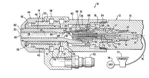
reference to the drawing, a thermal spray gun 10 includes a
cylindrical gas body 12 with a gas cap 14 mounted thereon. Fuel
gas from a pressurized fuel source is obtained through a
conventional valve portion of the gun (not shown), and a
combustion support gas is obtained from a pressurized source such
as compressed air or preferably oxygen. Additional air, such as
for an annular flow in the gas cap, is optional but not necessary
3
CA 02205681 1997-OS-16
in the present embodiment.
The gas body 12 includes a support member 13. The nozzle member
16, an intermediate member 18 and a rear member 20 held together
coaxially in the member 13 with a nozzle nut 24. The nozzle
member extends into the gas cap 14 which, together with the
nozzle member forms a combustion chamber 26. The gas cap has a
central passage 28 extending from the chamber to an exit end 30.
Advantageously with the present invention, the gas cap and its
passage are elongated, so that the passage generally has a ratio
of length to minimum diameter of between about 5 and 25.
Rearward of the passage, a forwardly converging portion 32
proximate the nozzle 16 extends to a constriction 34 to thereby
form the combustion chamber. The forward convergence 32 of the
gas cap from the nozzle is at an angle preferably between about
5° and 15°, e.g. 12° with the central axis 35 of the gun.
The
elongation of the gas cap passage 28 provides for an extended
heating and accelerating zone for a thermal spray powder. (As
used herein and in the claims, "forward" or "forwardly" denotes
toward the exit end of the gun; and "rear", "rearward" or
"rearwardly" denotes the opposite. Also "inner" denotes toward
the axis, and "outer" denotes away from the axis.)
The gas cap 14 is an assembly that includes a tubular nozzle
component 38 retained within a cylindrical outer body 40 with
channelling 42 therebetween for water or other fluid, preferably
liquid, for cooling. A forward retainer 44 with threading 45
holds a cylindrical baffle 46 in the outer body to effect
directed channeling. A fluid transfer block 48 surrounds part of
the outer body. This block has a fluid inlet 50 and butlet (not
shown), and a connecting pair of annular channels 49 formed
cooperatively with the outer body which also has a connecting
pair of radial ducts 51 therein, all connected for supporting
flow-through of the water in the channelling. Appropriate O-
rings 52 seal the channeling. The outer body is attached to the
gas body 12 with threading 54 and retains the component 38 by a
4
CA 02205681 1997-OS-16
shoulder 53 thereon.
The intermediate member 18 is retained in a corresponding bore in
the support member 13. The intermediate member and associated
components are fitted with a plurality of O-rings 56 to maintain
gas-tight seals. The member 18 has therein a first annular
groove 53 associated with at least one (e. g. 8) arcuately spaced
longitudinal passages 55 (one shown) directed forwardly
therefrom. The intermediate member 18 also has a second annular
groove 57 forward of the first groove 53. At least one (e.g. 8)
further arcuately spaced longitudinal passages 58 (one shown) are
directed forwardly from the second groove, spaced arcuately with
and outwardly from the first passages 55. The two sets of
passages 55, 58 lead t9 respective annular spaces 60, 62 in the
rear section of the nozzle member 16.
A plurality of arcuately spaced tubes 64 (e. g. 8 tubes) are press
fitted into the nozzle member 16 so as to converge forwardly from
the one annular space 62. A similar plurality of drilled holes
66 from the other space 60 are alternated arcuately with the
tubes. The tubes convey fuel,.and the holes convey oxygen to an
annular mixing region 68 near the face 69 of the nozzle. The
fuel mixture is injected from this region into the chamber 26
where combustion takes place, effecting a high pressure, high
velocity flow of combustion product through the central passage
28.
The foregoing example illustrates one means for introducing the
fuel and oxygen into the chamber. The actual means is not
critical to this invention and may be conventional or otherwise
desired. For example, the gas channels may be formed as a pair
of concentric annular gas passages. In other embodiment, the
fuel and oxygen gases may be mixed further back in the gas body
in a siphon plug or the like. Alternatively, each gas may be
introduced directly into the chamber without initial mixing.
A tube 72 with a central channel 73 for a thermal spray powder
5
CA 02205681 1997-OS-16
extends from the rear member 20 into and through the nozzle 16 to
the combustion chamber. The central channel is fitted into an
axial channel 74 in the rear member 20 which in turn connects
with a further channel 75 in the support member 13. The latter
channel, in turn, communicates with a hose 76 from a powder
feeder 77 (by way of conventional gun fittings). Powder from the
feeder is entrained in a carrier gas from a pressurized gas
source 78 such as compressed air or nitrogen. The powder feeder
is a conventional or desired type but must be capable of
l0 delivering the carrier gas at high enough pressure to deliver
powder through the powder channels into the combustion chamber
26.
Supplies of the gases to the combustion chamber should be
provided at a high pressure, preferably at least five atmospheres
of pressure, for high velocity operation. The combustible
mixture is ignited in the chamber conventionally such as with a
spark device, so that the mixture of combusted gases will issue
from the exit end as a sonic or supersonic flow entraining the
powder. The heat of the combustion will heat soften or melt the
powder material, or at least propel it at sufficient velocity, to
deposit a coating onto a substrate.
According to the present invention, the nozzle component 38 of
the gas cap 14 includes an inner member 80 formed of a thermally
conductive material having a hardness of at least Rc65.
Preferably this material is a carbide in a metal~matrix so as to
provide both high hardness and thermal conductivity. The carbide
itself is preferably tungsten carbide, chromium carbide, boron
carbide, titanium carbide or silicon carbide. The matrix metal
should be at least 3% by weight of the total of the carbide and
the matrix, and preferably is a heat resistant metal,
advantageously nickel or cobalt neat or as an alloy thereof, for
example with 20% by weight chromium in the nickel, such alloying
being to improve heat resistance or other properties. Tungsten
carbide bonded with a cobalt matrix is particularly suitable.
The tungsten carbide may be sintered or cast tool grade carbide
6
CA 02205681 1997-OS-16
containing cobalt in a range of about 3% to 20% by weight, for
example 6% cobalt. Other suitable carbides and matrix metals for
the purpose are tungsten carbide in a nickel matrix, chromium
carbide in a nickel chromium alloy matrix, boron carbide in a
nickel matrix, titanium carbide in a nickel matrix, and silicon
carbide in a nickel matrix.
The term "thermally conductive" is intended to mean reasonably
conductive, not necessarily as good as some metals, but
distinguished from thermally insulating. The ultimate function
of the liner being thermally conductive is to remove heat away
from the liner sufficiently well for it to remain relatively
cool, preferably less than 260°C (500°F) .
In a preferred embodiment the nozzle component 38 further
includes a metallic, tubular outer member 82. The inner member
80, of a hard, thermally conductive material as set forth above,
is affixed as a liner within the outer member in thermal contact
therewith. The outside surface of the outer member is in direct
contact with the flowing water or other fluid coolant in the
channelling 42. The liner 80 is in the form of an insert of
carbide or the like, at least 0.75 mm thick and generally up to
about 8 mm, e.g. 1.6 mm thick. The liner is press fitted, brazed
or the like, into the outer member. Alternatively, the outer
member may be cast onto the liner. The liner 80 should be in
intimate contact with the outer member 82 for thermal conduction
of heat generated by the combustion and carried by the spray
stream through the passage. The outer member should be a good
thermal conductor, preferably being copper, brass or other high
copper alloy. In the present configuration, the rear end 32 of
the outer member forms an initial converging portion of the
passage to delimit the combustion chamber. A straight portion 84
of passage in the outer member extends from the chamber before
the carbide insert forms the remaining portion of the passage.
The insert should extend the passage smoothly without creating a
significant edge to disrupt flow. The liner, although not
7
i i
CA 02205681 2002-05-29
necessarily extending the full length of the passage, should be located at
least where there is a
tendency for any buildup of spray material, and may extend back into the
combustion chamber.
The present arrangement allows a nozzle component 38 comprising an inner
member in
accordance with the invention to replace a worn or otherwise deteriorated
component in a
thermal spray gun. Such a component also may substitute for a prior component
in a thermal
spray gun such as a type shown in the aforementioned U.S. patent No.
5,148,986.
Other configurations may be used. For example, the passage 28 may expand
toward the outer
end to enhance development of supersonic flow, as shown in the aforementioned
U.S. patent No.
4,416,421. In another example, the inner member 80 may constitute the nozzle
component in the
form of a self supporting member in direct contact with the cooling fluid,
without an outer
member. Although particularly directed to an elongated gas cap and passage, an
inner member
with cooling thereof may be utilized in a shorter gas cap, for example of the
type disclosed in the
aforementioned U.S. patent No. 5,148,986 with respect to FIG. 4 thereof. A
short gas cap may be
formed substantially only of an outer member and an inner member, wherein the
outer surface
exposure to air constitutes a cooling means to provide sufficient cooling. In
another
embodiment the liquid cooling may be replaced with a plurality of fins
extending outwardly from
an outer member into the ambient air, or into a flow of cooling or shroud air
used with the spray
process, so as to allow air cooling.
The spray material generally is introduced in any conventional or desired
manner compatible
with the invention. Powder may be fed axially, as shown or with the tube 73
extending farther
into the chamber 26 or into the passage 28. Alternatively, the powder may be
injected through a
ring of orifices (not shown) proximate the axis 35 of the gun. In another
alternative, the spray
material may be fed radially into the passage in the conventional manner.
8
OTTAWA214176.1 200205221555
CA 02205681 1997-OS-16
Although the invention has been described for a powder thermal
spray material, it may be utilized with a gun that sprays from a
wire form of the material, particulaly using a short form of air
cap.
In the present example the inner end of the gas cap forms the
combustion chamber cooperatively with the face of the nozzle that
injects the combustion gases. In other cases the invention may
be associated with a combustion chamber that is in a gun body
separate from the gas cap, as in the type of gun taught in the
aforementioned U.S. patent No. 4,416,421. In that case the
passage for the spray stream includes an orthogonal portion
connecting into the combustion chamber, and the hard inner member
would be in the portion of the nozzle after the orthogonal
portion.
It has been found that thermal spray gun with an elongated gas
cap according to the invention can be operated for an extended
period of time spraying aluminum oxide, nickel alloy with 25%
chromium, nickel-chromium-boron-silicon self-fluxing alloy and
chromium carbide in nickel-chromium alloy binder. Such spraying
has been effected without substantial buildup of thermal spray
material in the passage. This demonstrated a significant
improvement over similar guns without such a liner, and over such
guns with a chrome plate coating in the central passage.
While the invention has been described above in detail with
reference to specific embodiments, various changes and
modifications which fall within the spirit of the invention and
scope of the appended claims will become apparent to those
skilled in this art. Therefore, the invention is intended only
to be limited by the appended claims or their equivalents.
9