Note: Descriptions are shown in the official language in which they were submitted.
CA 0220~719 1997-0~-20
C162.01/I
rltle: Hin~ed Closure
Field of the Invention
This invention concerns improvements in mech~ni~mc for assisting the lifting of hinged
closures, in particular car boot lids, tailgates and car bonnets.
Background of the Invention
It is becoming increasingly a requirement in the motor industry Iha~ car boot lids (i.e. the
trunk or rear lid) should need little or no manual effort to be opened, especially starting
from the closed position. For example, a person wishing to load luggage or shopping into
the boot of a car often has only one hand free, so that the lid has to bc unlocked and lifted
single handed. This can present a real problem for elderly or infirm pcrsons.
Boot lids for saloon cars, as distinct from the tailgates of so-called hatch-backs, are
commonly hinged about a single pivotal axis by means of a so-called swan-neck bracket
mounted one on each side of the lid, with springs controlling the weight of the lid. This
enables the lid to move clear of the adjacent edge of the body. However this design has
the disadvantage that the boot capacity is reduced by the swan-neck brackets, and therc
is a risk that the intruding brackets may damage high level luggage or othcr contents of
the boot.
To avoid this problem, it has become conventional for boot lids to be pivoted about a pair
Or multi-link multi-axcs hingcs. Whcn ~hc lid is closcd lhC hin~cs collal-sc lo I crmit ~hcir
stowage in the shallow gutters on each side of the boot, between ~he boot seals and the
outer body. Assistance in opening the lid is commonly provided by a gas strut acting on
each hinge, and since it is undesirable for the struts to intrude into the boot space, it is
necessary for them also to be located in the side gu~ters. Clcarly, such an almos~
CA 0220~719 1997-0~-20
horizontal attitude of the struts has conventionally resulted in them providing a poor
mechanical advantage, so that the struts can give litlle assislance cluring the initial opening
of the lid, where the maximum ~c~ict~nce is called for.
It is therefore an object of the invention to provide an improved mechanism for lifting
closures such as engine compartments and boot lids.
Summary of the Invention
According to one aspect of the present invention there is provided a hinge mechanism for
ting the lifting of a closure hinged to a body (typically a boot lid or tailgate hinged
to a motor vehicle body) comprising: a hinge device permining pivoting of the closure
about the body, and a compressible strut acting between a hinge part attachable to the
body and a hinge part attachable to the closure; wherein one cnd of the strul acts through
a pivotable thrust member whose movement is constrained, at least then the two hinge
parts are in close proximity (as when the closure is in a lowered position), by engagement
of a part thereof with plate means, so as during initial opening Or ~he closure to enable
pivoting movement of the thrust member, due to the force of the strut, to cause a lifting
movement of the closure.
The plate means may be a straight plate, which is preferably inclined.
Advantageously, however, the plate means is constituted by a cam having a concave cam
surface.
The thrust member may comprise a lever pivoted near its centre to a hinged part, one end
of the lever carrying a roller engageable with the cam surface, while its other end is
pivotally connected to one end of the strut.
In a preferred arrangement the cam is mounted on the hinge part which is a~tachable to
the body, and the thrust member is mounted on the hinge part which is at~achable to the
closure.
CA 0220~719 1997-0~-20
Stop means is preferably provided to limit rotational movement of the thrust member, so
that during lowering of the closure the cam eng~ging part thereof is correctly positioned
for engagement with the cam surface.
The compressible strut is preferably a gas strut.
In a preferred arrangement two such hinge mech~ni.cm.c are provided, one on each side of
the closure, such as a bonnet or a boot lid. In particular, the hinge device may be a four-
link hinge.
Advantageously the body side hinge part is elongated so that one end of the strut may be
pivotally joined to that hinge part, albeit remote from the cam surface.
Preferably the characteristics of the strut, the geometry of the cam and cam follower and
the action of the thrust member are selected and arranged such that a positive opening
force is applied to the lid throughout its entire opening movement.
Although the mechanism is particularly suited to a car boot lid, it may be equally applied
to a bonnet (engine compartment closure/lid) of a motor car. Furthermore, the mechanism
may be used in other applications outside the motor industry, wherever assistance in lifting
a heavy closure is required.
The invention also resides in a hinge mechanism when fitted ~o a closure and body, eg of
a car.
According to another aspect of the invention a lifting aid comprises a compressible strut
for ~tt~chment between a closure and a body towards and away from which the closure
is pivotally moveable, wherein one end of the strut is adapted to be pivotally attached
directly to the body and the other end is pivotally attached to a thrust member which itself
is pivotally attachable to the closure, and ramp means is attachable to the body at a
position such that the thrust member engages the ramp means at least when the closure and
body are in close proximity, so as to convert extension of the strut inlo lifling of ~he lhrus
CA 0220S719 1997-OS-20
member relative to the ramp means.
Brief Description of the Drawings
The invention will now be described, by way of example only, with reference to the
accompanying drawings in which:
Figure 1 is a side view, partly schematic, of a conventional multi-link hinge mechanism
for a car boot, including a gas strut;
Figure 2 is a view similar to Figure 1 showing such a hinge mechanism in a half-open
condition;
Figure 3 is a further view of the conventional hinge mechanism, but in the fully closed
condition;
Figure 4 is a side view similar to Figure 3 but on an enlarged scale, showing a modified
hinge mechanism in accordance with the invention;
Figure S is a perspective view of the hinge mechanism of Figure 4, but in a partly open
position;
Figure 6 and 6A are perspective views showing how the invention may be applied to a car
bonnet;
Figure 7 is a side view of an alternative cam and cam follower for the mechanism of
Figures 4 and 5; and
Figure 8 is a side view of a modified cam arrangement.
Detailed Description of the Drawings
CA 0220~719 1997-0~-20
Referring first to the conventional mechanism shown in Figurcs 1 to 3, a multi-link hinge
comprises a fixed member 2 which is intended to be secured to one of the side gutters of
a car boot, and a moveable member 4 which is intended to be secured to the lid of the
boot. The moveable member 4 is pivoted about the fixed member 2 by an inner link 6,
and by an outer link 8, i.e. a link which is on the outer side with regard to the free outer
end of the boot lid. In the schematic views of Figures 1 to 3 the links 6 and 8 are only
lepresented by thickened straight lines.
Pivoted to the outer end of the fixed member 2 is one end of a gas strut 10, whose other
end is similarly pivoted about an outer end of the moveable members 4.
By comparing Figures 1 to 3 it will be observed that in closing the lid the reactive
compressional effect of the gas strut 10 progressively reduces. Thus, as shown in Figure
3, at or near the closed position a small angular movement of the lid, and hence of the
moveable member 4, has virtually no effect on the gas strut. It is therefore clear that in
attempting to open the boot lid, the gas strut initially provides virtually no ~ ist:~nce to
a person wishing to open the lid.
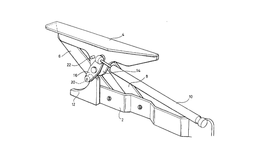
Figure 4 shows an embodiment of the invention which overcomes the above-mentioned
problem. The multi-link hinge is substantially the same as in the conventional hinge, and
the same reference numerals have been applied. In the modified hinge mechanism of
Figure 4, a fixed plate or cam 12, having a specific concave cam profile, is secured to the
fixed hinge member 2.
An enlarged lug 14 is formed on the moveable member 4 from which is pivotally mounted
a thrust lever 16. Instead of the moveable end of the strut 10 being pivoted about the
original point 18 on the moveable member, it is now pivoted about the right hand end of
the lever 16. The opposile end of ~he lever 16 carries a rollcr cam followcr 20 whicl
engages in the cam 12.
Referring now also to Figure 5, this shows the hinge mechanism in the partly open
position. In order to prevent excessive anli-clockwise movcmcnl Or lhc lcvcr 16 rclalivc
CA 0220~719 1997-0~-20
to the moveable member 4, there is provided a stop 22 secured ~o the lug 14 of the
moveable member.
It will be apparent that when initially opening the boot lid from the position shown in
Figure 4, the cam 12 allows the lever 16 to rotate in an anti-clockwise direction relative
to the moveable member 2, thereby enabling the strut 10 to expand and, as a result of the
upward reaction on the cam follower 20, to provide the required upward force to at least
assist in opening of the lid. By the time the cam follower 20 rcachcs thc uppcr cnd of thc
cam 12 the lever 16 abuts the stop 22, and at this stage the inclination of the strut 10 is
sufficiently steep to enable it to continue expanding and to open the lid.
Referring now to Figure 6, this shows how the invention may be applied to a bonnet or
front lid of a car. Here the bonnet 24 is hinged to the body of the car by a single-axis
hinge device (not shown) at each side of the bonnet. A gas strut 26 holds the bonnet in
the open condition shown. Fixedly mounted to the body inside the bonnet compartment
is a ramp or cam 28, generally similar to the cam 12 of the previous embodiment of the
invention.
A lever 30, similar to the previous lever 16, is pivotally mounted on the inside edge of
the bonnet 24, and carries a roller cam follower 32 at its lower end. The other end of the
lever 30 is connected to the outer end of strut 26 at a pivot joint 34.
The operation of the mechanism shown in Figure 6 is similar to that previously described.
Thus in opening the bonnet 24 from the closed position shown in Figure 6A, the cam 28
enables the strut 26 to rotate the lever 30 and thereby continue to open the bonnet 24.
The pivotal joint 34 of the gas strut is preferably arranged to be readily disconnectable,
so Iha~ Ihe bonne~ can be opcncd furlher, for cxamplc in lhc cvcnl lha~ major work
requires to be performed on the engine inside the bonnet.
The precise shape of the cam 12 and 28 has to be carefully chosen in relation to the hinge
geometry, so that a reasonably constant opening force is applicd by lhc slrul lo lhc boo
CA 0220~719 1997-0~-20
lid or bonnet. Conversely, it is important that the cam allows the boot lid or bonnet to
be closed in a smooth manner, and without encountering a sudden increase in the
necessary closing force upon engagement of the cam.
Referring now to Figure 7, there is shown a modification of the cam and cam follower of
Figures 4 and 5.
Here the cam follower is replaced by an involute gear pinion 40, while the cam is replaced
by an inclined rack 42 with involute gear teeth which mesh with the teeth of the pinion.
The bearing for the pinion 40 is arranged to be slightly stiff, so that when the lid of Ihe
boot has been fully opened and the pinion has moved away from the rack 42, it will
remain in the same rotational position as it was upon leaving meshing engagement with
the last tooth of the rack. When the lid is again shut, the pinion will therefore smoothly
re-engage with the rack in its previous rotational position.
Operation of the modified hinge mechanism is as described with reference to Figures 4
and 5, the advantage of the modification being that the pinion will slarl rolating
immediately it re-engages with the rack, whereas in the arrangement of Figures 4 and 5
the cam follower 20 may initially tend to skid on the cam surface 12, due to the high
perpendicular forces exerted via the gas strut 10.
Figure 8 shows a side view of a modified cam arrangement in place of the one described
with reference to Figures 4 and 5. Although similar parts are denoted by the same
reference numerals, it should be noted that the mechanism of Figure 8 is opposite-handed
to that of Figures 4 and 5.
In the embodiment of Figure 8 the cam 12 of Figures 4 and 5 is replaced by a cam 50
which is pivotally mounted on the fixed member 2 of the hinge at the end remote from the
gas strut 10. The cam is biassed in an upward direction by a compression spring 52 which
is mounted on the member 2 and locates around a lug 54 disposed approximately mid-way
beneath the cam. Although the spring 52 is shown as a coiled compression spring, it
could alternatively be replaced by a leaf type spring or even by a rubber block.
CA 0220~719 1997-0~-20
In operation, when fully closing the boot lid, the cam follower 20 engages the free end of
the cam 50, the spring 52 being in its relaxed extended position as shown. Consequently
at this point only a slightly greater closing force is initially encountered.
The n~cess~ry force then increases gradually as the cam is pressed downwardly against
the spring by the follower 20, although the increase is intigrated by the changing geometry
of the lever 16 and strut 10. Conversely, opening of the boot lid also occurs more
smoothly, since a greater opening force is initially available.
Particularly in the case of a boot lid, the profile and inclination of the cams 12, 50 or rack
42 and the general geometry of the mechanism may be so arranged that the lid, once
released, will open without manual assistance. The catch for the boot lid can then be
released remotely from inside the vehicle, without the driver having to go to the back of
the vehicle to open the boot lid. Alternatively it may be preferred, eg for safety reasons,
that releasing the lid allows the mechanism initially only to open the lid partially. A
small manual force will then be required before the mechanism continues lo open the lid
to the fully open condition.