Note: Descriptions are shown in the official language in which they were submitted.
CA 02205728 2002-06-13
-1-
IhTFLATABLL PAOKER KITH PORT COLLAR VALVIhIG
Field of the Invention
The present invention relates to an inflatable packer and particularly to an
inflatable Backer with a h.rge flow path capable of transmitting a cement or
epoxy to
an inflation chamber to inflate the elastomeric packer element. The invention
also
relates to an improved technique for activating an inflatable packer utilizing
mechanically transmitted forces to open a port collar valve for inflating the
packer.
Multiple packers can be reliably inflated in a single trip, and drill out of
plugs is
avoided.
Background of the Invention
Various techniques have been proposed for placing cement in an annulus
between downhole tubulars in order to seal between different zones otherwise
in fluid
communication with the same annulus. In some applications, the placement of a
cement plug in the annulus may be completed by pumping cement downhole and
opening a valve to pump the cement directly into the annulus. In highly
inclined
(non-vertical) wells, gravity tends to cause the pumped cement to fill the
bottom of
the annuls, and a reliable seal between the tubulars is typically not effected
in the
top of the annulus. Since reliable placement of cement may be significantly
affected
by gravity, this technique is not typically utilized in highly deviated or
horizontal
wellbores. U.S. Patent Nos. 2,435,016, 2,659,438, and 3,464,493 each disclose
downhole valves for pumping cement into an annulus about a tubular. U.S.
Patent
No. 2,435,016 discloses a technique capable of multiple stage cementing. U.S.
Patent No. 3,464, 493,discloses a port collar for a well casing to pack a
wellbore with
cement.
In order to achieve a mare reliable seal in the annulus between downhole
tubulars, cement has been used to inflate a packer for sealing this annulus.
The
elastomeric packer element acts as an initial seal between the tubular on
which it is
positioned and the surrounding tubular or the wall of an open hole. An
inflation
chamber radially in~va~~d of the elastomeric packer element serves as a
receptacle for
TAM-491F 1135
CA 02205728 2002-06-13
-2-
the cement or epoxy, which acts as the inflation fluid. Corrosive fluids are
commonly contained in the flow stream of hydrocarbon recovery wells and thus
result
in the potential failure of the sealing function of the elastomeric packer
element over
an extended period of time. Cement or epoxy, once hardened within the
inflation
chamber, thus creates a permanent annular plug between the tubular on wlaich
the
packer is positioned and the surrounding tubular or open hole. U.S. Patent No.
5,488,994 discloses an inflatable packer which utilizes a chemical
accelerating agent
for hardening the cement used to inflate the packer element.
Conventional inflatable packers have valves to inflate the elastomeric packer
element positioned within small diameter ports passing through the sidewall in
the
packer body and to the inflation chamber. Although these packers have been
used
for cementing operations, the small diameter ports and associated valuing tend
to plug
with particles commonly carried by the cement slurry. Accordingly, packers
especially designed far cement plugging operations may use an annular
passageway
between a radially inner sleeve and a radially outer sleeve to reliably
transmit the
cement or epoxy to inflate the packer element. U.S. Patent No. 3,948,322
discloses
a multiple stage packer with a sliding sleeve and an annular passageway for
transmitting cement to inflate the pacl~er element. U.S. Patent No. 4,499,947
discloses an inflatable packer with both first and second sleeves for
.controlling
inflation of the packer element. U.S. Patent No. 5,024,273 discloses a complex
tool
with a stage collar for inflating the packer. U.S. Patent No. 5,109,925
discloses a
multiple stage inflation packer with a rupture disk. U.S. Patent Nos.
5,314,015,
5,315,562 and 5,400,855 each disclose inflation packers with multiple sleeves,
valves,
andJor rupture disks. U.S. Patent No. 5,383,250 discloses an inflation packer
adapted for coiled tubing operations.
The above-described inflatable packers are Complex and thus expensive.
Multiple sleeves, rupture disks, andlor other valves increase the complexity
of the
inflatable packer and generally reduce the flow capacity. Long term
reliability of the
set packer may be questionable since corrosive fluids and/or high temperature
fluids
may attack th.e elastomeric seals which seals the ends of the packer inflation
chamber.
If these elastomeric seals fail prior to curing the cement, a leak path past
the cement
TAM-49IP 1 I 35
CA 02205728 1997-OS-20
-3-
plug may be formed, although that leak path may not be detectable until after
the
packer has been set and the hydrocarbon recovery system is brought into
operation.
Other inflatable packers cannot pressure test the seals to ensure that the
packer
chamber is reliably sealed with the cementatious inflation fluid.
A significant disadvantage of prior art inflatable packers of the type
intended
for inflation with a cementations fluid is that the valuing to the inflation
chamber is
hydraulically activated. A plug or a ball is typically dropped from the
surface for
sealing engagement with a seat, after which a cement slurry is transmitted to
the
packer inflation chamber, followed by another plug or ball. Fluid pressure in
the
well is thus increased to open the valve to the inflation chamber, thereby
allowing the
cement slurry to inflate the sealing element. While plugs or balls have long
been
used to set inflatable packers, the reliability of the setting operation is
particularly
suspect when the packer is used in highly deviated or horizontal wellbores,
since
gravity does not assist in controlled movement of the plug and since plugs do
not
reliably flow past corners or sharp deviations in a deviated well.
After the cement has cured or after another valve of the inflatable packer has
been closed, the cement still within and above the bore of the packer is
drilled out,
along with the plugs or balls, thereby re-establishing a full bore through the
set
packer. Even if the quantity of cement may be precisely controlled to fully
inflate
the packer without excess cement being in the bore, the plugs or balls still
must be
removed to establish full bore capability. With any drill out operation, and
most
commonly with operations involving highly deviated or horizontal boreholes,
there
is a risk that the drill bit may inadvertently penetrate the casing, thereby
causing
significant repair costs and down time.
In other applications, it would be desirable to set the packer in a well along
a casing string which includes perforations or slots in the casing above the
packer.
These perforations or slots need to be closed off or a bypass placed around
the
perforations or slots within the casing for the hydraulically set packer to be
filled with
cement or other inflation fluid. As a practical matter, the cost of
temporarily closing
off or bypassing the perforations or slots are so high that inflatable set
packers are
not frequently used in casing strings which include the slots or perforations.
TAM-49/P 1135
CA 02205728 1997-OS-20
-4-
Another significant disadvantage of prior art inflatable packers is that
multiple
packers cannot be placed along a casing string and each packer reliably
activated
hydraulically to open a valve and inflate the sealing element with cement or
another
inflation fluid. Wiper plugs positioned below and above the cement column are
sized
for sealing engagement with an inflatable packer. As a practical matter,
however, it
is difficult if not impossible to ensure that a wiper plug will properly seat
with its
desired packer but will not inadvertently cause the activation of other
packers through
which the plug passes while flowing down to its desired packer seat. While
different
size plugs may be used, the plugs conventionally seal with the casing to
prevent the
escape of cement from the column as it is pumped downhole to the desired
packer.
As a practical matter, therefore, casing strings which include inflatable
packers
typically cannot reliably inflate more than two hydraulically set packers
within the
casing string and reliably ensure that the wiper plugs do not inadvertently
cause the
opening of an unintended packer positioned along the casing string. If the
valve is
IS inadvertently opened by a wiper plug and cement is unintentionally pumped
into the
inflated packer, the operator at the surface may not realize that the wrong
packer in
the casing string has been inflated until after the cement hardens.
Accordingly, ar.
expensive mill out operation may be required to cure the problem caused by the
inadvertent hydraulic setting of an inflation packer.
The disadvantages of the prior art are overcome by the present invention, and
an improved inflatable packer is hereinafter disclosed which is particularly
well suited
for inflation with cement or an epoxy to form a permanent plug in a wellbore.
The
techniques of the present invention allow for the reliable setting of multiple
inflatable
packers within a casing string, and avoid significant problems involving drill
out of
plugs.
TAM-49/P1135
CA 02205728 2002-06-13
-5-
Summary of the Invention
The invention in one broad aspect provides an inflatable packer for
positioning
along a tubular string and for setting downhole in a wellbore, the inflatable
packer
comprising a sleeve-shaped packer body having an upper end adapted for
interconnection with the tubular string, a lower end, and a central
throughbore, and an
elastomeric packer element radially outward of the packer body for expanded
engagement into one of an inner surface of a large diameter tubular radially
external
to the tubular string and a wall of the wellbore, the elastomeric packer
element and
the sleeve-shaped packer body defining an inflation chamber radially
therebetween.
A valve collar is moveable relative to the packer body to selectively open and
close
fluid communication between the central throughbore and the inflation chamber,
the
valve collar having a stop surface thereon for mated engagement with an
actuating tool
suspended within the tubular string on a work string to open and close the
valve collar
by mechanical manipulation of the work string. A seal is provided for sealing
between the valve collar and the packer body to seal the inflation chamber
from the
throughbore when the valve collar is moved closed.
Another aspect of the invention provides a method of setting an inflatable
packer positioned along a tubular string in a wellbore, the inflatable packer
including
a sleeve-shaped packer body having a throughbore therein and an elastomeric
packer
element radially outward of the packer body, the elastomeric packer element
and the
sleeve-shaped packer body defining an inflation chamber radially therebetween.
The
method comprises securing an actuating tool along a work string, lowering the
actuating tool and the work string through the tubular string, mechanically
engaging
the actuating tool and a valve collar supported on the packer body,
manipulating the
work string to selectively open the valve collar, transmitting an inflation
fluid through
the open valve collar and to the inflation chamber to inflate the packer
element, and
mechanically manipulating the work string to selectively close the valve
collar and seal
the inflation chamber from the wellbore.
CA 02205728 2002-06-13
-SA-
More particularly, the inflatable packer of the present invention preferably
includes
a single valve collar which is opened and closed by forces mechanically
transmitted from the
valve collar which is opened and closed by forces mechanically transmitted
from the
surface to the packer, thereby inflating then subsequently closing off the
packer
inflation chamber. Mechanical forces may be transmitted through a work string
and
a ~ setting tool to open and close the collar. The sliding collar includes a
flange or
other stop member for locked engagement with the setting tool. The work string
may
be slacked off to lower tile collar and open a large port for transmitting
cement from
the work string to the packer inflation chamber. After setting the packer, the
work
string may be pulled up for returning the collar to its upward position while
making
up a metal-to-metal seal both above and below the port and between the collar
and
the packer body, thereby ensuring that corrosive fluids are sealed from the
inflation
chamber. Fluid pressure may subsequently be increased in the annulus between
the
work string and the casing to reverse circulate the cement slurry back to the
surface
through the work string. Accordingly, expensive and time-consuming drill out ,
operations are avoided. By avoiding plug drill out operations, inadvertently
drilling
through the casing string during drill out is eliminated.
Since the valve for controlling opening and closing of the inflation chamber
is mechanically activated, multiple packers positioned along the casing string
may
each be selectively activated at any time. The setting tool includes a profile
for
engagement with the collar of the inflatable packer to be actuated, although
the tool
may be easily raised or lowered past one or more similar inflatable packers
then
positioned at a desired setting for engagement with the desired inflatable
packer to
activate that packer. Multiple packers may thus be reliably set with the same
setting
tool in a single trip of the work string. The packer setting operation may
also.be
used to activate packers positioned along a casing string with perforations or
slots in
the casing string, since the inflation fluid is transmitted to the packer
through a work
string rather than through the casing string.
The integrity of the seals abave and below the port in the packer body may
be pressure tested once the collar is closed and, if necessary, the collar may
be re-
closed until reliable seals are made up. The make up of metal-to-metal seals
between
TAM-49/P 1135
CA 02205728 2002-06-13
-6-
the collar and the packer body ensures that corrosive fluids will not enter
the sealing
chamber, and allows the packer to be reliably used in high temperature
applications.
Accordingly, the present invention seeks to provide an inflatable packer
adapted
far pumping a cementations fluid into the inflation chamber whereby the casing
string
on which the packer is positioned may be opened to full bore without drill out
of
plugs used in the inflation operation. The packer is well adapted for use in
highly
deviated and horizontal bore holes which cannot reliably transmit plugs to the
packer.
The risk of inadvertent drilling a hole in the casing is eliminated by
avoiding the plug
drill out operation. The packer of the present invention includes a valve
collar which
may be reliably operated for opening and closing even when the packer is used
in a
downhole environment wherein the casing string and/or the packer is subject to
high
bending loads which are commonly encountered in highly deviated or horizontal
wells. .
Further, the invention seeks to provide an inflatable packer of the type
wherein the inflation chamber may be sealed by mechanically opening and
closing a
valve collar. Multiple packers may be positioned along the casing string and
each
packer selectively inflated by manipulating a running tool in a single trip of
the work
string. Inflation fluid is transmitted to the packer through the work string,
so that the
packer may be reliably set in a casing string with slots or perforations above
the
packer.
It is a feature of this invention that the inflatable packer includes a single
valve
collar which is mechanically opened and closed vrith sliding movement, thereby
reducing the complexity of the tool. When the collar is moved closed, the seal
between the collar and the packer body may be pressure tested to ensure
reliable
sealing engagement.
Still another feature of this invention is that the opened collar may expose a
plurality of large ports for transmitting cementations fluid to an annular
passageway
extending axially from the collar to the inflation chamber.
Yet another feature of this invention is that the sliding collar includes a
metal-to-metal seal so that the packer may be used in high temperature
applications
with the inflation chamber remaining sealed from the downhole fluids. The
metal-to-
TAM-49/P1135
CA 02205728 2002-06-13
_7
metal seals signif cantly reduce or eliminate the effects of corrosive well
fluid which
deteriorate seals normally provided in packers for sealing the inflatable
chamber.
Long term reliable operation of the packer is enhanced by providing metal-to-
metal
seals between the sliding collar and the packer body.
An advantage of the inflatable packer according io the present invention is
that
the ~ packer may be reliably used in applications wherein elastomeric seals
are
prohibited for downhole tools.. The packer according to the present invention
includes
metal-to-metal seals for sealing between the sliding collar and the packer
body, with
elastomeric seals optionally providing redundant sealing effectiveness and
preferably
being positioned. upstream from the metal-to-metal seals.
Another advantage of the present invention is that the metal-to-metal seals
between the sliding collar and th.e packer body may be formed by slacking off
the
work string and subsequently pulling upward with a Large axial force on the
work
string to jerk the collar upward into sealing engagement with tapered metal
sealing
surfaces on the packer body. By providing a low angle engagement surface
between
the metal collar and the metal packer body and by supplying a sufficient axial
force
to the work string, the likelihood of the sealed collar subsequently
inadvertently
dropping to an open position is eliminated or substantially reduced.
'These and further aspects, features, and advantages of the present invention
will
become apparent from the following detailed description, wherein reference is
made to the
figures in the accompanying drawings.
CA 02205728 2002-06-13
_8-
Brief Descn_ption of the Drawings
Figure lA is a pictorial view of a well including a casing string with a lower
portion of an upper packer positioned thereon and with a work string passing
through
the upper packer. Positioned below the upper packer is an actuating tool for
operating a lower packer positioned on the casing string below the actuating
tool.
Figure IB generally illustrates a lower packer according to the present
invention adapted for being inflated with a cementatians fluid in the work
string
shown in Fig. IA.
Figure 2 is a detailed cross-sectional view of a portion of the inflatable
packer
generally shown in Fig. IB. The collar on the right side of the centerline in
Fig. 2
is shown in the closed position, and the collar on the Ieft side of the
centerline is
shown in the opened position.
Figure 3 is an enlarged cross-sectional view illustrating the metal-to-metal
sealing engagement of the collar and the packer body when the collar is in the
closed
position.
CA 02205728 2004-05-21
-9-
Detailed Description of the Preferred Embodiments
Figure 1 A depicts an exemplary application for the present invention.
Inflatable
packers are commonly used in hydrocarbon recovery operations for isolating
geological zones. A borehole B may be drilled through an upper hydrocarbon
zone
UHZ, through a non-hydrocarbon bPzring shale zone SZ, and then through a lower
hydrocarbon zone LHZ. The inflatable packer may thus be used to isolate these
zones and thereby maximize recovery of hydrocarbons. Although Fig. lA depicts
the
wellbore B as being vertical, those skilled in the art will appreciate that
the inflatable
packer of the present invention is particularly well suited for use in highly
deviated
and horizontal boreholes. In those applications, the borehole may still
traverse
geological zones, and the inflatable packer may be used to fluidly isolate
zones from
each other. Highly inclined or horizontal wellbores thus typically pass
through
various perme<~ble layers which contain .hydrocarbons, with the permeable
layers
being separated by impermeable layers which typically include shale or
granite. The
hydrocarbon producing layers are fluidly isolated in order to selectively
produce the
hydrocarbons. According to the method of the invention, this isolation is
achieved
by using an inflatable packer to seal between the outside of the casing C and
the open
borehole B. In order to achieve long term sealing effectiveness, the
inflatable
chamber of the packer may be filled with a cementatious fluid.
Figure lA depicts the lower end of an inflatable packer positioned along a
casing string C and borehole B. The packer I6 is shown in its inflated
position so
that the annulus between the casing C and the borehole wall is plugged by the
set
packer 16. For this exemplary embodiment, the fluid used to inflate the packer
is a
cementatious fluid ~~~hich is a slurry when pumped into the packer, and
hardens to
form a permanent plug. The term "cementatious fluid" as used herein refers to
any
tyre of slurry wl-~ich may be used in downhole operations to form a plug,
including
compositions such as a cement slurry, a curable polymer or plastic, or an
epoxy. As
sho~m in Fig. lA, the inflatable packer 16 thus isolates the UHZ from the SZ.
Packer 16 may he identical in construction and operation to the inflatable
packer 10
discussed below and generally shown in Fig. 1 B.
TAM-49/P 1135
CA 02205728 2004-05-21
-10-
The lower end of the packer 16 is interconnected with the casing C by
conventional threads 18. The casing C extends through the SZ, and supports
another
inflat<lblc packer 10 positioned in the well (see Fig. 1B) so that the
inflatable packer
element 120 is generally at the interface between the SZ and the LHZ. Those
skilled
in the art will appreciate that numerous inflatable packers may be positioned
along
a casing string in a wellbore, and that only two packers are shown in Fig. lA
for
simplicity. The packers of the present invention are designed such that a
number of
packers may be positioned axially at selected locations along a casing string,
and each
packer may be selectively inflated as described here<lfter. Also, those
skilled in the
IO art should appreciate that the term "casing" or "casing string" as used
herein refers
to any tubular member of the type which may be positioned downhole for
supporting
an inflatable packer.
Referring to Fig. IB, the inflatable packer 10 is shown in its run-in or
deflated
position. Packer 10 comprises an upper body 12 which is discussed subsequently
and
supports the valve collar, and a lower body 14 which includes an elongate
elastomeric
packer element 120 which inflates in a conventional manner. The upper body 12
of
the packer is thus connected to the casing C by threads 19, and the lower body
14 is
similarly interconnected with casing C by threads 18. The term "elastomeric
packer
element" or "packer element" as used herein refers to any type of generally
tubular
bladder which may be inflated during actuation of the packer. Elastomeric
packer
elements are well known in the art, and numerous such packer elements are
generally
disclosed in the prior art discussed earlier.
Figure lA also depicts a work string WS positioned within the casing C and
passing through the throughbore in the packer 16. The term "work string" as
used
herein refers to any type of tubular string conventionally used to
mechanically set
downhole tools, including tubing strings interconnected by threaded
connections or
coiled tubing. Secured to the work string WS is a actuation tool 20 which as
depicted
is positioned below the packer 16. The work string WS may also extend below
the
actuating tool 20, and includes an internal bore or flow path which is sealed
from the
interior of the casing string C. Those skilled in the art will appreciate that
the work
string WS may be lowered so that the tool 20 is positioned for activating the
packer
TAM-49/P 1135
CA 02205728 2004-05-21
-11-
as discussed subsequently. Actuating tools 20 are well known in the art and
accordingly details regarding the actuating tool 20 are not discussed herein.
A
suitabi_e actuating tool 20 according to the present invention for activating
an
TM
inflatable packer is the TAM Combination Tool.
5 Internal to the body of the inflatable packer 10 is a collar 86 which is
movable
along the axis of the packer to allow exposure of a port from the interior of
the
casing to the inflation chamber radially within the expandable packer element.
Fixed
tubes create an annular passageway 76 for flow of the inflation fluid from the
purl
into the inflation chamber. The inflatable element 120 is attached to the
outer tube,
10 while the casing is attached to the inner tube for supporting the tensile
loads
transmitted through the packer. A sub 122 is attached to a lower end of the
inflatable
element to provic~o an outer seal with the casing at the lower end of the
inflation
chamber.
The collar 86 as disclosed herein is a sliding sleeve which is opened and
closed vrith an axial motion transmitted to the sleeve by the setting tool.
Referring
again to Fig. lA, the setting tool 20 includes dual opposing seal cups 42 and
54 and
contains spring-loaded dogs 58 for opening and closing the collar. The setting
tool
also cor_tains an internal bypass to facilitate running in and cut of the
hole. A
shear choke sub may be incorporated in the setting tool for quick filling of
the work
20 string and dumping the work string fluid when the packer inflation job is
complete.
The valve collar may alternatively be opened and closed by torque transmitted
to the collar through the setting tool. The collar may thus be opened with
left-hand
torque and closed with right-hand torque transmitted through the work string
WS.
The collar includes slots to receive spring-loaded dogs on the setting tool to
provide
a positive indication that the setting tool has landed in the collar. The
setting tool
will not pass through the collar while the dogs are engaged. Multiple packers
can
thus be run on one casing string and each packer selectively opened and closed
in a
single trip of the work string and the setting tool.
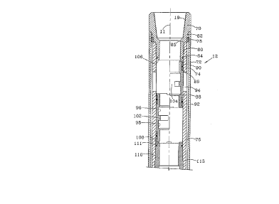
Referring now to Fig. 2, the upper bodv 12 is depicted with the components
on the right side of the centerline 11 in the valve closed or run-in position,
and the
components on the left side of the centerline I1 shown in the valve open or
inflated
TAM-49/P 1135
CA 02205728 1997-OS-20
-I2-
position. The upper sub 70 of the packer 10 includes conventional threads 19
for
threaded engagement with the casing C. An outer tube 72 extends downwardly
from
the sub 70 and may be interconnected therewith by threads, keys or other
conventional securing members 78. An inner tube 74 also generally extends
downwardly from the sub 70, and is interconnected therewith by threads or
other
conventional securing members 80. The outer tube 72 is sealed to the sub 70 by
o-
ring seal 82, which prevents well fluids in the borehole B from communication
with
the interior of the packer 10. O-ring seal 84 and metal-to-metal seal 85
similarly seal
between the sub 70 and the inner tube 74. As shown in Fig. 2, an elongate
annulus
76 is thus formed between the outer diameter of the tube 74 and the inner
diameter
of the tube 72. One or more circumferentially spaced radial ports 94 are
provided
within the inner tube 74. Ports 94 are normally blocked by the valve collar
86.
When the valve collar 86 is open, as shown on the left side of Fig. 2, fluid
from the
work string WS may pass through one or more ports 94 and then through the
annular
passageway 76 to inflate the packer, as explained subsequently.
The valve collar 86 is a sleeve-shaped member which is axially moveable from
the open position, as shown on the left side of Fig. 2, to the closed
position, as
shown on the right side of Fig. 2. The opening and closing of the valve collar
86
may be repeated as desired. When in the closed position, the upper end of the
valve
collar 86 may engage the stop surface 106 formed at the lower end of the sub
70.
When in the fully opened position, the lower end of valve collar 86 may
similarly
engage the stop surface 108 on the sub 110. The valve collar includes an upper
annular seal 90 for sealing engagement between the valve collar and the inner
cylindrical surface 88 of the inner tube 74 and above the one or more ports
94.
When the valve collar is in the closed position, a lower elastomeric annular
seal 92
provides similar sealing engagement bet<veen the valve collar and the inner
tube 74
at a position axially below the one or more ports 94. VaTlollS types of
elastomeric
sealing members may be used in the valve collar according to the present
invention,
including seals fabricated from rubber and plastics.
The valve collar 86 includes an annular upper recess 96 and an annular lower
recess 98 with a circumferentially spaced projection 102 therebetween. As
shown in
TAM-49/P I 135
CA 02205728 1997-OS-20
-13-
Fig. 2, the projection 102 does not extend circumferentially fully around the
valve
collar, and instead one or more circumferential spacings 104 between
projections 102
are provided. The projections 102 and the spacings 104 cooperate, as explained
subsequently, so that the actuation tool may be mechanically interconnected to
the
valve collar 86, but also allow the actuation tool 20 to be rotated and moved
axially
past the valve collar 86 and through the inflatable packer 10 for actuating
another
inflatable packer positioned along the casing string C either above or below
the
packer I0.
The lower end 14 of the inflatable packer 10 is functionally equivalent to
various types of infla table packers, and accordingly is only generally shown
in Fig.
1B. The lower end of the inner tube 74 is interconnected with the sub 110 by
threads
112 or other conventional securing members. O-ring seal I 1 I and metal-to-
metal seal
113 provide for reliable sealing between inner tube 74 and sub 110. The Lower
end
of sub 110 is in threaded engagement with mandrel 116 which extends axially
downv~ard to a position below the elastomeric packer element 120. The lower
end
of the mandrel 116 includes conventional threads 18 for threaded engagement
with
the casing C. Accordingly, the sub 70, the inner tube 74, the sub 110, and the
mandrel 116 provide a structural interconnection between the casing string
above the
packer 10 and the casing string below the packer 10.
The annular passageway 76 as shown in Fig. 2 thus continues downward
between the sub 110 and the outer tube 72. This flow passageway then extends
radially inward between the mandrel 116 and the upper packer sub 118, then
into the
inflation chamber between the packer element 120 and the mandrel 116. The
upper
packer sub 118 is threadably connected to the lower end of the outer tube 72
by
conventional threads 115, and is sealed to the outer tube by an o-ring seal
117. For
the embodiment as shown herein, the upper sub 118 is thus axially fixed with
respect
to the casing C. A lower packer sub I22 is provided at the lower end of the
elastomeric packer element 120, and includes a seal 124 for dynamic sealing
engagement with the outer surface of the mandrel 116. During inflation of the
packer, the lower packer sub 122 may move axially upward toward the upper
packer
sub 118 to accommodate expansion of the elastomeric packer element 120.
TAM-49/P 1135
CA 02205728 1997-OS-20
-14-
Cementatious fluid typically includes particles which tends to plug small
valves or
passageways with small diameters. Also, cementatious fluid which is pumped at
high
velocities through small valves and small diameter passageways corrodes the
valves
and passageway walls during the inflation process. These problems are thus
avoided
by providing one or more large diameter inlet ports 94 and an annular
passageway
76 fluidly connecting the inlet ports 94 with the packer inflation chamber.
According
to the present invention, the flow through area of the one or more inlet ports
94 is
at least 0.15 square inches, and preferably is at least 0.25 square inches. A
cement
slurry with solid particles will thus reliably pass through the inlet ports 94
and the
annular passageway 76 and then to the packer inflation chamber without
plugging the
flow path.
When inflation packers are set by plugging operations as discussed above, the
well operator may be unsure which packer is being inflated. According to the
present
invention, the actuating tool 20 at the end of work string WS is used to open
and
close the valve collar 86. Accordingly, the payout length of work string WS
may be
used to reliably determine which packer positioned along the casing string is
being
acted upon by the tool 20 to open and close the valve collar. If desired, a
conventional locator sub may also be run in with the actuating tool 20 to
further
ensure the position of the tool 20 within the well and thus the reliable
operation of
the desired inflatable packer.
The actuating tool 20 includes one or more locking dogs 58 which are biased
radially outward by springs 62. The dogs 58 may thus move radially relative to
the
actuator body 52, and together define an exterior profile for locked
engagement with
the valve collar 86. The radially inward surface of the valve collar 86 thus
includes
spaced apart grooves 96 and 98 separated by a partial ring or flange 102
having upper
and lower stop surfaces thereon. The dogs 58 thus fit within a respective
groove 96,
98 to mate with the valve collar 86 so that axial forces may be reliably
transmitted
from the work string WS to a tool 20 and then to the valve collar 86 to open
and
close the collar. The spring biased dogs 58 also provide a positive indication
that the
tool 20 is mechanically interconnected with the valve collar. Separate upper
and
TAM-49/P 1135
CA 02205728 1997-OS-20
-15-
lower dogs may be provided, or upper and lower dogs on a unitary. component 58
may be separated by groove 60 which fits within partial flange 102.
V~lhen a tool 20 is interconnected to the valve collar 86, the upper seal cups
42 and the lower seal cups 54 will sealingly engage the packer body. When the
tool
20 is interconnected with the valve collar 86, the operator may slack off the
work
string WS, thereby allowing gravity and compressive loads (weight of the WS)
to
drop the tool 20 and thus simultaneously lower the valve collar 86 to the
opened
position and open the sliding valve 50 internal of actuator body 54 so that
ports 51
are in fluid communication with ports 52. Cementatious fluid from the bore in
the
work string WS may then be pumped through the work string WS so that the
cementatious fluid flows through ports 51 in sliding valve 50 and through
ports 52 in
actuator body 54, then into the open port 94 in sleeve 74 and down the annular
passageway 74 to inflate the packer element 120. Since fluid pressure is not
required
in the annulus between the work string WS and the casing C, this inflation
operation
may be accomplished even if the casing string above the packer is slotted or
perforated.
Once the packer 10 is inflated, the operator may pull up on the work string
WS, thereby raising the tool 20 and returning the valve collar 86 to the
closed
position. During this upward pull, a tensile applied to the work string WS
will make
up the metal-to-metal seals between the valve collar and the work string, as
shown
in Fig. 3. The packer body thus includes a tapered upper metal sealing surface
136
and a tapered lower metal sealing surface 132 each formed at a relatively low
angle
relative to the axis of the packer body. The valve collar 86 includes
corresponding
tapered upper and lower metal sealing surfaces 134 and 130. The sealing forces
used
to reliably make up the metal-to-metal seals may be controlled by regulating
the
upward pull on the work string WS and by maintaining a desired cam angle
between
the tapered metal-to-metal sealing surfaces.
After the operator pulls up on the work string WS to close the valve 86, fluid
pressure may be increased on the bore of the work string WS to reliably test
the
integrity of the closed valve collar. If there is any leakage between the
closed valve
collar and the packer body, fluid pressure in the work string will slowly
decrease.
TAM-49/P 1135
CA 02205728 1997-OS-20
-16-
In that event, the operator may slack off the work string to at least
partially open the
valve collar 86, then again pull up on the work string with a higher tensile
force to
form a more effective metal-to-metal seal between the valve collar and the
packer
body. The relatively high forces transmitted through the work string to the
valve
S collar when forming the metal-to-metal seal may result in a minimal amount
of metal
deformation or galling of these metal sealing surfaces. This galling is not
undesirable, however, since this action may be used to practically ensure that
the
valve collar 86, once reliably closed, will not inadvertently thereafter open
after the
actuating tool 20 is moved to a new location in the well.
The use of metal-to-metal seals between the valve collar and the packer body
is highly desirable for the long term reliability of the inflated packer to
ensure that
well fluids which normally deteriorate elastomeric seals cannot enter the
interior of
the inflation chamber. It should be understood, however, that elastomeric
upper
annular seal 90 and elastomeric lower annular seal 92 may also be provided for
sealing between the valve collar and the packer body. These elastomeric seals
provide for redundant sealing, and effectively prevent well fluids from
initially
contaminating the metal-to-metal sealing surfaces. Over an extended period of
time
and after the cementatious fluid in the set packer is cured, the well fluids
may attack
and effectively destroy the sealing effectiveness of the elastomeric seals.
Well fluids
passing by the elastomeric seals 90 and 92 will not be able to enter the
inflation
chamber, however, because the reliable metal-to-metal seals are provided
fluidly
downstream from the elastomeric seals.
As previously noted, the partial ring or flange 102 does not extend
circumferentially completely about the valve collar. The spacing 104 between
ring
segments allows an operator to selectively engage the locking dogs 58 with the
valve
collar 86, or alternatively to pass the tool 20 vertically upward or downward
past one
inflatable packer for reliable actuation of either an upper or a lower
inflatable packer.
As previously indicated, the biased dogs 58 allow the well operator to
reliably
determine if the dogs 58 have locked onto a particular valve collar 86. If
locking
engagement between the dogs 58 and that valve collar is not desired, the
operator
may rotate the work string WS and thus the tool 20 and the locking dogs 58 so
that
TAM-49/P 1135
CA 02205728 1997-OS-20
-17-
the locking dogs 58 are circumferentially positioned in line with spacing 104.
With
the dogs 58 circumferentially aligned with the spacings 104, tool 20 may be
easily
passed by the valve collar of one inflatable packer and then repositioned for
engagement with a similar valve collar of another inflatable packer positioned
along
the casing string. In this manner, any number of inflatable packers positioned
along
a casing string may be selectively actuated to open and close the inflation
chambers
with a single trip of the work string WS within the well.
Once a particular valve collar 86 is opened and cementatious fluid is pumped
into the inflation chamber to inflate the desired packer, the valve collar 86
may then
be mechanically returned to the closed position, as described above. Once
closed,
the operator rnay reliably remove excess cementatious fluid within the work
string
WS by a reverse circulating operation. During this process, fluid pressure is
increased in the annulus between the work string WS and the casing C. This
increased fluid pressure will enter the interior of the tool 20 (valve 50 is
still open),
IS thereby forcing the excess cementatious fluid in the bore of the work
string WS
upward to the surface. The excess cementatious fluid may thus be reverse
circulated
to the surface in a simple and reliable manner. Most importantly, drill out of
plugs
and excess cementatious fluid is not required. The high cost and numerous
problems
which conventionally accompany drill out operations may thus be avoided
according
to the technique of the present invention.
Various modifications to the inflatable packer and to the technique as
described
above may be made without departing from the concepts of the present
invention.
If desired, for example, an actuating tool may include dogs with a profile for
mated
engagement with only selected ones of various valve collars associated with
inflatable
packers positioned within a well, thereby ensuring that the actuating tool
will always
pass by a valve collar with a profile which is not intended for mating
engagement
with that actuating tool. The packer body on which the port collar is mounted
may
be provided with a locator sub for ensuring the position of the port collar
and/or the
packer within the well. While the present invention has particularly described
for the
application wherein the packer is inf ated with a cementatious fluid which
then cures
and hardens within the well, those skilled in the art will appreciate that the
concepts
TAM-49/P 1135
CA 02205728 1997-OS-20
-18-
of the present invention may also be applied for inflating a packer with any
type of
inflation fluid.
In the embodiment discussed above, the valve collar 86 is positioned axially
above the elastomeric packer element 120. The valve collar 86 could, however,
be
spaced axially below the packer element. As previously noted, the valve collar
could
also be opened and closed in response to rotation. Mechanical forces
transmitted
through the work string to an actuating tool may thus result in sufficient
torque
applied to the valve collar to open and close the valve collar. Axial forces
transmitted through the work string to the actuating tool may still be used,
if desired,
to reliably make up a metal-to-metal seal between the valve collar and the
packer
body.
The port collar as disclosed herein may also be operated by an actuating tool
to selectively pump a cementatious fluid from a work string through the casing
and
then into an annulus about the casing. The metal-to-metal seal as disclosed
herein
would then desirably be formed between the valve collar and a mandrel
positioned
along the casing string and supporting the port collar. In some applications,
an
inflatable packer will thus not be necessary to form a reliable downhole
cementatious
Plug.
The foregoing disclosure and description of the invention is illustrative and
explanatory thereof, and it will be appreciated by those skilled in the art
that various
changes in the size, shape and materials as well as in the details of the
illustrated
construction or combinations of features of the various inflatable packer
elements and
the method of actuating a packer and removing excess cementatious fluid from
the
interior of the work string WS discussed herein may be made without departing
from
the spirit of the invention.
TAM-49/P1135