Language selection

Search

Patent 2205787 Summary

Third-party information liability

Some of the information on this Web page has been provided by external sources. The Government of Canada is not responsible for the accuracy, reliability or currency of the information supplied by external sources. Users wishing to rely upon this information should consult directly with the source of the information. Content provided by external sources is not subject to official languages, privacy and accessibility requirements.

Claims and Abstract availability

Any discrepancies in the text and image of the Claims and Abstract are due to differing posting times. Text of the Claims and Abstract are posted:

  • At the time the application is open to public inspection;
  • At the time of issue of the patent (grant).
(12) Patent Application: (11) CA 2205787
(54) English Title: DEVICE FOR THE MUTUAL FIXING OF FERROMAGNETIC CORES AND CARRIERS FOR EL ECTRICAL CONDUCTORS IN INDUCTIVE COMPONENTS
(54) French Title: DISPOSITIF POUR LA FIXATION MUTUELLE DE NOYAUX FERROMAGNETIQUES ET DE SUPPORTS POUR CONDUCTEURS ELECTRIQUES DANS DES COMPOSANTES INDUCTRICES
Status: Dead
Bibliographic Data
(51) International Patent Classification (IPC):
  • H01F 41/02 (2006.01)
  • H01F 17/04 (2006.01)
  • H01F 27/26 (2006.01)
(72) Inventors :
  • FAUST, BERNHARD (Germany)
(73) Owners :
  • SIEMENS MATSUSHITA COMPONENTS GMBH & CO. KG (Germany)
(71) Applicants :
  • SIEMENS MATSUSHITA COMPONENTS GMBH & CO. KG (Germany)
(74) Agent: FETHERSTONHAUGH & CO.
(74) Associate agent:
(45) Issued:
(22) Filed Date: 1997-05-22
(41) Open to Public Inspection: 1997-11-24
Availability of licence: N/A
(25) Language of filing: English

Patent Cooperation Treaty (PCT): No

(30) Application Priority Data:
Application No. Country/Territory Date
19621126.3 Germany 1996-05-24

Abstracts

English Abstract


Device for the mutual fixing of ferromagnetic
cores and carriers for electrical conductors in inductive
components, with a slotted annular spring (10) made from
metallic material and arranged between the ferromagnetic
core and the coil former.


French Abstract

Dispositif pour la fixation mutuelle de noyaux ferromagnétiques et de supports pour conducteurs électriques dans des composantes inductrices, avec un ressort annulaire à rainure (10) fait d'un matériau métallique et disposé entre le noyau ferromagnétique et le corps de la bobine.

Claims

Note: Claims are shown in the official language in which they were submitted.


- 4 -
Claims

1. Device for fixing ferromagnetic cores (2, 3) and
carriers (1) for electrical conductors in inductive
components, particularly in inductors designed for SMD
assembly, characterized in that a slotted annular spring
(10; 20; 30; 40; 50; 60) made from metallic material is
provided in a gap between the ferromagnetic core (2, 3)
and the carrier (1) for electrical conductors.
2. Device according to Claim 1, characterized in
that the material of the annular spring (10; 20; 30; 40;
50; 60) is a non-ferromagnetic material.
3. Device according to Claim 1 and/or 2,
characterized in that the annular spring is an externally
toothed annular spring (10, 11, 12; 30, 31, 32).
4. Device according to Claim 1 and/or 2,
characterized in that the annular spring in an internally
toothed annular spring (20, 21, 22).
5. Device according to one of Claims 1 to 4,
characterized in that the toothing (12; 22) of the annular
spring (10, 11, 12; 20, 21, 22) is a slotted toothing.
6. Device according to one of Claims 1 to 4,
characterized in that the toothing (32) of the annular spring
(30, 31, 32) is a toothed-ring toothing.
7. Device according to Claim 1, characterized in
that the annular spring is a cup spring (40, 41; 50, 51).
8. Device according to Claim 7, characterized in
that the cup spring is an annular spring (40, 41) curved
in the annular plane.
9. Device according to Claim 7, characterized in
that the cup spring is an annular spring (50, 51) rotated
in the annular plane.
10. Device according to Claim 7, characterized in
that the cup spring (60, 61, 62) is formed from two
curved annular segments (62) connected to one another at
one end.
11. Device according to one of Claims 1 to 10,
characterized in that the carrier (1) for electrical
conductors is a coil former.

- 5 -


12. Device according to one of Claims 1 to 10,
characterized in that the carrier for electrical
conductors is an at least single-layer printed board.

Description

Note: Descriptions are shown in the official language in which they were submitted.


CA 0220~787 1997-0~-22

GR 96 P 1519

Description

Device for the mutual fixing of ferromagnetic cores and
carriers for electrical conductors in inductive
components.
The present invention relates to a device for the
mutual fixing of ferromagnetic cores and carriers for
electrical conductors in inductive components.
In the case of pin-type designs of inductive
components, the core and the coil former are clamped by
means of plastic insulating discs for the purpo~e of
mutual fixing, the core being additionally soldered into
a circuit board via a clip for permanent fastening. This
presents the difficulty that plastic in~ulating discs do
not have long-term stability and are unsuitable for
temperatures which occur during soldering operations.
Furthermore, the core and the coil former can
also be fixed relative to one another by adhesive bond-
ing, this being the case particularly in SND inductors.
However, this is comparatively expensive and is not
reliable in terms of the process employed and, further-
more, there is no possibility of remach;n;ng or
recycling.
The first-mentioned possibility of clamping the
core and coil former in pin-type designs by means of
plastic insulating discs is illustrated in Figure 7 of
the drawings. A design of this kind is known, for
example, from the applicant's manual "Ferrite und
Zubehor" ~"Ferrites and Accessoriesn], 1994 edition, page
215.
Figure 7 shows the essential parts of an induc-
tive component in the form of an exploded illustration.
The component possesses a coil former 1 and two magnetic-
core halves 2, 3 which are placed onto the coil former 1
and are held on the coil former by means of clips 5. A
first insulating disc 4 is inserted between the coil
former 1 and the upper core half 2. A second insulating
disc 6 is placed onto the underside of the lower core
half 3. When the component is being assembled by means of

CA 0220~787 1997-0~-22

GR 96 P 1519 - 2 -
the clip8 5 and when the component is being fitted, for
example, into a circuit board, the coil former 1 and the
core halves 2, 3 are fixed relative to one another so as
to be secure against mutual rotation.
The object on which the present invention i8
based i8 to provide a fixing of the abovementioned type
which is free of play and secure against mutual rotation
and which has long-term stability and is still resistant
even to high temperatures, such as occur, for example,
during soldering.
In a device of the type mentioned in the intro-
duction, this object is achieved, according to the
invention, by means of the measures according to the
characterizing clause of Patent Claim 1.
Developments of the invention are the subject of
subclaims.
The invention is explained in more detail below
by means of exemplary embodiments illustrated in the
figures of the drawing. In this, Figures 1 to 6 show, in
each case, an embodiment of a fixing spring according to
the invention, and Figure 7 show~ the already explained
pin-type design of an inductive component.
According to Figure 1, an annular spring 10
having a slot 11 i~ provided. This annular spring 10, 11
is produced from metallic material. The metallic material
may be a non-ferromagnetic or slightly ferromagnetic
material. The slot 11 is essential for an electrical
interruption of the spring body.
The spring 10 has an externally ~lotted toothing
12, Figure 1 indicating a rotation of the toothing about
an axis r~nn;ng in the radial direction, thereby bringing
about the spring effect.
In the case of an annular spring 20 having a slot
21 according to Figure 2, an internally slotted toothing
22 is provided, a rotation of the toothing being provided
once again for the purpose of implementing the spring
effect.
In the embodiment of a spring 30 having a slot 31
according to Figure 3, a toothing 32 in the form of a

CA 0220~787 1997-0~-22

.
GR 96 P 1519 - 3 -
toothed ring is provided, the teeth likewise being
rotated again in order to implement the spring effect.
Figures 4A and 4B show an annular spring 40
having a slot 41 in the form of a cup spring with a
curvature which i8 evident from Figure 4B and which
ensures the spring effect.
Figures 5A and 5B show an annular spring 50
having a slot 51, in which spring the spring body is
rotated in the annular plane in the way evident from
Figure 5B.
Figure 6 shows a cup spring 60 having a slot 61
in the form of annular segments which are connected to
one another at one end and which have a curvature (not
illustrated in any more detail) perpendicularly to the
drawing plane for the purpose of implementing the spring
effect.
The springs illustrated in Figures 1 to 6 can be
used, for example instead of the insulating disc 4
according to Figure 7, for fixing the coil former 1 and
the coil halves 2, 3 relative to one another.
It must be pointed out that the carrier for
electrical conductors does not have to be exclusively a
coil former of the type illustrated in Figure 7. It may
also be a single-layer or multi-layer printed board.
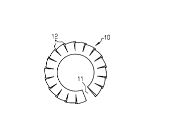
Representative Drawing
A single figure which represents the drawing illustrating the invention.
Administrative Status

For a clearer understanding of the status of the application/patent presented on this page, the site Disclaimer , as well as the definitions for Patent , Administrative Status , Maintenance Fee  and Payment History  should be consulted.

Administrative Status

Title Date
Forecasted Issue Date Unavailable
(22) Filed 1997-05-22
(41) Open to Public Inspection 1997-11-24
Dead Application 2000-05-23

Abandonment History

Abandonment Date Reason Reinstatement Date
1999-05-25 FAILURE TO PAY APPLICATION MAINTENANCE FEE

Payment History

Fee Type Anniversary Year Due Date Amount Paid Paid Date
Application Fee $300.00 1997-05-22
Registration of a document - section 124 $100.00 1997-05-22
Owners on Record

Note: Records showing the ownership history in alphabetical order.

Current Owners on Record
SIEMENS MATSUSHITA COMPONENTS GMBH & CO. KG
Past Owners on Record
FAUST, BERNHARD
Past Owners that do not appear in the "Owners on Record" listing will appear in other documentation within the application.
Documents

To view selected files, please enter reCAPTCHA code :


To view images, click a link in the Document Description column. To download the documents, select one or more checkboxes in the first column and then click the "Download Selected in PDF format (Zip Archive)" or the "Download Selected as Single PDF" button.

List of published and non-published patent-specific documents on the CPD .

If you have any difficulty accessing content, you can call the Client Service Centre at 1-866-997-1936 or send them an e-mail at CIPO Client Service Centre.


Document
Description 
Date
(yyyy-mm-dd) 
Number of pages   Size of Image (KB) 
Abstract 1997-05-22 1 11
Cover Page 1997-12-30 1 31
Description 1997-05-22 3 120
Claims 1997-05-22 2 49
Drawings 1997-05-22 2 33
Representative Drawing 1997-12-30 1 3
Assignment 1997-05-22 5 198