Note: Descriptions are shown in the official language in which they were submitted.
CA 0220~83l l997-0~-2l
WO 96/21483 PCT/US95/16665
SELF RETRACTING MEDICAL Nl~EDLE APPAR~TUS AND METHODS
Continuation
This application for patent is a continll~tion-in-part of co-pendin~ U.S. PatentApplication Serial Number 08/455,514 filed May 31. 1995~ which is a continuation of
U.S. PatentNo. 5,480,385, issued January 2, 1996 and of U.S. Patent Application Serial
Number 08/436,976 filed May 8, 1995, and U. S. Patent Application Serial Number
08/484.533 filed June 7, 1995. which are now allowed and are continuations-in-part of
U.S. Patent Application Serial Number 08/370,728 filed January 10, 1995~ the
disclosures of which are specifically incorporated herein.
Field of Invention
This invention relates generally to medical needle apparatus and methods and
particularly to an al.p~ s comprising medical needles which are self-retracting from
an extended position at which the needle is used to a retracted position where the needle
is fully withdrawn and encased within a housing for safe disposal. Further. the invention
is related to medical products which may only be used once to elimin~te cross
cont~min~tion from one patient to another and to those medical products which have
sterile parts inherently protected from cont~min~tion without the need of additional
packaging apparatus.
Prior Art
Problems associated with inadvertent needle sticks are well known in the art of
blood withdrawal, tr~n~clçrm~l medication injection, catheter emplacement and other
medical procedures involving uses of medical needles. Ever increasing attention is being
paid to needle stick problems due to the contemporary likelihood of being exposed to
AIDS and Hepatitis.
'5 Commonly, procedures involving needle withdrawal require a technician to use
one hand to place pressure at the wound site where a needle is being withdrawn while
removing the needle apparatus with the other hand. It is common practice for a tending
technician to give higher priority to care for the wound than is given to disposal of a
CA 0220~831 1997-0~-21
WO 96/21483 PCT/US95116665
needle. Such priority either requires an available sharps container within ready reach or
another means for safe disposal without leaving the patient's side. Providing adequate
care is often compounded by patient condition and mental state (e.g. in burn units and
psychiatric wards). Under such conditions, it is often difficult, if not impossible, to take
S ~plopl;ate procedures to properly dispose of a used. exposed needle while caring for a
patient.
Widespread knowledge and history associated with needle care and disposal
problems have resulted in the conception and disclosure of a large number of devices,
each of which represents an attempt to provide not only a solution to the problem of
10 needle sticks, but a device which is commercially viable (i.e. cost and price competitive
with currently used non-self retracting devices). Though some devices describe
application in the area of blood withdrawal (see U.S. Patents No. 4,850,374 (Nydia Diaz-
ramos) and 5,195,985 (Hall)), most contemporary related art is directed toward syringes
and like devices. Related art may be broadly classified into two categories, devices
15 which operate manually and devices which comprise self-contained needle retraction.
Examples of m~nll~lly operated medical needle devices are provided in U.S.
Patents numbered 4,676,783 (Jagger et al.), 4,83~936 (Schroeder), 4,909,794 (Haber),
4,978,340 (Terrill et al.), 4,995,870 (Baskas), 5,098,402 (Davis), 5,180.370 (Gellespie),
5,188,599 (Botich et al.), 5,195,985 (Hall), 5,205,823 (Zdeb), 5,205,824 (Mazur),
20 5,215.533 (Robb), and 5,256,153 (Hake). Manual withdrawal is generally a two-handed
procedure, making wound care a secondary step or requiring an added medical
technician. Exarnples of self-retracting devices are found in U.S. Patents numbered
4,946,446 (Vadher), 4,955.870 (Ridderheim et al.), 4,966,593 (Lennox), 4,988.339(Vadher), 4,994,034 (Botich et al.), 5,114,404 (Paxton et al.), 5,147,303 (Martin),
25 5.092,853 (Couvertier), 5,246,428 (Falknor), 5.254,099 (Karacina), and 5,267,976
(Guerineau et al.). Guerineau et al. discloses self-retraction resulting from a vacuum
force while others disclosed above generally disclose self-retraction resulting from
release of a cocked or biased spring.
Generally. other than acceptance of the type of operation offered by such devices.
30 commercial viability is dependent upon manufacturing cost. Purchase decisions in the
area in which these devices are used are very cost sensitive. If gains in either
CA 0220Ct831 1997-0C~-21
WO 96121483 Pcr/usss/l666s
improvement in safety or in labor savings are not found to make a device sufficiently
competitive with contemporary competitive items, those devices are usually not found
~ to be commercially viable. Motivation for providing a cost competitive self-retracting
needle apparatus coupled with improved safety of use of the a~.~aLus resulted in5 conception of the inventions disclosed herein.
.
BRIEF SUMMARY AND OBJECTS OF THE INVENTION
In brief summary, each novel invention disclosed herein tlr~m~tir~lly tliminishes
known major problems resulting from injury-related needle sticks which occur when
needle tips are bared as medical needles are withdrawn from a patient at the end of a
l 0 needle insertion procedure.
In ~l~r~ d embodiments, operation of each invention involves elongating a
medical needle apparatus and providing access to a medical needle which is enclosed by
a cover prior to use. The act of elongating the a~l~dLus energizes a force storing
memory element and cocks a releasable latch. Generally, the needle is made available
l 5 for a medical procedure by physically sep~d~ g the needle cover from the rest of the
~l dldlUS immediately prior to use. Once the cover is removed, the needle is used in a
medical procedure (e.g. for acquiring a blood sample or for catheter insertion).In a p1ef~ ,d embodiment, when the medical procedure is complete, a simple
distortion of a portion of the housing, preferably done by sque~7ing the housing by the
20 thumb and forefinger of one hand, retracts the needle safely into the housing. It is
important to note that the needle can be removed directly from a patient and safely
encased in the housing by a simple action of a single hand of an attending technician,
leaving the technician's other hand free for other concurrent medical procedures. such as
care of the wound site from which the needle is retracted. After retraction! the needle is
25 fully enclosed and contained, permitting the needle apparatus to be laid aside without fear
of an inadvertent needle stick while full attentive care is provided to the patient.
Generally, this novel invention is for a self-retracting medical needle d~td1dLus
which is employed in transporting~ using and retracting a medical needle into safe
cont~inment within a housing after use. The apparatus comprises the housing into which
30 the medical needle is retracted at the end of a medical procedure.
CA 0220~831 1997-0~-21
WO 96/21483 Pcr/usss/l6665
In a preferred method, the appaldLus is triggered by a technician causing the
needle to be retracted by the ~paldLus directly from a patient and, in a continuing
motion, to be deposited into the housing. In addition to the housing, the apparatus
comprises a needle cover, a medical needle assembly. a needle support catch, and a linear
5 motion energy storage member.
The housing is characterized by an elongated, generally cylindrical shape havingan opening at one end through which the medical needle passes. To prepare the
apparatus for use, the app~d~us is elongated to an extended state by moving the one end
apart from an opposing end of the housing. In this manner, the medical needle which is
10 most closely associated with the one end is also moved apart from the opposing end. To
assure that the medical needle is affixed in a stable condition relative to the housing, the
housing comprises a catch for a latch which secures the apparatus in the extended state.
When the apparatus is in the extended state, a medical needle assembly associated
with the medical needle is cocked, ready to be triggered to thereby retract the medica5
15 needle into the housing. A predetermined portion of the housing is dedicated to
communicating a releasing action upon a trigger which (li.~en~ges the needle assembly,
thereby causing the medical needle to be retracted into the housing. The dedicated
housing portion is preferably a deformable section of the housing which, when deformed,
communicates with the trigger, but at other times provides a physical barrier to protect
20 the medical needle from cn-.l~.,.;..~tion and harm from sources external to the ~paldLus.
In a ~refel.ed embodiment, an easily removed shield is used to cover the dedicated.
communicating portion of the housing to prevent inadvertent triggering and subsequent
premature retraction of the needle from the patient.
Before use, at least a portion of the needle cover generally extends outwardly
25 from the one end of the housing. The needle cover and housing, in combination,
commonly provide a measure of protection for m; i r~ ; l lg sharpness and sterility of the
medical needle. Further, in a pl~r~ d embodiment, the cover provides a handle which
is used in elongating the ~paldLus.
In addition to the medical needle, the medical needle assembly comprises a secure
30 ~tt~c.hment to the medical needle, a releasible latch which is affixed to a needle support
catch when the apparatus is elongated for use, the trigger and a connecting hub which is
CA 0220~831 1997-0~-21
WO 96/21483 PCT/US95/16665
integral with the needle ~tt~r.hment and which is used to affix the needle and ~tt~chment
to a linear motion energy storage member. The medical needle assembly is substantially
disposed within the housing and cover for transport and storage prior to use. When
properly used, the medical needle is bared for use in a medical procedure subsequent to
elongating the apparatus.
In a pLefell~d embodiment, the needle support catch is an integral part.of the
housing. The needle support catch is disposed to engage the latch and thereby securely
affix the needle when the ~dlUS is elongated.
The linear motion energy storage member may be a spring, a piston which draws
a vacuum in a chamber as the appa~ s is extended or any component which stores
retracting energy as the apparatus is elongated. However, the pl~ft;lled storage member
is an elastic tube which not only stores potential energy for needle retraction as the
~J~dLIls is elongated, but also provides a pathway for fluid which is passed through the
needle during the medical procedure.
Preferred m~tt~ri~ls for the elastic tube are silicone rubber and medical grade latex,
although other tubing m~t(~riz~l s may be used within the scope of the invention. It should
be noted that the elastic tubing is preferably in a rest or unstretched state while the
apparatus is being transported or stored prior to use. The elastic tube is only stretched
(stressed) when the ~pal~us is elongated for use.
As the needle may be directly retracted from a patient. it is preferred that fluid
flow from the needle be kept to an absolute minimum during retraction. Due. at least in
part, to tubing expansion about a hub when the elastic tube is stretched, most often an
extended tube defines an internal volume which is larger than the internal volume of the
same tube when unstretched. Generally, that internal volume difference is a function of
the difference in diameter of the internal diameter of the unstretched tube and the external
diameter of hubs which connect and secure each end of the elastic tube to the apparatus.
For this reason, it is ~ncr~ d to utilize hubs which have substantially the same external
diameter as the internal diameter of the tube when unstretched.
However, even when lltilizing hubs having such restricted diameters, a small
amount of regurgitant flow is still possible when the tube is released from a stretched
state to constrict into a relaxed state. It has been found through experimentation that the
CA 0220~831 1997-0~-21
WO 96/21483 PCT/US9S11666
volume of the tubing when stretched must be physically constricted to a volume which
is less than that of the tubing when unstretched to assure that no regurgitant flow can
occur under such conditions. Several mech~ni~m~ for so constricting the tubing have
been s~lcccs~fully tested.
A first tube constricting mech~ni~m comprises a mechanical lever associated withthe latch. The mechanical lever is disposed to distort the tubing when the apparatus is
elongated to differentially reduce the volume of the stretched tube to be smaller than the
volume of the same tube when relaxed. The lever is preferably integrally attached to the
releasible latch and moves along a ramp disposed within the housing to distort the tube
more when the tubing is stretched than when the tubing is relaxed after retracting the
needle.
A second tube constricting mechanism comprises a helical wrap disposed about
the elastic tube. As the tube is stretched, the helical wrap partially chokes the tube to
reduce the inner volume of the stretched tube to be less than that of the relaxed tube.
Both of these mech~ni~m.~ eradicate the causes of liquid re~u.gi~ion as the medical
needle is retracted into the housing.
In a blood draw (phlebotomy) application, an evacuated blood collection tube
receiving barrel assembly is affixed to the opposing end of the apparatus mentioned
above. The barrel assembly comprises a needle for accessing a blood collection tube.
The needle communicates with the elastic tube and is most often covered by a snubber.
In this case, the medical needle is sized to be compatible with blood draw applications.
In a syringe application, a luer fitting is affixed to the opposing end of the
apparatus mentioned above. The apparatus then becomes a syringe needle retraction
system which may be used with any standard syringe having a complementary luer
fitting. In this case, the aL)I)alaLus and medical needle are sized and configured to be
compatible with syringes used in medical applications.
In a catheter application, a filter which differentially passes gas~ but which is
impervious to liquid~ is affixed to the opposing end of the apparatus and to the elastic
tube. The elastic tube then becomes a part which shows a "blood flash" used to show
evidence of a catheter's entry into a blood vessel.
CA 0220~831 1997-0~-21
WO 96J21483 P~ U~5S~1666
In general, use of the apparatus comprises the steps of elongat,ng the apparatusthereby positioning a medical needle relative to parts moved away from the needle during
~' ~)p~d~LlS elongation, affixing the needle thereat, storing energy in a linear energy storage
member and cocking a trigger for later release, exposing the needle, perforrning a medical
procedure on a patient and, while the needle is still resident in the patient, ~cces.~ing a
portion of the housing in conm~ ication with the trigger, and actuating the trigger by
action of a single hand, in a direction transverse to the long axis of the needle, to retract
the needle directly from the patient into an enclosed housing for safe disposal within the
~p~lus. It is pler~ d that the ~eC~C~ing step described above comprise removal of a
shield over a deformable portion of the housing, where the deformable portion provides
a collllllul.icating link between the single hand and the trigger.
It is also pl~r~ d that the storage of energy in the linear energy storage member
involves ~L c~Lcl~ing an elastic tube which also provides a useful pathway for fluid which
is passed through the needle. Further, it is pLefelled that the elongating step comprises
a partial constriction of the elastic tube whereby the internal volume of the stretched tube
is less than the internal volume of the tube when relaxed and unstretched. This latter step
is particularly useful in elimin~ting undesirable fluid regurgitation when the medical
needle is retracted.
In a blood sampling embodiment, the invention comprises a housing/transport
container which includes a barrel, a needle/hub assembly and a barrel/hub component.
In some embodiments, apparatus of the instant invention require as few as three molded
parts with each part being representative of the container, assembly and component
mentioned above. However, contemporary molding methods and automated fabricationrestrictions dictate implement~tion of four to five molded parts in the presently preferred
embodiments.
It is noted that, except for needles which are integrally connected to injectionmolded parts and an extruded tube, all parts are injection molded. In the case of the
blood draw application, an additional snubber tube is customarily used to cover a vacuurn
tube accessing needle in the barrel.
Accordingly, it is a primary object to provide a novel and improved medical
needle retracting device comprising a housing and associated needle cover which, in
CA 0220~831 1997-0~-21
W O 96/21483 PC~rrUS95/16665
combination, protect tip integrity and sterility of a medical needle and other internal parts
of the device until use and which automatically fully retracts the needle into the housing
after use.
It is a key object of the present invention to provide the blood withdrawal device
5 with an attached barrel for a blood acquisition vacuum tube (e.g. a VACUTAINER made by Becton Dickinson).
It is another key object to provide a needle cover for the device which is releasibly
affixed to the housing during transport and storage of the device, but which is frangibly
separable from the housing.
It is an important object to provide a means for releasing a cocked needle
assembly by distorting a portion of the housing rather than requiring a button or other
mechanical device to project through the housing wall.
It is also an important object to provide a protection for the portion which is
distorted from being inadvertently deformed during insertion and use of the needle and
15 to remove the protection with a single digit motion immediately prior to retracting the
needle.
It is an object to provide parts disposed at each end of the device which facilitate
manually exten~ling the apparatus for use.
It is another primary object that the device be single use only and that the needle
20 be safely enclosed when retracted.
It is an important object that the device be made with as few injection molded
parts as possible.
It is an object to provide an embodiment of the invention which comprises a latch
which is releasable by franging a section of an assembly associated with the medical
75 needle.
It is a significant object to provide a m~nllf~cturing method for assembly of the
device which is compatible with automatic assembly equipment.
It is an object to provide a force storing memory element which stores energy asthe apparatus is extended and which provides needle retracting force upon release of the
30 needle assembly.
CA 0220~831 1997-0~-21
WO 96/21483 PCTIUS95116665
It is a me~nin~ful object to provide a memory element which comprises an
enclosed fluid flow pathway for withdrawn blood.
~ It is an object to nullify forces within the apparatus which cause regurgitant flow
when the needle is retracted.
It is an object to provide a means for connecting the needle cover to the needleassembly during device m~n~lf~rture which does not put undue stress upon a frangible
part.
It is an object to provide a blood draw device associated with the ~pal~L-ls.
It is yet another primary object to provide a novel and improved IV catheter
insertion ~pa~ s comprising a housing which m~int~ins sterility of a medical needle~
a catheter and other internal parts of the apparatus until use and which automatically fully
retracts the needle into the housing after use.
It is still another object to provide a means for seeing a blood "flashback" within
the IV catheter device as influent blood courses into the device from a pierced blood
1 5 vessel.
It is an object to provide a syringe needle retraction device associated with the
appaldLus, the syringe needle retraction device being usefully employed with a medical
syringe comprising a luer fitting.
These and other objects and features of the present invention will be apparent
from the detailed description taken with reference to accompanying drawings.
BRIEF DESCRIPTION OF THE DRAWINGS
Figure 1 is a perspective view of a sealed blood draw device, showing the exterior
of the device housing.
Figure 2 is a perspective view of the blood draw device seen in Figure 1 from
which a needle cover and associated needle (not shown) have been pulled by firstfrangibly breaking away the needle cover from a portion of the housing.
Figure 3 is a perspective view of the blood draw device seen in Figure 2 showinga needle bared by cover removal and a partially removed seal which covered and
protected the internal portion of a blood draw vacuum tube barrel. relative to the needle.
Figure 4 is a perspective view of the blood draw device showing displacement of
a flap~ seen in place in Figure 3, the displacement permitting an area of the housing
CA 0220~831 1997-0~-21
WO 96121483 PCTIUS95/16665
previously under the flap to be distorted, the distortion resulting in retraction of the
needle into the housing.
Figure 5 is a greatly m~gni~ed perspective view of a medical needle having a
portion of the needle treated with a mold release.
Figure 6 is an exploded side view of a blood draw device with some portions
segmented and other portions removed for better presentation.
Figure 7 is a lateral elevation of a needle/hub assembly which initially resideswithin the housing and is separably affixed to the cover.
Figure 8 is a top elevation of the needle/hub assembly seen in Figure 7.
Figure 9 is a bottom elevation of the needle/hub assembly seen in Figure 7.
Figure 10 is an exploded perspective of a section of the needle/hub assembly seen
in Figures 7-9 and a valve leaflet which is used to restrict regw~ allt flow from the
devlce.
Figure lOA is a perspective view of a section of a needle/hub assembly showing
l S a valve leaflet affixed by molding to the needle/hub assembly through a living hinge.
Figure 1 1 is an exploded view of the device of Figure 6 with a first assembly step
completed.
Figure 12 is an exploded view of the device of Figure 7 with a second assembly
step, comprising attaching an elastic tube. completed.
Figure 13 is an exploded view of the device of Figure 7 with a third assembly step
of ~tt~ching the elastic tube to the barrel part. (Note that a perspective of a completely
assembled device is seen in Figure 1.)
Figure 14 is a section of a used device prior to retracting the needle.
Figure 14A is a perspective view of a needle/hub assembly with portions removed
for clarity of presentation.
Figure 15 is a lateral elevation of an elastic tube stretched between hubs of the
barrel and needle/hub assembly parts.
Figure 16 is a side elevation of an alternative embodiment of a needle/hub
assembly showing a first part which is molded about and securely affixed to the needle
and a second part which is molded about the needle but which is free to slide
longitudinallv along the needle.
CA 0220~831 1997-0~-21
WO 9612~483 PCTnJS95~16665
Figure 17 is a side elevation of the embodiment seen in Figure 16 with the
slidable part moved to an adjoining position relative to the first part.
Figure 18 is a longitude section of a portion of the device showing the ~ltt-t nzlte
needle/hub embodiment in three different positions in the device.
S Figure 19 is a sectior~ similar to the section seen in Figure 18, but rotated 90~.
Figure 20 is a perspective view with some parts removed for clarity of a barrel
section associated with the embodiment seen in Figures 16-20.
Figure 21 is an exploded perspective view of the device comprising the alternateneedle/hub embodiment.
Figure 22 is perspective view of an alternate embodiment of the invention
showing a totally enclosed IV catheter insertion assembly.
Figure 23 is a longitudinal section of the assembly seen in Figure 22.
Figure 24 is a perspective view of a 3 cc syringe which is currently commercially
available.
Figure 25 is a perspective view of a retractable medical needle with a back cover
removed for ready connection to a medical syringe, such as the syringe seen in Figure 24.
Figures 26A-D are pel:,pe~ e views ofthe retractable medical needle assembly
in various stages of use.
Figure 27 is a m~gnified lateral elevation section of the medical needle assembly.
Figure 28 is a lateral elevation section of the assembly seen in Figure 27t but
somewhat reduced in size and having a medical needle extended for use.
Figure 29 is an exploded view of the retractable medical needle assembly.
Figures 30A-C are perspective views of molded elastic tube parts.
Figure 31 is a perspective view of another blood draw device, showing the
exterior of the device housing.
Figure 32 is a cross section along lines F32/F32 of the blood draw device seen in
Figure 3 1.
Figure 33 is a cross section of the blood draw device of Figure 31 in a cocked
state and ready for use in a medical procedure.
Figure 33A is a side elevation of a needle cover which has been removed in
Figure 33.
CA 0220~831 1997-0~-21
WO 96121483 PCTIUS95/16665
Figure 33B is a cross section of a stretched elastic tube.
Figure 33C is a cross section of the stretched elastic tube seen in Figure 33B, but
being distorted by a plastic section from the more circular geometry seen in Figure 33B.
Figure 34 is an exploded view of parts seen in Figures 32 and 33.
S Figure 35 is a perspective view of a needle withdrawal device which is cocked by
extending a slidable exterior cover away from a needle cover.
Figure 36 is a perspective view of a catheter version of the needle withdrawal
device seen in Figure 35, with the slidable exterior cover disposed away from a medical
needle to thereby cock the device for automatic needle retraction.
Figure 37 is a cross section of the catheter version seen in Figure 36.
Figure 38 is a cross section of a needle withdrawal device disposed in a rest orneedle transportation state and having another embodiment of an elastic tube distortion
~ d~LlS.
Figure 39 is a rear elevation of the needle withdrawal device seen in Figure 38.Figure 40 is a cross section ofthe needle withdrawal device seen in Figure 38, but
disposed in a cocked or ready state whereat a medical needle is ready for use.
Figure 41 is a magnified cross section along lines 41-41 of Figure 38, wherein an
unstretched elastic tube is disposed between a pair of tube distorting clamps.
Figure 42 is a m~gnified cross section taken along lines 42-42 of Figure 40 of the
elastic tube and clamps seen in Figure 38, the tube having been stretched and the clamps
disposed about the tube to distort it from a round geometry.
Figure 43 is a perspective view of an elastic tube with a helical member wrappedabout the tube.
Figure 44 is a cross section of the elastic tube and helical member seen in Figure
25 43.
Figure 45 is a perspective view of the elastic tube of Figure 43 stretched and the
helical member also elongated to close tightly about the elastic tube to distort the tube
from a round geometry.
Figure 46 is a cross section of the elastic tube and helical member seen in Figure
30 45.
Figure 47 is a perspective view of a two part medical needle hub apparatus.
CA 0220~831 1997-0~-21
WO 96121483 PCTIUS95/1666~i
Figure 48 is a top elevation of the two part medical hub ~~ s seen in Figure
47? with one part separated from the other part.
DETAILED DESCRIPTION OF THE ILLUSTRATED EMBODIMENTS
In this description, unless a specific object is referenced, the term proximal is
used to indicate the segment of a device norrnally closest to the patient when it is being
used. In like marmer, the term distal refers to the other (away from the patient) end.
Reference is now made to the embotliment~ illustrated in Figures 1-48 wherein like
numerals are used to designate like parts throughout. In some cases, parts having similar
forrn and function to parts earlier cited are enumerated with prime nurnerals of the earlier
cited parts.
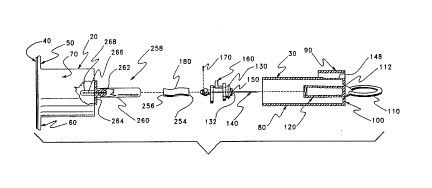
Reference is now made to Figure 1 wherein an embodiment according to the
invention of a blood draw device 10 is seen. As seen in Figure 1. device 10 comprises
a barrel section 20 and a needle colltaimllent section 30. In a completely assembled
device, section 20 is securely affixed to section 30 along circular line 32 to provide
protection for contents of the device from environmental damage and cont~min~tion.
Barrel section 20 comprises a planar seal 40 and a pair of left and right ear orhandle parts, ~lP~ign~teA 50 and 60, respectively, and a hollow barrel 70. Planar seal 40
is adhesively attached to barrel section 20 within a plane area defined by continuous line
72 such that the hollow of barrel 70 is m~int~ined in a sterile condition prior to use. To
use device 10, seal 40 is manually removed. Of course, a different kind of seal may be
used, such as a snap-on part which may be molded as a tether-attached part of section 20.
The snap-on part is not shown, but production of such parts is well known in the art. A
more detailed description of the internal parts of barrel 70 is provided hereafter.
Needle collL~il"llent section 30 comprises an elongated tube 80t a flap 90, a
proximally facing front face plate 100 and a pull-ring 1 10. Pull-ring 110 is separable
~ from front face plate 100 at a frangibly detachable segment 112~ which is described in
more detail hereafter.
Steps related to the use of device 10 are seen in Figures ~-4. In Figure 2, pull-ring
110 has been detached from front face plate 100. Det~ehment of segment 112 produces
a ragged collar 1 14. As pull-ring 1 10 is advanced from face plate 100, a needle cover
CA 0220~831 1997-0~-21
WO 96/21483 PCTIUS9SI16665
14
1207 which is firmly affixed and integrally molded with pull-ring 110, appears through
a hole created by removal of collar 114. Once pull-ring 110 is fully extended, a yoke 130
snaps into place about the hole produced by removal of collar 1 14. The structure of yoke
130 and its related parts are disclosed in more detail hereafter.
A next step is to remove seal 40 from barrel section 20. Figure 3 illustrates seal
40 in the process of being removed. In a next step, pull-ring and needle cover 120 are
removed from device 10. Needle cover 120 is preferably attached to a hub 132 by a
rotatably detachable coupler, such as by a threaded or bayonet type connector. In any
event, the coupling attachment between hub 132 and cover 120 must be able to support
10 a pull force of at least as great as a retarding force imposed in the opposite direction by
a retracting mech~ni.~m which is energized by the pull extending cover 120 untilengagement of yoke 130. As seen in Figure 3, a hollow medical needle 140 is bared
upon removal of cover 120.
As seen in Figure 4, flap 90 comprises a living hinge ~ hment 142 to elongated
15 tube 80. Flap 90 also comprises a hook latch 144 which is normally engaged in a groove
146 proximally disposed in tube 80. Located in flap 90, when disposed in groove 146,
is a deformable area 148 of tube 80. While flap 90 is disposed and latched into groove
146, area 148 is fully protected from any deformation. Thus, during a medical blood
draw procedure, flap 90 is latched into groove 146. Once blood acquisition has been
20 completed, flap 90 is rotated by action of a single digit after which needle 140 may be
retracted by depressing area 148. Retraction places needle 140 safely inside tube 80. The
only access inside tube 80 and needle 140 is a hole 150 in hub 132 which is the
essentially the same diameter as the cross sectional diameter of needle 140. Further. as
is explained later, needle 140 is securely held well away from hole 150. Retraction
25 mech~ni~m.~ for needle 140 are described in detail hereafter.
Also seen in Figure 4 is a snap-on cover 151 affixed by a tether 152 to handle 60.
Cover 151 is an alternative embodiment to seal 40. Cover 151 has the advantage of not
requiring a cover part to be made separately from barrel section 20. However. to provide
assurance that cover 151 has not been opened previous to a procedure to which device
30 10 is uniquely dedicated. an additional seal, such as a shrink wrap about exterior edges
CA 0220~831 1997-0~-21
WO 96J21483 PCT/US95116665
of cover 151 and related parts of handles 50 and 60 and tube 80 should be used. The
m~king of parts attached by tether is well known in the art.
Reference is now made to Figure 6 wherein an exploded view of one embodiment
of device 10 comprises a needle co..f ~ ent section 30, a needle/hub part 160, a valve
S disk 170, an elastic tube 180 and barrel section 20. Attention is first drawn to needle/hub
part 160, which is shown m~gnified for more clarity of details in Figures 7-9.
Part 160 compri~es medical needle 140? a fore part 190 proximal to the sharp endof needle 140, a central part 192, and an aft part 194. Normally, unseen extensions of
needle 140 throughpart 160 is indicated by double dashed lines 196 and 198 for clarity
10 of the extent of needle 140 passage through part 160. Fore part 190 comprises yoke 130,
hub 132, annular groove 200, annular stop 202, and elbow shaped extension 204 which
comprises an outwardly exten~lin~; part 206. Central part 192 comprises a frangible
bridge 208 and a support 210. Aft part 194 comprises a short shaft 212 and a tube hub
214. Part 160 is preferably molded as a single part with end-to-end continuity between
15 parts 190, 192 and 194. Aft part 160 is firmly and securely affixed to needle 140, while
fore part 190 is only slidably affixed and otherwise free to move along needle 140 when
bridge 208 is franged. Aft part 160 may be affixed adhesively by methods which are well
known in the art.
Hub 132 comprises a releasable connector component which may be in the form
20 of a threaded surface 216 as seen in Figures 7-9. Yoke 130 comprises a sloped annular
face 218 and atransverse l~tching surface ring 220 distal to and juxtaposed to face 218.
Groove 200 is interposed between and contiguous with ring 220 and stop 202. The
function and use of yoke 130, groove 200 and stop 202 are described in detail hereafter.
As best seen in Figure 7, an extension 204 protrudes distally from stop 202 via
25 a lateral bar 222 to an elbow 224 where extension 204 makes an orthogonal bend to form
upward and outwardly extenclin~ part 206. Bridge 208 is a part which is narrow in both
transverse dimensions to govern the degree of pressure required to frange bridge 208
from extending part 204. One of the surprising aspects of the instant invention is the
force which may be placed upon bridge 208 when pulling against a force retaining30 memory element used in retracting needle 140 without breaking bridge 208 away from
extension 204. Clearly. if even a nominal torque is place upon bridge 208 during a pull,
CA 0220~s3l l997-0~-2l
WO 96121483 PCrlUS95/16665
16
bridge 208 might break. Close tolerances should be m~int~ined between needle 140 and
fore part 190 to reduce and keep such torque at a level which does not cause bridge 208
to break while needle 140 is being pulled forward. The method for achieving close
tolerances between needle 140 and fore part 190 is disclosed hereafter.
Bridge 208 is contiguous with a support 210. Shaft 212 is medially disposed
about needle 140 and distally connected to support 210. Tube hub 214~ connected to
shaft 212, provides a valve leaflet containment basket 226, wherein a one-way valve
leaflet may be placed and trapped by a tube mounted on hub 214. Basket 226 is better
seen in Figure 10. Basket 226 comprises a slot formed by a distal facing side 228 and a
10 proximal facing side 230, the two sides being connected by a bottom plate 232 and two
side members 234 and 236.
Side 228 is a smooth planar face comprising a non-protruding blunt end 238 of
needle 140. Also shown in Figure 10 is a valve leaflet disk 240. Disk 240 is made of
compliant synthetic resinous material which, under pressure~ deforms to seal end 238 of
15 needle 140 against regurgitant flow when pressure downstream from needle 140 is
greater than upstream pressure. This seal is very important to contain blood within
needle 140 upon retraction of needle 140. To assure a low resistance to flow from needle
140, disk 240 comprises a plurality of raised feet which space the distal side of valve disk
240 away from side 230. That spacing and various cuts~ designated 242~ 244, 246 and
20 248 in distal end 250 of aft part 194 provide a low resistance pathway for effluent flow
from a patient.
Care should be taken such that the diameter~ design~ted by A arrows, of disk 240is less than the sum of distances indicated by arrows B and C~ but greater than B plus the
diameter of needle end 238 to assure that regurgitant flow is always stopped. However~
25 disk 240 should not be inadvertently held in an open condition by a tube stretched over
hub 214.
Another embodiment of a one-way valve is seen in Figure lOA. If hub 214 is
made of sufficiently resilient and compliant materiaL a leaflet valve may be integrally
molded on the distal end of the hub. In the embodiment of Figure lOA~ a thin planar
30 wafer 252 is integrally connected to a hub 214' (which is otherwise similar to hub 214)
CA 0220~831 1997-0~-21
WO 96/21483 PCT/US95/16665
by a living hinge to curtail proximal flow through needle 140 at end 238 while being
permissive to distal effluent flow.
~ In the embodiment seen in Figure 6, retractive force is provided by a stretched
tube. For this purpose, tube 180 is cut to a predetermined length allowing for
displacement about a proximal and a distal hub and for a length of the tube which
stretches when device 10 is cocked as needle 140 is pulled outward for use. Tube 180
comprises a proximal end 254 and a distal end 256. Tube 180 may be made from anyelastic material which is effectively inert to blood and which can provide a return force
sufficient to retract a needle directly from a patient into safe containment. (An elastic
force in the range of two to four pounds is recommen-l~cl although it has been found that
a return force in the range of one pound is adequate to remove needle 140 from a patient
and retract it into a housing.)
The tube should preferably be capable of being stretched at least a length of four
times its resting length. However, the ~;u~ lLly ~lcf~ ,d m~tçrizll is latex. Note that a
needle of one inch in length should require a tube not greater in length than about one-
half inch.
Barrel section 20 comprises a plurality of internally disposed parts, generally
clesign~ted 258. Parts 258 comprise an elongated stabilizing key 260, a distal tube hub
262, an assembly plate 264, a rear delivery needle 266? and a needle cover 268.
Stabilizing key 260 is an elongated rod which stretches from assembly plate 264
to beyond stop 202 when device 10 is assembled and tube 180 is relaxed. Hub 262 is
formed about needle 266 to provide a piercing entry to a low pressure collection tube ~not
shown) such as a VACUTAINER~ nllf~rtnred and distributed by Becton Dickinson
of Franklin Lakes, New Jersey.) As is standard practice in an apparatus which is used to
provide entry to low pressure collection tubes, a pierceable needle cover 268 is provided
to deter leakage as collection tubes are replaced.
Figures 6, 11, 12, 13 and 14 demonstrate simplicity of assembly of device 10.
Figure 6 is representative of parts in a prç~çmhled configuration. Step one in assembly
comprises insertion of valve disk 170 into valve cont~inment basket 226 as seen in Figure
11. Note that step one is not required when a valve leaflet such as a valve formed bv
wafer 252 is an integral part of tube hub 214'.
CA 0220~831 1997-0~-21
WO 96/21483 PCT/US95/16665
18
Attachment of tube 180 to hub 214 (or hub 214' in the case of the embodiment
seen in Figure 10A) is seen in Figure 12. To assure that tube 180 iS securely affixed to
hub 214 (or 214'), it is recommended that an adhesive be applied to a proximal portion
of hub 214 (or 214') immediately before tube 180 ~ chment. A suitable adhesive
material should be used and care should be taken to assure that no in~lopliate blood
reactive material is allowed to contact areas where blood may flow. One adhesive which
has provided satisfactory adhesion in models of the invention which have been reduced
to practice is Duro Super Glue, manufactured and distributed by Loctite Corporation,
Cleveland, Ohio 44128, commonly known as Super Glue. although other adhesive
10 materials known in the art may also be used within the scope of the invention. All such
adhesives should be qualified to be compatible with use in a medical application.
Completion of a fluid flow path from needle 140 is seen in Figure 13. Tube 180
is connected on distal end 256 to hub 262. At the same time stabilizing key 260 is
engaged in a locking slot 270 (See Figure 14A) disposed in armular stop 202. Key 260
15 is formed to slide laterally into and out of slot 270 and fit snugly therein when tube 180
is relaxed (i.e. during assembly). In this manner, no undue torque or rotational stress is
placed upon frangible bridge 208 during assembly. To provide a pathway for key 260
past support 210, a material relieving flat 272 is formed along the plane of travel of key
260 in support 210.
As a next step~ needle contaimllent section 30 is disposed about the assembled
parts. Needle cover 120 comprises a female connecting segment 774 which is
complementary to the male connector provided by hub 216. Cover 120 is preferablyaffixed by rotating section 30 relative to hub 216 although press-on connections which
can withstand pull forces exerted by an elongating tube or spring or the like may also be
75 used. As needle cover 120 is connected to hub 216~ tube 80 of section 30 engages
assembly plate 264. Tube 80 is securely affixed to assembly plate 264 by adhesive or
ultrasonic welding processes which are well known in the art of plastics assembly. In this
manner a union is provided to protect needle 140. As such sections 20 and 30 in
combination provide a housing for needle 140 which may be used without additional
30 packaging for transport.
CA 0220~83l l997-0~-2l
W O96/21483 PCT~US95/1666
Attention is now drawn to front face plate 100 of section 30. Face plate 100
compri~e~ a proximal surface 276 and a substantially distal planar surface 278. Disposed
in surface 278iS an armular groove 280. Groove 280 completely encircles the area where
cover 120 integrally connects to plate 100 and a ring hub 282 which is integral with the
5 proximal end of cover 120. Hub 282 also integrally connects ring 110 to section 130.
Groove 280 is of sufficient depth in plate 100 to permit facile frangible separation by a
positive tug, twist or pull on ring 110 while retaining sufficient m~teri~l to provide a
sealed container and a sturdy and safe transport container. Products having such seals
are available in commerce.
Frangibly separating ring 110 and cover 120 from section 30, as seen in Figure
2. causes tube 180 to be stretched between separating hubs 214 and 262 as is best seen
in Figure 15. Note that needle hub part 160 and, in particular~ locking slot 270 are pulled
away from key 260 by the same action. For this reason, it is advisable to make groove
280 and cover 120 somewhat asymmetric to minimi~ rotation during tube extension.One of the material attributes which permits tube 180 to be used to store energy to retract
needle 140 and to act as a pathway for fluid communication between needle 140 and
needle 266 is that the internal lumen of a tube remains patent when stretched. The
diameter of the lumen is reduced but not closed as the tube elongates.
When ring 110 and cover 120 are separated from section 30 by franging plate 100
at groove 280, an annular hole 284 is created in plate 100. As seen in Figure 14, when
needle/hub part 160 is pulled proximally, cover 120 and then yoke 130 are pulled through
hole 284. The sl~nting annular surface 218 of yoke 130 as best seen in Figures 7-9~
comprises a proximal diameter which is smaller than the diameter of hole 284 and a distal
diameter which is larger than hole 284. However~ the distal diameter is such that yoke
130 passes through hole 284 due to the "give" of m~t~ l from which section 30 is made.
Groove 200 has a width which permits plate 100 to be engaged therein after yoke 130 is
pulled through hole 284. The proximal face of stop 202 has a diameter which is greater
than hole 284 causing part 160 to be firmly affixed to plate 100 when yoke 130 passes
through hole 284, as seen in Figure 14.
Once the procedure involving needle 140 is completed~ and preferably while
needle 140 is yet disposed in a patient's blood vessel, needle 140 is automaticall~
CA 0220~831 1997-0~-21
WO 96/Z1483 PCT/US9~/16665
retracted. The retraction process involves (1) hingeably relocating protective flap 90 (as
seen in Figure 4) and (2) applying ples~ upon part 206 through area 148 of tube 80 to
frangibly separate fore part 190 from aft part 192 by breaking bridge 208 of needle/hub
part 160.
Flap 90 is commonly released from attachment to tube 80 at groove 146 by
inserting a thumb or finger under a portion of flap 90 and lifting. Bridge 208 is broken
by applying pressure, preferably between a thumb and forefinger, in the direction of
arrows 284 and 286. Franging forces (i.e. shear forces) are thus applied through area 148
to part 206 and an interior portion of tube 80 to support 210. Note that substantially all
other forces applied to bridge 208 are those of tension caused by longitudinal stretching
of tube 180. For this reason, bridge 208 comprises a geometric shape which is conducive
to breaking when imposed upon by shear forces, but capable of withstanding largeamounts of tension.
One of the major reasons that substantially all of the forces placed upon bridge208 during extension of a retractive mech~ni~m is a close tolerance held between needle
140 and fore part 190. As mentioned previously, part 190 is made to be free of needle
140 such that it can slide thereon. To m~intz~in the tight tolerance and to provide an
inexpensive method for manufacture of part 160, needle/hub part 160 is preferably
molded as a unit about needle 140. Part 160 is preferably injection molded.
To permit fore part 190 to be molded about needle 140, yet remain slidably free,a thin coat of mold release is applied about needle 140 prior to molding. By applying a
coat of mold release 288 in an area wherefore part 190 is molded. fore part 190 remains
only slidably attached to needle 140. Of course, at the distal end 290 of needle. aft part
194 is firmly and securely affixed by the molding process causing needle 140 to be
retracted when tube 140, attached to aft part 194, is permitted to contract. Note that when
needle 140 is retracted through yoke 130 and hub 132, the only access into tube 80 is
through hole 150 which has substantially the same diameter as needle 140. Of course,
once needle 140 is retracted, it is irretrievably held inside tube 80 by a relaxed tube 180.
Except for needle 140~ which is made of medical grade steel, needle/hub part 160is made from a moldable material having sufficient tensile strength to withstand pull
pressures of device 10, yet be facilely separated at bridge 208. As such, part 160 is
CA 0220~831 1997-0~-21
WO 96121483 PCT/US95~16665
preferably made of a synthetic resinous material, such as polyurethane, polypropylene
or polyethylene. For an experimental device, the synthetic resinous material used was
polyurethane sold as Quik Cast distributed by TAP Plastics, Dublin, California 94568.
However, many commercially available materials may be used within the scope of the
5 invention.
Barrel section 20 is likewise preferably made from synthetic resinous material.
Barrel section 20 is also preferably molded about rear delivery needle 266. The same
material which is used in commercially available barrels used with vacuum based blood
drawing tubes (e.g. VACUTAINERS(~) may be used. Needle cover 268 may be one of
10 the same as VACUTAINER(~) barrel needle covers now commonly used.
Needle col~t~ill",ent section 30 is preferably made by a single molded process.
Mold m:~teri~l should be selected such that it provides sufficient m~teri~l strength to
engage and hold the hub 132 connection through the pull process. sufficiently flexible
when made as a thin membrane to permit distortion sufficient to break bridge 208, and
15 frangibility for facile opening as at groove 280. The m~teri~l iS preferably a synthetic
resinous material and may be polyethylene, although other materials meeting flexibility,
medical compatibility and strength requirements may be used.
Reference is now made to Figures 16-20 which relate to another embodiment of
the invention. This embodiment is similar to the embodiment seen in Figures 6-14 in
20 general forrn and function, but does not depend upon a frangible part to release and
rekact the needle. As seen in Figure 16, a needle/hub assembly 300 comprises two parts~
designated fore-part 302 and aft-part 304, which are formed about a needle 140. Parts
302 and 304 may be molded about needle 140 simultaneously. Part 302 is preferably
molded about a segment of needle 140 to which a mold release has been applied as25 earlierdescribed. (See Figure 5.)
Fore-part 302 comprises a central body 306 and a pair of outwardly extending
wings or arms, individually ~le~ign~t~l 308 and 310. Each arm 308~310 is connected to
central body 306 by a biased hinge 312 and 314, respectively. The biasing of hinges 312
and 314 is preferably formed as a part of the molding process. Such hinges are well
30 known in the art (as an exarnple, note the hinges on telephone connectors). Each arm
308~310 is biased to extend outwardly from central body 306 a predetermined distance.
CA 0220~831 1997-0~-21
WO 96/21483 PCI'IUS95/16665
Disposed at the outer end 318,320 of each arm 308,310, respectively, is an inwardly
projecting l~tching extremity 322,324.
Central body 306 comprises a cover connecting hub 132', which is similar in formand function to hub 132. A portion 316 is disposed distal to hub 132', where hinges 312
5 and 314 are attached.
Aft-part 304 comprises a central boLY part 326, a pair of outwardly exten-ling and
biased wings or arms 328 and 330 and a tube hub 332. Wing 330 comprises an inwardly
projecting strut 334, which ends at a clamping face 336. In opposing fashion. wing 328
comprises an inwardly projecting jaw 338. Function and use of the various parts of fore-
10 part 302 and aft-part 304 are disclosed in detail hereafter.
As mentioned earlier, fore-part 302 is preferably molded about needle 140? but
not attached thereto, except by the natural engagement provided by materially
surrounding the circumference of a portion of the needle. This permits fore-part 302 to
be rotated 90~ and moved into linkable proximity with aft-part 304 as seen in Figure 17.
The parts content in this second embodiment of blood draw device 10 is best seenin Figure 21. This second embodiment comprises a barrel section 20', tube 180, needle
hub assembly 300 and needle co~ ."~nt section 30.
Barrel section 20' is substantially the same as barrel section 20 except for thesubstitution of a guide-catch cylinder 340 integrally and medially disposed on a fore
20 portion of barrel section 20' rather than a stabilizing key similarly disposed upon barrel
section 20.
Guide-catch cylinder 340 is best seen in Figure 20. As seen therein. barrel 20'
comprises barrel 70, a substantially closed fore face 342 of barrel 70, distal needle hub
262 providing access to needle 266, and guide-catch cylinder 340. Guide-catch cylinder
25 340 is medially disposed upon face 342 and extends in elongated fashion in line with
needle 140 (not seen in Figure 20). Hub 262 is medially disposed inside cylinder 340
along the same line.
Cylinder 340 comprises a plurality of slots which provide relief for outwardly
biased members of parts 302 and 304, travel guide for assembly 300 and catch stops
30 which selectively m~int~in parts of assembly 300 in a proximal position while the needle
CA 0220~831 1997-0~-21
WO 96121483 PCT/17S9S/16665
is in use. A first slot 346, disposed to act as a guide, extends the length of cylinder 340.
In this embodiment, device 10 is assembled to dispose a portion of wing 330 in slot 346.
- Disposed at its distal end, cylinder 340 comprises a second slot 348 offset at 90~
~om slot 346 and having a length which is adequate for relief from co~ ession of wing
308, when assembly 300 is distally disposed before use. Likewise, cylinder 340
compri~?c a third slot 350 similar to slot 348 and juxtaposed 180~, therefrom, to provide
relief from compression of wing 310. A fourth slot 352 of cylinder 340 is distally
disposed 180~ from slot 346 and provides before-use relief from compression for wing
328. If an outwardly biasing material is used in the m~nllf~r.tllre of assembly 300 which
does not take a set after time between assembly and use~ it is not necessar,v to provide
slots 348, 350 and 352.
Cylinder 340 provides openings for four slots at its proximal end 353, i.e., slots
346,354,356 and 358. As mentioned earlier, slot 346 provides a guide for assembly 300
by cont~inment of wing 300. Longitudinally slots 354 and 356 are respectively aligned
with slots 348 and 350. Slot 354 comprises a c~tçhing edge 360 for end 318 of wing 308,
while slot 356 comprises a czltrhing edge 362 for end 320 of wing 310. Slot 358 is
aligned with slot 352 and provides a c~tching edge 364 for wing 328, as is described in
detail hereafter. Each slot has a depth such that in combination latch portions of wings
308, 310 and 328 occur substantially simultaneously.
The l~t(~hin~ operation of the elements of assembly 300 is best seen in Figures 18
and 19. Each of Figures 18 and 19 are divided by dashed lines into three sections (A~ B
and C) to demonstrate operation of fore-part 302 and aft-part 304 of assembly 300 at
different positions along the length of cylinder 340. Note that wings 328 and 330 are
vertically disposed in Figure 18. Wings 308 and 310 are vertically oriented in Figure 19
as parts of assembly 300 in Figure 19 are rotated by 90~ relative to parts in Figure 18.
It is particularly important to note that wing 328~ as seen in Figure 18A and 18C~
extends superiorly from central body part 326 along a line 366 to pivot arcuately upward
at arc 368 to join a superior line 370. Further~ line 370 ends at a latch point 372. From
latch point 372. the shape of wing 328 is further defined by an inwardly progressing line
374 and an acutely connected line 376 which~ in combination~ demarcate jaw 338.
CA 02205831 1997-05-21
WO 96/21483 PCI~/US95/16665
, 24
As seen in Figure 18A. wherein assembly 300 is residing distally within c,vlinder
340 and tube 80. wing 330 is free to move in the longitudinal direction of needle 140
guided by slot i l6. In the sarne assembly 300 position. wing 328 is disposed in an
uncoln~lessed or relaxed state within slot 352. When assembly 300 is pulled proximally
5 to a cocked and useful state as seen in Figure 18C, assembly 300 passes through an
interTn~ t~ state seen in Figure 18B. As assembly 300 is moved proximally from the
state seen in Figure 18A, the forrn of wing 378 forrned along arcuate line 368 perrnits
wi'ng i28 to be collapsed, such that line 370 of wing 328 coincides ~ith the cylindrical
inner surface of c,vlinder 340. In this manner, the aft-part 304 of assembl,v 300 is facilely
10 allowed to move through cylinder 340.
Note that compression of wing 328 as seen in Figure 18B causes jaw ii8 to
col~ es~i~elv pinch tube 140 thereb,v stopping any flow of liquid therethrough while
wino 328 is bet ~een slots 357 and 358. Moving assembly 300 proximall,v to the position
seen in Figure 18C permits w-ing 328 to be once more relieved as it is biased to enter slot
l S 358. Once there. a latch formed at latch point 372 and along line 374 is caught by edge
364, firml,v ret~ining assembly 300 with tube 140 in a stretched condition.
Referring now to Figure 19, device 10 has been rotated 90~ clockwise relative toa view of the needle 140 end of the device. In Figure 19, wings 308 and 310 are
vertically oriented. Each arm 308,310 resides in a non-co,~ ;,st:d state in slots i48 and
20 350, re.~ye~ ely. Arm 308 comprises an arcuate surface 378, similar to the wing 328
arcuate surface along line 368, which provides a facile release from slot 348. Arm 310
comprises a similar surface 380 for facile release from slot 350.
As assembly 300 is pulled proximally from the state seen in Figure l9A to the
state seen in Figure l9B, arms 308 and 310 are compressed inwardly. Each arm 308 and
310 comprises a l~tt hing foot, respecti~,-ely desi~nz-red 382 and 384, which engages and
grips a distal annular surface 386 of central body 3~6. In this manner, fore-part 302 is
releasibly adjoined to aft-part 304 ~hile assembl,v 300 is pulled forward to a coclced
position. In its most pro~imal position. arms 308 and i 10 are outwardlv biased into slots
i54 and 356. respectivel,v. In this position. feet 382 and 384 catch a_ainst edges i60 and
30 i67 to form apermanent latchthereat. Note that outward biasing of arrns iO8 and ilO
CA 02205831 1997-05-21
WO 96121483 PCT/US9S/16665
release the crasp of feet 382 and 384 a~ainst surface 386, therebv releasing the ~rip of
aft-part 304 bv fore-part 302.
When the grip of aft-part 304 is so released, needle 140 is relieved of proximalcontaimnent in tube 80 when aft-part 304 is triggered to a released state to be distally
displaced by contraction of tube 180. Referring once more to Figure 18C, aft-part 304
is rçleased from a cocked state by d~rea~ o area 148 in the direction of arrow 38~.
Such depression forces wing 3278 inward until the part of wing 328 along line 374 and
latch point 372 clears edge 364. Contraction of elastic tube 180 retracts aft-part 304 and
needle 140. to which the aft-part is securely affLxed. into the distal section of tube 80 seen
10 in Fi~ure 1 ~A. Fore-part 302 remains proximal in tube 80 to effectively plug the hole
formed bv removal of hub 282 and collar 11~. Note that fore-part 302 comprises athreaded hub 132', similar to hub 132.
Reference is now made to Fi_ure 21 where an e~ploded view of parts which are
comprised in the alternate embodiment seen in Figures 16-20. The alternate embodiment
1~ parts comprise barrel section 20', tube 180, needle hub assembly 300 and needle
cont~inmçnt section 30.
Assembly of the parts seen in Figure 21 into a complete needle retracting device10', which is functionally equivalent to device 10, involves the following steps:
ff~xin_ tube 180 to hub 332;
2. Biasing wings 308, 310 and 328 inwardly and sliding assembly into
cylinder 340 for engagement with slots 348, 350 and 352, respectively;
3. .~ffixing tube 180 to hub 262. Note that access to hub 262 is provided
through slot 346;
4. Laterally displacing section 30 such that the thre~ded connecting segment
2~ 274 of needle cover 170 engages hub 132';
5. Rotating section 30 to affi~c hub 132' to needle cover 120 (assembly 300
is reskained from rotating because wing 330 is disposed in slot 346 both
during assembly and cocking procedures;
6. Affi:cin~ section 30 to section 20', preferably by application of adhesivesor by ultrasonic welding to forrn a hermeticallv se~led package about
needle 140.
CA 0220~831 1997-0~-21
WO 96t21483 PCT/US95116665
26
Reference is now made to Figures 2'~ and 23 where a catheter insertion apparatus400, another embodiment of the invention. is seen. A closed, transport compatible
packa_e of a~alal-ls 400 is seen in Figure 22. Exteriorly, ap~aldl-ls 400 is seen to
comprise a pull ring 110' affi:~ed to and integral with a front face plate 100', which is
5 similar to face plate 100. Face plate 100' is integral with a tube 80' which is also similar
in form and function to tube 80. Face plate 100' also comprises an annular frangible
segment 112' which permits ring 110' and a collar portion 114' of plate 100' to be
frangibly s~ L~d from plate 100' when pulling a needle assembly pro~cimally from tube
80' for use.
Tube 80' comprises a flap 90' similar in form and function to flap 90, which is
releasibly affLYed to a groove 146' and on an opposite end attached by a living hinge 14'"
to tube 80'. Tube 80' is elon~ated to fully contain a needle 140' used in catheter insertion
and a needle draw mech~ni~m 402, as seen in Figure 23.
At its distal end, tube 80' comprises an annular raised section 404, which acts as
15 a handle during the needle pulling procedure. Further, app,1 l d~US 400 comprises a distal
plate 406 which is securely affi~ed at the distal end 408 of tube 80' to enclose and
hermetically seal needle 140' and withdrawal mech~ni~m 402 inside tube 80'.
Withdrawal mech~ni~m 402 comprises a needle/hub part 160', which is similar
to part 160 in form and function. Basic ways in which part 160' departs from the form
20 of part 160 is found at the proximal and distal seFgments of part 160'. Proximally, part
160' comprises a secondary connection 412 for a tr~n~c~lt~neous catheter 410.
Such catheters and catheter connections are well known in the transcutaneous
catheter art. Also needles used with transcutaneous catheters are readily available. A
common source is Becton Dickinson Corporation of Franklin Lakes, New Jersey 07417-
'~5 1883. A current source for such catheters is Abbot Hospitals, Inc., North Chicago, Ill.60064. The material from which tube 80' and plate 406 is made is similar to materials
prescribed for tube 80.
Distally part 160' compnses a connection 414 whereby a return ener~ y storing
component 416 is affi~ced to a hub ~18 portion of part 160'. As seen in Fi~ure '~3t part
30 160' comprises c~theter needle 140'. a fore part 190' pro~imal to the sharp end of needle
140', a central part 19~', and an aft part 194'. With the e:~ceptions of pro:cimal and distal
CA 02205831 1997-05-21
WO 96t'~1483 PCT/US9~1666
27
connections of mech~nicm 40~. parts 190', 197' and 194' are substantiall,v the sarne in
form and function to parts 190. 192 and 194. A bridge part 208' and upwardly ~t~n~iin~
part 706', each being respectively similar in form and function to bridge ~08 and part ~06,
are similarly inwardly disposed for compressible access via a depressible area 148' of
5 tube 80'.
Mar~edly different. although within the scope of the invention is return energ-
storinlJ component 416. Component 416 comrTiCPc a plurality of piston head parts ~20.
42'7 and 424, which communicate with an innèr wall 426 of tube 80' to effectively pull
and retain a vacuum as the mech~ni~m is moved pro~imally. The vacuum contained in
10 tube 80' provides the force which retracts needle 140' when bridge '208' is frangibly
broken. To provide an adequate retraction force. parts 420. 47~ and 424 must create a
differeniial force of at least four pounds to overcome forces of stiction in both the needle
and other retracting merh~nicmc For aE.y~dLlls 400 to have substantiallv universal use.
a minimum atmospheric pressure of ten pounds per square inch is assumed. For a
15 minimllm pressure of four pounds realized from an atmospheric pressure of ten pounds
per square inch. each part 420.427 and 424 must have a minimum area of four tenths of
a square inch. As parts 420, 1~ and 424 are ~c.~enti~lly circular planes. their diame~er
must be a minimllm of .36 inches (.9 centimeters).
Parts 120,42~ and 424 are securely affIxed to a medially disposed piston hub 428.
20 which is in turn likewise affixed to me~h~nism 416 via aft part 194'. As indicated bv
dashed lines 430, needle 140' communicates with hub 428 via part 194. Hub 428 is a
hollow vessel which is completely sealed, e~cept for a gas communicating plug 43'~
disposed proximal from part 424.
Plug 432 is made from a hydrophobic material which is permissi~ e to passage of
75 gas (air). but retards flow of water based liquids (such as blood). The preferred material
is Gorete~c, a m~tt~ l available from W. L. Gore Compan,v, Arizona, USA. Plu~ 432 is
securely :~ffixed to hub 428 to provide a pathwav for gas to relieve pressure as blood is
communicated into hub 4~8 throu(~h needle 140'.
Hub 428 is made from either translucent or transp~rent materials through which
30 blood mav be seen. Thus. by providing the pathway from needle 140' into hub 4~8 and
permitting air to escape from hub 428 as influent blood arrives. hub 428 provides 2
CA 0220~831 1997-0~-21
wo 96/21483 PCr/US95116665
~8
visually determin~hle blood "flash", which is comrnonlv used to ascertain emry of needle
140' into a blood vessel.
To use a~pa~Lus 400. ring 110' and collar 114' are fran~ibly separ~ted from plate
100'. Needle cover 120', needle 140', and catheter 410 are pulled from tube 80', until
S mef~h~ni~m 40~ is firmly attached to plate 100'. Bv this action a vacuurn is created in the
portion of tube 80' which is distal to part 420. Cover 1'70' is removed and needle 140' and
catheter 410 are transculaneously inserted into a patient following good medicalpr~ctices. When needle 140' enters a blood vessel. blood is communicated to hub 428
throuPh which a blood "flash" communicates to the ~ nriing technician that the vessel
10 has been entered. At this poinL flap 90' is lifted to provide access to area 148'. A portion
of area 148' is depressed to frangibly break brid_e 208', which releases the aft portion
194' of mechanism 402 to be retracted bv force stored via parts 420, 422 and 474 in
cooperation with tube 80'. Needle 140' is thereby ~ithdrawn. Note that the only pathwav
through blood may be communicated upon withdrawal of needle 140' is into tube 80'.
15 This limitation upon needle withdrawal is a definite advantage over non-self-retracting
needle systems ~ lLly in use. Under ap~lupl;ately controlled conditions, catheter 410
is removed for ~t~chment of other medical devices.
Reference is now made to Figures 24 and 25 wherein a standard cornmercially
available 3 cc syringe 500 is seen in Figure 24 and a self-retracting medical needle
20 assembly 510 is seen in Figure 25. Syringe 500 comprises a male luer fitting 512 and a
female luer lock connector 514 disposed at an end of an elongated svringe barrel 516.
Male fitting 512 comprises a fluid flow lumen 518. through which fluid is comrnunicated
between barrel 516 and a medical needle.
Assembly 510 comprises a housing 520. a female luer lock connector 522 and a
25 needle cover 524 e~ten~ling outward from housing 520 at an end of housing 520. which
is distal from luer lock connector 5'''. Cover 524 comprises a thinned section 526 and
an enlarged end 528 which. in combination, provide a section which may be easilygrasped between a thumb and forefinger to pull cover 574 from housing 570.
Steps involved in usin~ assembly 510 are best seen in Figures 26A-D. An "off-
30 the-shelf" embodiment of assembly 510, with an aft portion covered by a cap 530 is seen
in Figure 26A. Cap 530 preferably comprises a male luer lock thread similar to female
CA 02205831 1997-05-21
WO 96/21483 PCT/rJS95~16665
. 29
luer locl~ connector 514 for secure ~t~chment to luer loclc connector 522 of housing 520.
In place for transport, cap 530 also is frangibly connected to housing 510, preferably by
a connection process known in the plastics molding ar~ as heat staking. Similarly, cover
524 is pre~erably frangibly connected to housing 520 by heat staking.
Af~er assembly 510 is connected to a syringe, seen in part by a section of female
Iuer lock connector 51~ in Figure 26B, cover 524 and a medical needle 540 (seen in
Figure 26C) are pulled from housing 510. Cover 524 is preferablv frangibly separated
from housing 510 to permit cover 524 and needle 540 to be so e~tended.
As seen in Figure 26C, cover 524 is removed (preferably bv a quarter-turn hvist)10 to e~pose medical needle 540. Also e~cposed is a first hub 550 which rides upon needle
540, but which is slidably free from needle 5~0 when needle 540 is retracted.
After a medical procedure, medical needle 540 is retracted. bv releasin~ a latchfrom a catch (disclosed in detail hereafter), back into housing 510. ~ote that lumen 552~
through which needle 540 retractively travels, is the only opening which remains at the
15 fore-end of housing 510 upon needle retraction. Following retraction? medical needle
540 is comple~ely and safely contained inside housing 510, therebv permitting simple
procedures for safe disposal.
Reference is now made to Figure 27 in which one embodiment of syringe needle
assembly 510 is seen in cross section. greatly m~gnified. A syringe 500 is affixed to
20 assembly 510 by a female luer lock connector 514. As described earlier, female
connector 52~ is threaded into luer lock connector 514 to firmly, but releasibly, affix
assembly 510 to syringe 500.
In addition to cover 524 and housing 520, assembly 510 comprises a medical
needle hub assembly 560, an elastic tube member 570 and an inner housing member 580.
25 As disclosed heretofore, cover 524 comprises a thinned section 526 which provides for
facilely gripping cover 524 to pull it and needle 540 from housing 520. Cover 524 also
comprises an elongated hollow barrel section 58 ~ in which needle 5~0 is protectively
enclosed prior to use. At an end 584 which is distally disposed from thinned section 526.
cover 5'4 comprises a coupler 58 l which releasibly attaches to hub 550. Such
~0 attachment is preferably thre~ded.
CA 02205831 1997-05-21
WO 96121483 PCl~/US9S/~666~S
Housing 520 compnses an elongated cylindrically shaped barrel 586 and orifice
58~ disposed at a needle e:~it and reentry end 590 of barrel 586. At an end 592, which
is distal from end 590, barrel ~86 comprises a blunt transverse termination. Disposed
near the e~cit and reentrv end 590 is a deformable area 148' (similar in form and function
S to area 148. described heretofore). To accomplish the function of area 148', housing 520,
cover 5?4 and inner housing member ~80 are made from a pliable synthetic material, an
e~cample of which is polyprop~ lene. Though not seen in Figures 25-28, one should
~nflers~ncl that a flap similar to flap 90 may be added to housing 570 to protect area 148'
from being inadvertently prematurely depressed.
Medical needle hub assembly 560 comr~ Ps medical needle 5~0, a fore hub part
;02' and an aft hub part 304'. Hub parts 302' and 304' are similar in form and function
to parts 302 and 304, respectively" and are therefore denoted by primes of the e~rlier
narned hub parts. Parts 302' and 304' comprise essentially all of the fe~tures of parts 30'7
and 304. The major difference between each part 302 and 304 and 302' and
30~',respectively, is size. Parts 30'~' and 304' are much smaller than respective parts 30?
and 304 to permit the size of assembly 510 to be comp~cte-l to a diarneter which is
consistent with the radial diarneter of connector 514. Assembly 560 also comprises an
elastic tube hub 594 disposed at an end of needle 540 distal from its sharpened end.
Similar to parts 302 and 304, parts 302' and 304' are preferably made from resilien2,
synthetic resinous m~t~ri~l.
Rather than using separate parts, such as parts 302' and 304', medical needle hub
assembly 560 may comprise a single hub similar to needle~hub part 160 or 160'. In such
a case, the hub similar to needle,'hub part 160 or 160' is frangibly separated to retract
needle 540 into housing 570.
Inner housing member 580 is similar in form and ii~nction to cylinder 340 relative
to providing forward c~tches for parts 307' and 304'. Inner housing member 580
comprises catches for wings of parts 30~' and 304' and a back plate 596. As may be seen
in Figure 79, back plate 596 comprises an annular groo-e or recess 598 which forms a
catch for a circular lip 604 of elastic tube 570. A catch edge 360', similar to edge 360
which forms a catch of cylinder 340, forms a catch for a wing of part 307'. A similar
catch is on the other side of inner housing 580, but is not seen in Figure ''9.
CA 0220~831 1997-0~-21
WO 96121483 PCT/US95/16665
Reference is now made to Figures 27-30A-C, wherein elastic tube member 570
is seen. Elastic tube member 570 may be made from medical grade latex, silicone rubber
- or any other elastic tubular material which is reasonably inert and non-injurious to blood.
In such m~tf~ ls, elastic tube member 570 may be fabricated by molding, extruding or
S dipping methods which are well known in the art of elastic part m~nllf~c.turing.
As seen in Figure 27, tube member 570 comprises an internal surface 600 which
conformably but relatively loosely fits over male luer fitting 512. It is preferable for
fitting 512 to somewhat loosely fit surface 600 to permit space for fluid to be withdrawn
inward through needle 540 when needle retraction takes place. However, it should be
10 specially noted that surface 600 should be constricted to tightly seal about fitting 512
when needle 540 is extended outwardly from housing 520, as seen in Figure 28. This
constriction assures a tight seal between tube 570 and fitting 512 when assembly 510 is
in use. Pulling of medical needle hub assembly 560 outward from housing 520, which
results in the stretching of tube 570 about fitting 512 to form the seal, is best seen in
15 Figure 28.
On an end proximal to needle 540, tube 570 compri~çc an inner surface 602 which
is sized to snugly fit over tube hub 594. From a simplicity of m~nllf~c.turing point of
view~ it is p~r~ d to provide a fit which causes tube 570 to adhere to hub 594 without
adhesive. However, it is within the scope of the invention to adhesively secure tube 570
20 to hub 594 to assure total connection reliability. On the end of tube 570 proximal to
surface 600, tube 570 comprises annular lip 604, best seen in Figures 30A-C.
As seen in Figures 30A-C, tube 570 comprises a generally frustoconical shape
which is somewhat elongated into the region of inner surface 602. While a frustoconical
shape is preferred, a long tubular shape of substantially constant radius may be used.
25 However, if tube 570 is made by dipping or molding, added features which may be
incorporated thereby include an O-ring shape 606. seen in Figure 30A~ disposed as an
~ internally directed raised feature which acts to closely engage a fitting 51'~ and thereby
to wipe fitting 512 clean when it is disengaged from tube 570. Also, a series of ribs 608,
seen in Figure 30C disposed along inner surface 600 causes a space to be elimin~tecl
30 when tube 570 is stretched and to be recreated when tube 570 is allowed to compress to
a resting state while retracting needle 540. The added space creates a negative pressure
CA 0220~831 1997-0~-21
WO 96/21483 PCT/US95/16665
which draws fluid inward from needle 540 as it is retracted to minimi7c fluid
regurgitation upon needle retraction.
Lip 604 comprises an annular hook which holds tube 570 in place in groove 598
when fitting 512 is inserted into assembly 510. Preferably, lip 604 is adhesively secured
5 to backplate 596 to permit fitting 512 to be disconnected and withdrawn without
disassembling tube 570 from backplate 596.
As seen in Figure 29, assembly 510 is directly adaptable to automatic
construction. Housing 520, cover 524, parts 302' and 304', inner housing 580 and cap
530 are all preferably injection molded parts. Tube 570 is preferably mass produced by
10 extrusion, dipping or molding. Needle 540 is preferably made from medical needle grade
steel and sharpened to a needle point by methods c~lellLly well known in the medical
needle art.
Assembly 510 is designed to be automatically assembled. First parts 302' and
304' are slidably affixed to needle 540 by inserting needle 540 through axial holes in each
15 of parts 302' and 304'. Part 304' is best securely affixed to needle 540 by an adhesive
(preferably epoxy). Cover 534 is releasibly affixed to hub 550. Tube 570 is disposed
through backplate 596 and lip 604 is preferably adhesively affixed to groove 598. Inner
surface 602 is disposed about hub 594 and. if nececs~ry to assure secure affixation,
bonded thereto. Housing 520 is disposed about inner housing 580 and cover 524, such
20 that thinned section 526 is disposed outside exit and reentry end 590. One wing of part
304' is aligned with distortable area 148'. Housing 520 and blunt end 592 is juxtaposed
against backplate 596 and securely affixed thereat, preferably by ultrasonic bonding. Cap
530 is releasibly affixed to backplate 596 by a threaded connection. To provide proof of
tampering, cap 530 is preferably heat staked to housing 520 and housing 520 is heat
25 staked to cover 524.
Another embodiment of the invention is seen in Figure 31. The embodiment of
Figure 31 comprises a device 610 which is similar in form and function to device 10 seen
in Figures 1-4. As seen in Figure 31, device 610 comprises a barrel section 620 and a
needle containment section 630. In a completely assembled device, section 620 is30 securely affixed to section 630 along circular line 632 to provide protection for contents
of the device from enviromnental damage and cont~min~tion. As seen in Figures 32 and
CA 0220~831 1997-0~-21
WO 96121483 PCT/US95/16665
=
33
33, barrel section 620 and needle co~ ent section 630 may be preferably molded as
a single part to reduce the number of molded parts.
- Barrel section 620 comprises a planar seal 40 and a pair of left and right ear or
handle parts, cleci~n~1P-l 50 and 60, respectively, and a hollow barrel 70. Planar seal 40
is preferably adhesively attached to barrel section 620 within a plane area defined by
continuous line 72 such that the hollow of barrel 70 is m~in~ined in a sterile condition
prior to use. To use device 610, seal 40 is m~nll~lly removed. Of course, a dirr~l~llt kind
of seal may be used, such as a snap-on part which may be molded as a tether-attached
part of section 620. The snap-on part is not shown in Figure 31, but production of such
parts is well known in the art. A more detailed description of the internal parts of barrel
70 is provided hereafter.
Needle containment section 630 comprises an elongated tube 680. a flap 690~ a
proximally facing front face plate 700 and a needle cover 720 partly externally disposed
prior to use. Importantly, it should be noted that needle cover 720 is separable from front
face plate 700 by means of a frangibly detachable cylindrical segment 712 of needle
col";1;"",ent section 630, which is described in more detail hereafter.
Steps related to the use of device 610 are similar to those disclosed for device 10
in Figures 2-4. However, needle cover 720 is preferably attached to cylindrical segment
712 by heat staking. Therefore, needle cover 720 is detached by breaking the heat stake
and pulling needle cover 720 and its associated medical needle, generally numbered 140.
outward from needle cont~ ,ent section 630. Once needle cover 720 and medical
needle 140 are fully e~ten~le~, a latch is caught upon a latch retaining needle cover 720
and medical needle 140 in position just prior to use. Structure of the catch, latch and
workings of other parts disposed within needle co~ " ~ent section 630 are disclosed in
more detail later.
As in device 10, seal 40 is removed from barrel section 620. In a next step
t needle cover 720 is removed from device 610. Needle cover 720 is preferably attached
to a hub 732 by a rotatably detachable coupler, such as by a threaded or bayonet type
connector. In any event, the coupling ~tt~chment between hub 732 and cover 720 must
be able to support a pull force at least as great as a let~ding force imposed in the
opposite direction by a retracting mech~nism which is energized by the pull extPnding
CA 0220~831 1997-0~-21
WO 96/21483 PCTIUS9S/1666!;
34
cover 720 until engagement of the aforementioned catch and latch. As seen in Figure 33,
hollow medical needle 140 is bared upon removal of cover 720.
Similar to flap 90, flap 690 comprises a living hinge attachment 742 to needle
cont~inment section 630. Different from flap 90, flap 690 does not comprise a hook latch
5 normally engaged in a groove, but is preferably molded to lie in a biased position upon
tube 80. However, flap 690, like flap 90, is facilely lifted from its biased position to
permit access to a distortable section disposed under and protected by flap 690. Thus,
during a medical blood draw procedure, flap 690 is protectively disposed. Once blood
acquisition has been completed, flap 690 iS lifted by action of a single digit after which
10 needle 140 may be retracted by d~le~sillg an area 748 which is made and positioned to
act in the same fashion as area 148. Retraction places needle 140 safely inside tube 80.
The only access inside tube 80 and needle 140 is a hole 750 through which needle cover
720 was drawn to expose needle 140. Retraction mech~nisms for device 610 are
generally the same as those disclosed for device 10. However, there are differences in
15 internal mechz~ni.sms of the two devices which are described in detail hereafter.
Attention is now drawn to Figure 32 wherein device 610 is seen to comprise a
reduced number of parts compared to the number of parts shown for the device seen in
Figures 16-21. Device 610 comprises a cylint1ric~1 part 752 which is molded as a single
part and comprises the cylindrical portions of needle cont~inment section 630 and barrel
20 section 620. Further, device 610 comprises a rear assembly plate 754, which is similar
in form and function to assembly plate 264, except that there is no part which is
equivalent to key 260 on plate 754. Device 610 also comprises a single hub 756, elastic
tube 180 and a front plate 758.
Similar to assembly plate 264, assembly plate 754 comprises a snubber 268 and
75 rear needle 266 for piercing a vacuum blood collection tube. Proximal to elastic tube
180~ assembly plate 754 comprises a hub connection 760 for connecting plate 754 to tube
180. Circumferentially, plate 754 comprises an outside edge 762, which is sized to
compressibly fit inside the inner wall 764 of barrel part 620. Preferably, inner wall 764
also comprises a plurality of raised beads or a raised inner ring 766 into which outside
30 edge 762 is "snapped" for firm retention. However, outside edge 762 may be held in
CA 0220~831 1997-0~-21
WO 96J21483 PCT~US95~1666~
place by adhesive bonding or ultrasonic welding, all of which are well known in the art
of joining one plastic part to another.
- Hub 756 is used to interconnect a medical needle 140 to tube 180 and to provide
a tube distorting part 768 and a wing latch 770, which is disposed to attach to a catch 772
S when needle 140 is extended for use. Further, hub 756 comprises a threaded portion 773
which is proximal to the sharp end of the needle and used to firmly but releasibly connect
to needle cover 720. Disposed distal from hub 732 is a cylindrical shoulder 774, which
fills a cylindrical orifice 776 in front plate 758 through which needle cap 720 and needle
140 are pulled for use of needle 140. Shoulder 774 should be sized to fit snugly into
10 orifice 776 to provide axial support for needle 140.
In this manner, the orifice through which needle 140 is retracted to safe
containment within tube 80 is orifice 776. For this reason, orifice 776 should be made
sufficiently small so that no access is provided to human limbs or other parts. Note that
device 610 contains only five parts which are preferably made by injection molding.
15 They are needle cap 720, cylindrical part 752, plate 754, hub 756 and front plate 758.
The single hub 756 provides the opportunity for this limited number of parts. It may at
first appear that fewer parts may be used in construction of device 610 by combining one
or more of the five parts. However, based upon current molding and assembly
considerations related to cost of the device, this parts breakdown is currently considered
20 best for this embodiment.
Attention is now turned to hub 756. Similar to parts 302 and 302', hub 756
comprises wing latch 770, which is designed to catch at catch 772. As previouslydescribed for earlier embo-liment~, cylindrical part 752 comprises a distortable section
778, distortion of which releases latch 770 from catch 772 to permit elastic contraction
25 of tube 180 to retract needle 140 into needle collL~hllllent section 630.
Hub 756 also comprises tube distorting part 768 which is key to providing control
~ of regurgitant fluid without requiring a check valve. Note that when hub 756 is pulled
forward in needle containment section 630, a sloped ramp part 780, preferably molded
as part of front plate 758, causes a raised segment 782 of tube distorting part 768 to
30 engage and distort a section of tube 180. Reference is made to Figure 33B wherein a
non-distorted tube is seen to have a substantially circular cross-section. However, in a
CA 0220~831 1997-0~-21
WO 96/21483 PCTrUS95/16665
36
region or section of tube 180 which is so distorted by part 768 (segment 782), as seen in
Figure 33C, the circular cross section is fl~t1ened on one side to reduce the internal cross-
sectional area of tube 180. This fl~t~ening produces a reduced volume of tube 180 in the
section so affected.
To understand the need for such a reduction when needle 140 is extended and
device 610 is cocked for needle retraction, one must understand the general dynamics of
changes in internal tube volume as a tube is stretched between two hubs to which the tube
is attached. Generally, if fluid is captured as a contiguous fluid bolus between, but not
in contact with, connecting hubs, and a mark is placed at each end of the bolus, as the
tube is stretched, the ends of the fluid bolus remain substantially at the marks. However,
if fluid inside the tube is increased to reside within connecting hubs as welL the volume
for containment of fluid inside the tube between the hubs increases primarily due to
connecting end effects at the hubs.
Such an increase in volume inside tube 180 in a stretched condition relative to the
volume inside tube 180 in a relaxed condition causes an excess of contained fluid which
is re~,u~ d or pumped from tube 180, usually through needle 140, when needle 140is rekacted as tube 180 is permitte-l to contract. It has been found through experimental
study that the hub size is an important factor in controlling the amount of volume
increase. However, complete control cannot be achieved by the hub design alone.
Therefore, a distortion of tube 180, when in a stretched condition, provides a significant
method for reducing the internal volume of stretched tube 180 to be less than the relaxed
volume of tube 180.
Fluid dynamics associated with braking a rapidly retracting needle (and tube) also
may contribute to fluid regurgitation. For this reason, it is recommended that final
'~5 retracting velocity be m~int~inecl within as low a velocity as possible. It is for this
purpose that a posteriorly disposed ramp 784 provides a frictional contact between tube
180 and part 768 at the end of needle retraction travel. In this embodiment, it is ~l~rell~d
that raInp 784 be molded as a part of plate 754. While this method of fluid control is seen
to be applied to the embodiment seen in Figures 31-33C, one who is skilled in the art of
retracting systems and fluid control would understand that this method or other methods
CA 0220~831 1997-0~-21
WO 96121483 PCT/US95/16665
disclosed hereafter may be applied to other needle retracting embodiments disclosed
herein.
~ Use of device 610 is similar in functional steps to devices heretofore described.
Needle 140 and needle cap 720 are extended from the rest of device 610 as seen in Figure
5 33, with needle cap removed as portrayed in Figure 33A. The needle is used in a medical
procedure after which protecting flap (shroud) 690 is raised, preferably by a finger or
thumb, to provide access to distortable section 778. Section 778 is distorted to cause
latch 770 to become ~ eng~ged from catch 772. The freed hub 756, needle 140, andcontracting tube 180 are then fully retracted into needle co~ nt section 630 for safe
10 retraction and storage of needle 140.
Of course, for device 610 to compete with current needle devices. assembly
should be simple to automate. The simple, linear assembly procedure for device 610 is
shown schematically in Figure 34. Needle 140 is securely affixed to hub 756 (preferably
by epoxy), and cover 720 is securely, but releasibly affixed to hub 756 to protect needle
15 140. Tube 180isaffixedtotube~ hmentconnectinghubs760and786. Methodsfor
securely ~ r.hing tube 180 are well known in the current state-of-the-art of connecting
elastic tubes to plastic hubs and range from use of connection by physical hub design
alone to the use of adhesives and solvents. Once a tube 180 material and a hub 756 and
back plate has been selected, the type of ~lol,liate connecting method can be
20 determined by cuITent standard materials and procedures.
So attached, needle 140 and other joined parts are introduced into barrel part 620
until the needle cover 720 is exposed at proximal end 788. To complete assembly of
device 610, orifice 776 of front plate 758 is fitted over needle cover 720 and firmly
affixed to part 620, preferably by heat staking, although other connecting techniques such
25 as mechanical interconnects and adhesive bonding may be used. Also, it is preferred to
either mechanically affix back plate 754 in place (such as by an int~rn~llv disposed
~ containment ring 790 as seen in barrel part 620) or by heat staking or ultrasonic welding.
Another embodiment of the invention which employs a permanent catch and a
separate latch release mech~ni.~m is seen in Figures 35-37. This construction is best
30 applied to needle retraction devices more closely related to catheter and syringe
CA 0220~83l l997-0~-2l
WO 96/21483 Pcr/usss/l666s
38
embodiments due to assembly constraints of embodiments having large posterior parts,
such as the barrel part of a blood draw device.
The embodiment of Figures 35-37 is a device 800 which comprises a rearwardly
extendable cover section 802 and a forwardly extendable needle cover 804. As seen in
Figure 36, cover section 802 is extended rearwardly relative to needle 140' (as an
example, a catheter needle and catheter configuration) to permit needle 140' to be
exposed for use.
As seen in Figure 36, in addition to cover section 802 and needle cover 804,
device 800 comprises a ~l~folllled insertion handle section 806 and a catheter 410.
Section 806 comprises a thinned section 808, which provides facile gripping for catheter
insertion, and a distortable section 810 by which a latch and catch release is made to
retract needle 140'.
In the cross section shown in Figure 37, section 806 is seen to comprise an
annular catch 812 to permanently anchor a corresponding annular latch 814 of cover
section 802. In this embodiment, a hub latch 816 is secured against catch 818 when
manufactured. Tube 180 is stretched to provide retractive force by rearward extension
of section 802. To retract needle 140' to safe conldillll'ent inside the combined internal
volumes of sections 802 and 806, distortable section 810 is compressed to release latch
816 from catch 818.
Reference is now made to Figures 38-42, wherein another a~dldLLls and method
for constraining internal volume of a stretched tube 180 relative to a relaxed tube 180 is
seen. In this embodiment a device 820 is seen in cross section. In most ways device 820
is similar in form and function to device 610. Major differences comprise elimin~tion
of ramps 780 and 784 in device 820. In the place of ramp 780, a tapered cylindrical
section 822 is used in place of section 630 to perform the ramping function of ramp 780.
The other major difference is the form and function of a forward hub 824. Note that hub
824 is the only hub surrounding needle 140.
Hub 824 comprises a segment 826 to which a needle cover 720', like needle cover
720, is attached for the purpose of protecting needle 140 and pulling needle 140 and hub
824 to extend needle 140 for use in a medical procedure. Similar to section 630, device
820 comprises a catch 828 and an associated latch 830 which engage to retain hub 824
CA 0220~83l l997-0~-2l
WO 96121483 PCT/lUS95116665
39
and needle 140 in an extended state. Release of latch 830 from catch 828 iS preferably
caused by distortion of a distortable portion 832 of tapered cylindrical section 822.
Distal to segment 826, hub 824 comprises a pair of wing parts 834 and 836 which
form a clamp about tube 180 when hub 824 iS moved forward to extend needle 140 for
use. As seen in Figures 41 and 42, each wing part 834 and 836 comprise a U-shaped
clamping surface 838 and 840, respectively. When tube 140 iS in a relaxed position, the
clamping surfaces 838 and 840 do not distort the otherwise circular cross-section of
interposed tube 180. However. when tube 180 iS stretched by extension of needle 140,
the taper of cylindrical section 822 causes wing parts 834 and 836 to clamp about tube
10 180. The distortion reduces the cross-section and therefore the internal volume of
stretched tube 180, thereby causing tube 180 to have a smaller int~rn~l volume when
stretched than when relaxed. Such a condition substantially elimin~tes any opportunity
for fluid regurgitation when needle 140 is retracted. Other ~dL~ls and methods may
be used within the scope of the invention to reduce the volume of a stretched tube 180
15 to be less than a relaxed tube 180. An example of another method is disclosed hereafter.
The opening between clamping surfaces 838 and 840, when needle 140 is
extended, det~.nnines the amount of fl~t~ening of tube 180 and, thus, the amount of
volumetric reduction therefrom. An exemplary calculation showing amount of
volumetric reduction which may be achieved is provided as follows:
If D is the internal diameter of an unstretched ~ube, and d is the internal diameter
of a tube stretched to three times its norrnal length, then it is well known in the art that
D is approximately equal to three times ~ . If~ in a stretched and flattened tube, the
internal height of the tube may be represented by h, as seen in Figure 47. Note that the
circumference (C) of the stretched tube is ~ times d. The area of the stretched tube is ~
25 times d2/4. However, the cross sectional area (A) of a flattened portion of the stretched
tube is given by:
A = ~h2/4 + (C - ~h)h/2 Eq. 1
For a case where h = .46 mm and d is .92 mm, A equals .50 mm'. The cross sectional
area of a stretched, but unflattened tube is .66 mm', providing a reduction in area of .16
30 mm' or a volume reduction of about .16 mrn' for each mm the tube is clamped. If the
tube is clamped 3/4 inch or 19 mrn, the exemplary reduction is about 3.0 mm3.
CA 0220~831 1997-0~-21
WO 96121483 PCTrUS95/16665
As it is important that latch 830 aligns with catch 828 when needle 140 iS
extended, tapered cylindrical section 822 preferably comprises guides to assure correct
travel of hub 824. Distally, device 820 iS seen in Figures 38 and 40 to comprise a barrel
section 842. At its back end, section 842 iS seen to comprise an opening 844 and a
S tethered cover 846, which is used to provide protection for a rear needle 266, earlier
described. Cover 846 iS similar in form and function to cover 151, earlier described. As
best seen in Figure 39, segment 822 comprises a pair of guide rails 848 and 850. An
inferior segment 852 of wing 836 iS disposed to ride between rails 848 and 850 to
m~int~in latch 830 in a desired position relative to catch 828 and distortable portion 832.
Another embodiment which constricts the volume of a constricted tube 180 to be
less than the volume tube 180 in a relaxed state is seen in Figures 43-46. Figures 43 and
44 show tube 180 in a relaxed state. Figures 45 and 46 show the tube 180 in a stretched
state. In simplest terms, tube 180 iS seen to be disposed within a helical wrap 854 to
form a combination 856. As is well known in the art, if wrap 854 iS relatively inelastic,
15 extending wrap 854 to nearly its resting length will cause wrap 854 to approximate a
nearly straight line. As the cross sectional area of an elastic tube decreases by
approximately the power of the number of rest lengths the tube is stretched, one who is
skilled in the art of helix formation and elastic tube dynamics understands that there
exists a critical pitch of the helix beyond which the internal volume of the helix decreases
20 more rapidly upon extension than the internal volume of an interposed tube. such as tube
80.
Calculation of the critical pitch is relatively straight forward, as the following
example shows. The general cartesian coordinate equations for a helix are:
x = a cos ~ = a cos ns Eq. 2
y=asin~=asinns Eq. 3
z=l Eq.4
where:
~ a is the radius of the helix.
~ ~ is the angle of rotation of the helix about its long axis.
~ S isthedistancealongthehelix.
~ 1 is the distance along the long (z) axis of the helix.
CA 02205831 1997-05-21
WO 96/21483 PCT/US95~1666
41
~ n is the angular rate of change of ~3 as a function of 1.
An equation for the length of a segment along the helix is given by:
ds = sqrt(dx2 + dy2 + dz2) Eq. 5
Differenti~ting Eq.'s 2, 3 and 4, with respect to s and l, and substituting into Eq.
5 5:
ds = sqrt(a2n2 sin2ns ds7 + a2n' cos2ns ds' + dl2) Eq. 6
Which reduces to:
ds = sqrt(a2n2ds2 + dl2) Eq. 7
or:
ds' ( l - a7n2) = dl'
Integrating over the length (S) ofthe helix and of a distance (L) to which the helix
is spread. the relationship between a and n is given by:
S = L / sqrt(1 - a2n2) Eq. 8
The value of n may be given as:
n=27~N/S Eq.9
VVhere N is the total number of turns in helix length S.
Substituting for n and squaring both sides of the equation and solving for radius
a:
S = L / sqrt(l - a2 [27~N/S]2) Eq. 10
or:
S' = S2L2/(S2 a2 [2~N]') Eq. ll
which yields:
L' = (S' - a' [2~N]2) Eq. 12
Solving for a:
a= Sqrt(Sq - L')/2~cN Eq. 13
Solving for N:
N = Sqrt(S' - L')/2~ca Eq. 14
Through experimentation, it has been found that change in internal volume of a
stretched tube between two known points along a length of the tube (not comprising
30 endpoints where the tube is connected to a hub or the like) is not changed substantially
by stret~hing.
= ~:
CA 0220~831 1997-0~-21
WO 96121483 PCTlUS9~i/16665
42
Therefore, the following relationships apply:
V = 27~a2 l' Eq. l S
where:
l' is also the length of the section between the two known points.
Note that, since V is a constant:
a is substantially equivalent to sqrt(K/l')
where K is an easily derived constant.
It has also been determined experiment~lly that the total internal volume (V') of
an elastic tube does vary due at least to volumetric variations at tube ends where unions
l O are made with connecting hubs. This variation generally causes the volume of a stretched
tube to be greater than the volume of the same unstretched tube. This change in volume
results in fluid regurgitation when the tube is used as a retracting mechanism and
concurrently as a container and transport path for fluid received from a medical needle.
It is for this reason that use of a helix wrap (such as wrap 854) is preferably used to
reduce or restrict an increase in volume of the stretched tube.
An example of a method of design and employment of a volume restricting helix
is given below:
Using a plastic tube in place of the medical needle to permit visual
observation of the increase in volume due to stretching an elastic tube to a length
three times its rest state length, the increase (oV') in volume was observed to be:
8V' = 6.5 microliters (~
in an elastic tube having the following rest state dimensions:
O D at rest= 3.18 mm
I-D-at rest = 1.59 mm
Lengthatrest= 19.1 mm
Internal Volumeatrest= 38 ~Ll
and having the following stretched dimensions:
Nominal O.D.stretched = 1.83 mm
Calculated I.D.stretched = .92 mm
Lengthstretched = 57-2 mm
Tnt~m~l Volumestretched 45 I
CA 0220~831 1997-0~-21
WO 96/21483 PCT/US9~i116665
43
Nominal tube O.D. volume5tretched = 150 !11
Assuming that a co~ re~ive reduction in total tube volume (including
- the tube itself) would result in a reduction in internal volume of substantially the
same amount, a reduction of the O.D. volume to approximately 143 111 when the
tube is stretched requires compressing the exterior of the tube to an equivalentaverage diameter of about 1.78 mm.
Because the number of turns of the helix is not permitted to change when the
helix is lengthened from a rest state to a stretched state of tube 180 in this application, Eq.
14 (reproduced below) can be used to evaluate the length S and number of turns N of the
1 0 helix.
N = Sqrt(S2 - L~)/2~a Eq. 14
By entering values for the rest or unstretched state (r), Eq. 14 becomes:
N = Sqrt(S' - Lr2)/2~car Eq. 14r
Likewise, ent~r1ng values for stretched state (s), Eq. 14 becomes:
lS N= Sqrt(S2 -Ls2)/2~as Eq. 14s
and:
Sqrt(S~ - Lr2)/27car= Sqrt(S2 - Ls2)/2~as
squaring and cross multiplying:
(S~ - L 2)(27l:aS)2 = (s2 Ls2)(2~lar)~
solving for S:
S2 = (L 2a ' - L 2a 2)/(a 2 _ a ~)
For the example given above:
S = 68 mm
Evaluating N (number of turns) from equation 1 4s:
N = 6.6 turns
However, as seen in Figures 45 and 46, wrap 854 does not fully enclose tube 180
and, therefore, tube 180 is periodically free to expand outward from constraint of wrap
854 in the gaps between constraint of the helix. For this reason, the number of actual
turns (Na) should be fewer than the predicted value of N, above. Even so, a more30 desirable value of N~ can be arrived at without undue experimentation by one skilled in
the art of fluid dynamics. It is well known in elastic tube extrusion art to enclose one or
CA 0220~831 1997-0~-21
WO 96/21483 PCT/US95/1666
44
more helically wound coils of support material in the wall of extruded tubes. Such
enclosed coils are most often used to add strength to the tube to support the tube against
inadvertent collapse or to be able to withstand high pressure. A process similar to such
an extrusion process can be used to make combination 856 by properly controlling pitch
and using the coil not to support the tube against collapse, but to constrict the tube when
it is stretched with a predetermined pitch of the helix.
Reference is now made to Figures 47 and 48 wherein another hub part 900 is
seen. Except for apparatus and method related to l~t~hing part 900 and releasing a
portion of part 900 to retract a needle 140, part 900 is similar in form and function to
needle/hub part 160.
Part 900 comprises two separable components, a forward component 902 and a
rear component 904. Forward component 902 comprises a section 906 which comprises
a threaded segment 908 and a cylindrical segment 910 which are similar in forrn and
function to threaded portion 776 and cylindrical shoulder 774. respectively. Joined to
segment 910 is an elongated cylindrical body 912 which comprises a pair of wing latches
914 and 914'. In Figure 47, only a portion of one wing latch, latch 914', is seen mostly
removed for a better presentation of the rest of forward component 902. A portion of
cylindrical segment 910 is removed to provide an "L" shaped surface 916, the purpose
of which is described in detail hereafter. Further, component 902 comprises an elongated
strut 918 securely affixed on one end 920 to surface 916~ as best seen in Figure 47.
Strut 918 comprises a latching member 922 disposed at the other end 924.
T .~t~.hing member 922 comprises a latch 926, which firmly, but releasibly, affixes forward
component 902 to rear component 904 along a surface 928 of component 904. Surface
928 is preferably orthogonal to the axis of needle 140.
Component 904 comprises a main body section 930 which comprises a flattened
portion 932, which is juxtaposed to an overlaying part of strut 918, as seen in Figure 47.
Note that portion 932 is raised above a portion 934 of "L" shaped surface 916 which is
parallel to portion 932. In combination, strut 918, portion 934 and flattened portion 932
define a subst~nti~lly rectangular opening 936 into which strut 918 may bend to release
latching member 922 from surface 928.
CA 0220~831 1997-0~-21
WO 96/21483 PCT~US9S~1666
Though not shown, it should be understood that part 900 is used within an
elongated cylinder in a manner similar to that of needle/hub part 160. In that manner,
forward component 902 comprises a raised button 938 which is raised from strut 918 to
cornmunicate with an internal surface of a distortable membrane, such as membrane 778
5 seen in Figure 32. Note that distortion of the membrane and compressibly
communicating with button 938 and, therefore, strut 918 above opening 936 can cause
strut 918 to bend toward the surface of portion 934 such that l~trhinp~ member 922 is
released from surface 928.
Forward component 902 further comprises a stabilizing leg 940. which is
10 designed to commurlicate with an inner surface of the aforementioned elongated cylinder
which is juxtaposed the distortable membrane to provide stability for needle 140. Also.
component 902 comprises an arc shaped piece 942, which provides axially disposedsupport for rear component 904 while such is joined with forward component 902. As
is the case of fore part 190 seen in Figure 7, forward component 902 is slidably affixed
15 to needle 140.
Rear component 904 further comprises a secure ~ hment to needle 140, a hub
944 to which an elastic tube 180 is attached. Proximal to the sharp end of needle 140 is
a convex conical surface 946, which is shaped to mate with a concave conical surface 948
disposed inward from line 948' on cylindrical body 912 to provide a sterility barrier for
20 needle 140 while component 902 is joined to component 904.
Needle 140 is extended for use by pulling a needle cover attached to threaded
segment 908 as previously described. In a prior to use rest state. component 904 is
affixed to component 902 by IAtching member 922 during m~nl~f~cture of part 900.When part 900 is brought forward to extend needle 140 for use, wing latches 914 and
25 914' are caught upon catches (not shown) to securely and permanently affix component
902 in a forward position. At the end of a medical procedure when it is desired to retract
needle 140 for safe containment, button 938 is depressed through the distortablemembrane to bend strut 918 into opening 936~ cant latch member 922 away from surface
928, and thereby release component 904 and associated needle 140 for retraction by the
30 force of energy contained in elastic tube 180.
CA 0220~831 1997-0~-21
WO 96/21483 PCT/US95/16665
46
Similar to other hubs and needle related parts, both components 902 and 904 are
preferably injection molded from synthetic resinous materials. Materials which are
compatible with requirements for components 902 and 904 are well known in the needle
hub m~nllf~turing art.
The inventions disclosed herein may be embodied in other specific forms without
departing from the spirit or essential characteristics thereof. The present embodiments
are therefore to be considered in all respects as illustrative and not restrictive. the scope
of the invention being indicated by the appended claims rather than by the foregoing
description, and all changes which come within the meaning and range of equivalency
10 of the claims are therefore intended to be embraced therein.
What is claimed is: