Language selection

Search

Patent 2206015 Summary

Third-party information liability

Some of the information on this Web page has been provided by external sources. The Government of Canada is not responsible for the accuracy, reliability or currency of the information supplied by external sources. Users wishing to rely upon this information should consult directly with the source of the information. Content provided by external sources is not subject to official languages, privacy and accessibility requirements.

Claims and Abstract availability

Any discrepancies in the text and image of the Claims and Abstract are due to differing posting times. Text of the Claims and Abstract are posted:

  • At the time the application is open to public inspection;
  • At the time of issue of the patent (grant).
(12) Patent: (11) CA 2206015
(54) English Title: SUCTION CATHETER WITH PREFORMED TIP
(54) French Title: CATHETER D'ASPIRATION MUNI D'UN EMBOUT PREFORME
Status: Expired
Bibliographic Data
(51) International Patent Classification (IPC):
  • A61M 1/00 (2006.01)
  • A61M 25/00 (2006.01)
  • A61M 25/14 (2006.01)
(72) Inventors :
  • REEKERS, JAN ALBERTUS (Netherlands (Kingdom of the))
(73) Owners :
  • CORDIS EUROPA N.V. (Netherlands (Kingdom of the))
(71) Applicants :
  • CORDIS EUROPA N.V. (Netherlands (Kingdom of the))
(74) Agent: SIM & MCBURNEY
(74) Associate agent:
(45) Issued: 2003-01-21
(22) Filed Date: 1997-05-23
(41) Open to Public Inspection: 1997-11-29
Examination requested: 2000-07-07
Availability of licence: N/A
(25) Language of filing: English

Patent Cooperation Treaty (PCT): No

(30) Application Priority Data:
Application No. Country/Territory Date
1,003,226 Netherlands (Kingdom of the) 1996-05-29

Abstracts

English Abstract


The invention relates to a suction catheter comprising a
tube-like basic body with a proximal and a distal end
inside of which at least a discharge lumen extends,
wherein a suction inlet connected to the discharge lumen
has been arranged inside the basic body at a distance
from the distal end, and a preformed, curved and pliable
tip extends from the suction inlet to the distal end. The
pliable tip may have been curved in a preformed manner in
the direction in which the suction inlet is pointing.


French Abstract

La présente invention porte sur un cathéter d'aspiration comprenant un corps principal en forme de tube ayant une extrémité proximale et une extrémité distale et à l'intérieur duquel se prolonge au moins une lumière de décharge et où une entrée d'aspiration reliée à la lumière de décharge est disposée à l'intérieur du corps principal, à une certaine distance de son extrémité distale. Un embout préformé, incurvé et souple se prolonge depuis l'entrée d'aspiration jusqu'à l'extrémité distale. L'embout souple peut être préincurvé dans la direction de pointage de l'entrée d'aspiration.

Claims

Note: Claims are shown in the official language in which they were submitted.


The embodiments of the invention in which an
exclusive property or privilege is claimed are defined as
follows:

1. A drainage catheter for selective positioning within
the human vasculature, wherein said drainage catheter
comprises:
a flexible, tubular basic catheter body defining first
and second catheter lumen respectively comprising a pres-
sure channel and a discharge channel;
a connector at a proximal end of said catheter for
respectively connecting the pressure channel to a source of
liquid under pressure, and the discharge channel to a
discharge port;
an inlet opening positioned in the side wall of said
catheter adjacent the distal end thereof, said discharge
channel communicating with said inlet opening, said
pressure channel extending from said proximal end to a
point distal of said inlet opening and then curving
rearwardly to join said discharge channel at said inlet
opening, said pressure channel defining a spray nozzle to
direct pressurized fluid in the pressure channel across
said inlet opening and into said discharge channel to
create a suction adjacent said inlet opening, wherein the
side wall of said catheter is substantially imperforate
except for the inlet opening; and
a first normally-closed valve positioned along the
pressure channel, a second normally-closed valve positioned
along the discharge channel, and
a preformed distal tip portion extending from the
distal end of the drainage catheter, said preformed tip
portion being formed of a material having the


characteristic of retaining a plastic memory and being
preformed into a curved spiral configuration far such
selective positioning;
wherein said pressure channel provides fluid
communication only between said inlet opening and said
source of liquid under pressure, and said discharge channel
provides fluid communication only between said inlet
opening and said discharge port.

2. A drainage catheter as defined in claim 1,
further comprising a proximal guidewire lumen which extends
through the tubular basic catheter body from the proximal
end to the distal end thereof, a distal guidewire lumen
which extends through at least a portion of the distal tip
portion and being in communication with the proximal
guidewire lumen within the catheter body, wherein the
proximal and distal guidewire lumens are adapted to
slidably receive a guidewire, such that when the guidewire
is moved to a position so that it extends into the distal
tip portion, the curved preformed distal tip portion tends
to straighten.

3. A drainage catheter as defined in claim 1 or 2,
wherein the spiral configuration of the tip portion extends
in a single plane which plane is parallel to the central
axis of the catheter body.

4. A drainage catheter as defined in claim 3,
wherein the distal tip portion is curved such that the
spiral shape extends in a direction away from the side of
the catheter body and on the same side of the catheter body
as the inlet opening.


Description

Note: Descriptions are shown in the official language in which they were submitted.


CA 02206015 2000-12-11
SUCTION CATHETER WITH PREFORMED TIP
The invention relates to a suction catheter
comprising a tube-like basic body with a proximal and a
distal end inside of which at least a discharge lumen
extends. The distal end is connected with a suction inlet
of the catheter.
Such a suction catheter is known. It is used
for instance to remove blood thrombi from the bloodstream
of a patient. When using the known catheter it is
sometimes difficult for the physician carrying out the
procedure to position the suction inlet at the target
position inside the bloodstream of the patient.
In accordance with one aspect of the present
invention, there is provided a drainage catheter for
selective positioning within the human vasculature,
wherein said drainage catheter comprises a flexible,
tubular basic catheter body defining first and second
catheter lumen respectively comprising a pressure channel
and a discharge channel; a connector at a proximal end of
said catheter for respectively connecting the pressure
channel to a source of liquid under pressure, and the
discharge channel to a discharge port; an inlet opening
positioned in the side wall of said catheter adjacent the
distal end thereof, said discharge channel communicating
with said inlet opening, said pressure channel extending
from said proximal end to a point distal of said inlet
opening and then curving rearwardly to join said discharge
channel at said inlet opening, said pressure channel
defining a spray nozzle to direct pressurized fluid in the
pressure channel across said inlet opening and into said
discharge channel to create a suction adjacent said inlet
opening, wherein the side wall of said catheter is

CA 02206015 2000-12-11
2
substantially imperforate except for the inlet opening;
and a first normally-closed valve positioned along the
pressure channel, a second normally-closed valve
positioned along the discharge channel, and a preformed
distal tip portion extending from the distal end of the
drainage catheter, said preformed tip portion being formed
of a material having the characteristic of retaining a
plastic memory and being preformed into a curved spiral
configuration for such selective positioning; wherein said
pressure channel provides fluid communication only between
said inlet opening and said source of liquid under
pressure, and said discharge channel provides fluid
communication only between said inlet opening and said
discharge means.
The preformed, curved and pliable tip
facilitates using the suction catheter also when larger
blood vessels such as the pulmonary artery are concerned.
The preformed curved tip also prevents the distal end of
the catheter from entering smaller blood vessels.
In a preferred aspect of the invention, the
drainage catheter further comprises a proximal guidewire
lumen which extends through the tubular basic catheter
body from the proximal end to the distal end thereof, a
distal guidewire lumen which extends through at least a
portion of the distal tip portion and being in
communication with the proximal guidewire lumen within
the catheter body, wherein the proximal and distal
guidewire lumens are adapted to slidably receive a
guidewire, such that when the guidewire is moved to a
position so that it extends into the distal tip portion,
the curved preformed distal tip portion tends to
straighten.

CA 02206015 2000-12-11
2A
In another preferred aspect of the invention,
the spiral configuration of the tip portion extends in a
single plane which plane is parallel to the central axis
of the catheter body. The distal tip portion may be
curved such that the spiral shape extends in a direction
away from the side of the catheter body and on the same
side of the catheter body as the inlet opening.
The invention will be explained in greater
detail below, with reference to the suction catheter
according to the invention as illustrated in the figures.
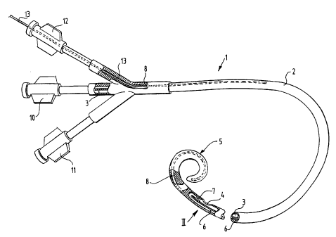
Figure 1 illustrates a partly broken away view
of a suction catheter according to an embodiment of the
invention.
Figure 2 shows an enlarged detail indicated by
arrow II in figure 1.
Figure 3 illustrates a cross-section along the
line III-III in figure 2.
Figure 4 illustrates schematically the use of
the suction catheter.
The catheter 1 illustrated in figure 1
comprises a basic body 2, in which, at a distance from the
distal end, a suction inlet 4 has been formed. This
suction inlet 4 is connected with a discharge lumen, which
extends from this opening 4 in the proximal direction to
the proximal end of the catheter. There the discharge
lumen 3 opens into a discharge connection 10. From the
suction inlet 4, a preformed, curved and pliable tip 5
extends in the distal direction to the distal end. The
curve is of the pigtail-type.
As can be seen in the figure, the tip 5 is
curved in the direction in which the suction inlet 4 is
pointing.

CA 02206015 2000-12-11
2B
As a result the suction inlet 4 is at all times kept at a
certain distance from the wall of a blood vessel into
which the catheter has been introduced.
The catheter shown in figure 1 is a preferred
embodiment wherein the suction action at the suction

CA 02206015 1997-OS-23
3
inlet 4 is effected by means of ejector action. A
pressure lumen 6 has been arranged inside the basic body
2 which ends close to the relatively distal end of the
suction inlet 4, that is to say on the left-hand side in
figure 1, in a jet nozzle 7 which is directed in the
opposite, proximal direction along the suction inlet in
the discharge lumen 3.
As can be seen in greater detail in figure 2, a
fluid jet can be directed along the opening 4 by means of
the jet nozzle 7, as a result of which suction will be
generated at the suction inlet 4 due to the ejector
action. The material sucked in will be passed along by
the liquid released from the jet nozzle 7 through the
discharge lumen 3 to the discharge connection 10.
At the proximal end the pressure lumen 6 is
connected to a pressure connection 11.
For the purpose of introducing the catheter 1,
the curved tip 5 can be straightened by using a guide
wire 13, which is advanced through a guide-wire-lumen 8
arranged for that purpose inside the basic body 2. At the
proximal end this guide- wire-lumen 8 is connected with a _
guide-wire-connection 12.
It should be noted that the connections 10, 11
and 12 in the figures 1 and 4 have only been illustrated
schematically. A catheter used for the purpose described
will have been provided at the proximal end with
haemostatic devices in order to prevent undesired leaking
out of blood via the lumens of the catheter.
As can be seen in figure 4, the catheter 1 with
the curved preformed tip 5 can be employed in large blood
vessels and even be advanced through the heart 15 into
the pulmonary artery. Because of the preformed curve, the
suction inlet 4 is positioned in a stable manner as
required. The suction inlet 4 cannot attach itself to the
wall as it is kept, by means of the curve 5, at a certain
distance from the walls of the blood vessel.
Although the guide-wire-lumen in the example of
an embodiment shown extends right from the proximal end

CA 02206015 1997-OS-23
4
to the distal end, the catheter according to the
invention can also be given the embodiment of a 'rapid
exchange'-type. In that case the guide-wire-lumen extends
from an opening in the wall of the basic body 2
positioned at a limited distance from the distal end to
the distal end. With such an embodiment the guide-wire-
lumen can be formed in the end-section only in a suitable
manner. In that case the guide-wire-lumen does not take
up any space in the section of the basic body through
which the discharge lumen 3 and the pressure lumen 6
extend. These can in that case be given an optimum cross-
section for the purpose of ejector action.
The tip may be connected to the remaining part
of the catheter in any suitable manner, for instance by
means of glueing or welding. The specific shape of the
curve may be adapted to the required operative position.
The tip may have been manufactured in a suitable manner
of a plastic material opaque to X-rays, so that the tip
can be made properly visible on an X-ray screen.

Representative Drawing
A single figure which represents the drawing illustrating the invention.
Administrative Status

For a clearer understanding of the status of the application/patent presented on this page, the site Disclaimer , as well as the definitions for Patent , Administrative Status , Maintenance Fee  and Payment History  should be consulted.

Administrative Status

Title Date
Forecasted Issue Date 2003-01-21
(22) Filed 1997-05-23
(41) Open to Public Inspection 1997-11-29
Examination Requested 2000-07-07
(45) Issued 2003-01-21
Expired 2017-05-23

Abandonment History

There is no abandonment history.

Payment History

Fee Type Anniversary Year Due Date Amount Paid Paid Date
Registration of a document - section 124 $100.00 1997-05-23
Application Fee $300.00 1997-05-23
Maintenance Fee - Application - New Act 2 1999-05-24 $100.00 1998-11-12
Maintenance Fee - Application - New Act 3 2000-05-23 $100.00 1999-11-18
Request for Examination $400.00 2000-07-07
Maintenance Fee - Application - New Act 4 2001-05-23 $100.00 2000-11-30
Maintenance Fee - Application - New Act 5 2002-05-23 $150.00 2001-12-12
Final Fee $300.00 2002-11-06
Maintenance Fee - Patent - New Act 6 2003-05-23 $150.00 2003-01-15
Maintenance Fee - Patent - New Act 7 2004-05-24 $150.00 2003-11-17
Maintenance Fee - Patent - New Act 8 2005-05-23 $200.00 2004-11-22
Maintenance Fee - Patent - New Act 9 2006-05-23 $200.00 2006-01-31
Maintenance Fee - Patent - New Act 10 2007-05-23 $250.00 2007-04-10
Maintenance Fee - Patent - New Act 11 2008-05-23 $250.00 2008-04-10
Maintenance Fee - Patent - New Act 12 2009-05-25 $250.00 2009-04-20
Maintenance Fee - Patent - New Act 13 2010-05-24 $250.00 2010-04-14
Maintenance Fee - Patent - New Act 14 2011-05-23 $250.00 2011-04-13
Maintenance Fee - Patent - New Act 15 2012-05-23 $450.00 2012-04-11
Maintenance Fee - Patent - New Act 16 2013-05-23 $450.00 2013-04-10
Maintenance Fee - Patent - New Act 17 2014-05-23 $450.00 2014-04-09
Maintenance Fee - Patent - New Act 18 2015-05-25 $450.00 2015-04-29
Maintenance Fee - Patent - New Act 19 2016-05-24 $450.00 2016-05-16
Owners on Record

Note: Records showing the ownership history in alphabetical order.

Current Owners on Record
CORDIS EUROPA N.V.
Past Owners on Record
REEKERS, JAN ALBERTUS
Past Owners that do not appear in the "Owners on Record" listing will appear in other documentation within the application.
Documents

To view selected files, please enter reCAPTCHA code :


To view images, click a link in the Document Description column. To download the documents, select one or more checkboxes in the first column and then click the "Download Selected in PDF format (Zip Archive)" or the "Download Selected as Single PDF" button.

List of published and non-published patent-specific documents on the CPD .

If you have any difficulty accessing content, you can call the Client Service Centre at 1-866-997-1936 or send them an e-mail at CIPO Client Service Centre.


Document
Description 
Date
(yyyy-mm-dd) 
Number of pages   Size of Image (KB) 
Cover Page 1998-01-28 1 40
Representative Drawing 2002-12-17 1 11
Cover Page 2002-12-17 1 37
Abstract 1997-05-23 1 15
Description 1997-05-23 4 163
Claims 1997-05-23 1 32
Drawings 1997-05-23 3 70
Claims 2000-12-11 2 84
Description 2000-12-11 6 224
Claims 2002-06-25 2 85
Representative Drawing 1998-01-28 1 7
Assignment 1997-05-23 2 102
Correspondence 1997-07-31 1 33
Assignment 1997-08-21 4 146
Prosecution-Amendment 2002-06-25 3 83
Prosecution-Amendment 2000-12-11 8 276
Correspondence 2002-11-06 1 52
Prosecution-Amendment 2002-02-27 1 32
Prosecution-Amendment 2000-07-07 1 53