Note: Descriptions are shown in the official language in which they were submitted.
CA 02206437 2004-O1-23
1
METHOD OF DETERMINING REMAINING LIFE OF A POWER
TRANSMISSION BELT
BACKGROUND OF THE INVENTION
FIELD OF THE INVENTION
This invention relates to power transmission belts and more particularly, to a
method of effectively determining the remaining life of a power transmission
belt.
BACKGROUND ART
It is common for automobile makers to collect and investigate data pertaining
to the life of power transmission belts on engines subjected to road running
tests to
estimate the remaining life thereof. It is desirable to be able to make a
reasonable
estimate of remaining life after a relatively short running distance.
This type of power transmission belt is commonly made with a rubber body
having short fibers embedded therein. The fibers project laterally between
spaced,
pulley-engaging side surfaces to increase lateral pressure resistance and
reduce rubber
wear. The fibers have exposed portions at the side surfaces. Exemplary of such
a belt
is that shown in Japanese Provisional Patent Publication of Mishima, No. 7-
4470,
published January 10, 1995 and assigned to the assignee herein. (See the
related U.S.
patent No. 5,413,538 issued May 1995).
In Figs. 4 and 5 herein, a V-ribbed belt, as in Japanese Provisional
Patent Publication No. 7-4470, is shown at 10. The belt 10 has a body 12 with
load carrying cords 14 embedded therein and extending lengthwise of the belt
10.
The belt body 12 has an outer surface 16 to which two layers 18 of canvas
are adhered. A plurality of and in this case three, V-shaped ribs 20 are
provided on
CA 02206437 1997-OS-29
AP-1634
2
the inside of the belt body 12. The ribs 20 are spaced laterally from each
other
and extend in a lengthwise direction. The ribs 20 are made from rubber within
which short, reinforcing aramid fibers 22 are embedded. The ribs 20 also have
embedded therein short, non-aramid, reinforcing fibers 24 which have a wear
resistance that is less than that of the aramid fibers 22. The fibers 22, 24
have
lengths oriented generally in a lateral direction. The fibers 22, 24 project
from
0.1 to 3.0 mm from oppositely facing rib surfaces 26, 28, which surfaces 26,
28
engage complementary surfaces on a cooperating pulley (not shown).
With the belt 10 trained around a cooperating pulley, the projecting
portions of the aramid fibers 22 are bent by the pulley against the rib
surfaces 26,
28. This reduces wear on the rubber in the ribs 20 by the pulley during use.
Further, the projecting portions of the fibers 22 reduce the coefficient of
friction
between the rubber in the ribs 20 and the cooperating pulley, thereby reducing
noise generation resulting from the ribs 20 momentarily sticking on the
pulley.
~5 The non-aramid fibers 24 prevent the bent aramid fibers 22 from pressing
into the rubber defining the surfaces 26, 28. The aramid fibers 22 thus remain
between the rubber in the ribs 20 and cooperating pulleys. If the bent fibers
22
were allowed to embed in the rubber defining the surfaces 26, 28, the sides of
these fibers 22 would be exposed, thereby making slippage between the belt 10
2 o and cooperating pulley more likely.
By reason of having the aramid fibers bent without being embedded in the
surfaces 26, 28, the belt 10 is allowed to seat more deeply into cooperating
pulley
grooves, which thereby reduces belt tension, as at initial system set up.
After the
belt 10 is run for a period of time, the aramid fibers 22 bent by the pulleys
25 against the exposed non-aramid fibers 24 are pinched and eventually
severed.
CA 02206437 2004-O1-23
3
The aramid fibers 22 wear away, as shown in Fig. 5, at roughly the time that
the tension
of the belt, which reduces as the belt operates, has stabilized. Once the
fibers 22 wear
away, the coefficient of friction between the belt 10 and cooperating pulleys
increases,
thereby improving power transmission performance.
To estimate or determine.the remaining life of the above power transmission
belt 10 using conventional techniques, the surfaces 26, 28 are visually
observed. The
abnormal conditions of the belt are divided into five different evaluation
categories,
identified as A - E, as in Table 1, below.
TABLE 1
Evaluation Result of visual observationCoefficient of
Category remaining life
A No abnormality observed. 1 or more
B Cracks about one half the one half
height
of rubber transmission
section
observed.
C Cracks over the height one quarter
of rubber
transmission section observed.
D Rubber transmission sectionzero
broken.
E Rubber transmission sectionzero
severed.
A coefficient of the remaining life is determined by dividing the travelling
distance until the belt life expires after a particular observation point by
the running
CA 02206437 2004-O1-23
4
distance up to the observation point, hereinafter referred to as the "actual
running
distance".
It is difficult to make meaningful estimations of remaining life when the
actual
running distance is only a short distance. For example, there are many
evaluations
which will fall into category A where no abnormality is identifiable by an
unmagnified,
visual observation. As a result, the coefficient of the remaining life would
be estimated
as 1 or more, although there is actually a considerable difference in the
remaining life.
As an alternative to mere visual observation, it is known to measure the
hardness of the rubber in the belt. However, this estimation varies greatly
depending
upon operating conditions.
SUMMARY UF' THE INVENTION
In one form of the invention, a method is provided for effectively determining
remaining life of a power transmission belt. The method includes the step of
providing
a power transmission belt having a) a body having a rubber material with a
length and
laterally spaced surfaces to engage a cooperating pulley and b) a plurality of
fibers
embedded in the rubber material and projecting in a lateral direction so that
a plurality
of the fibers have a portion that is exposed at one of the laterally spaced
surfaces. The
method further includes the step of magnifying the one laterally spaced
surface to
identify cracks in the rubber at the fiber portion. Based on at least one of
the nature
and quantity of cracks in the rubber material, the remaining life of the power
transmission belt is effectively determined.
The remaining life may b~ effectively. determined or estimated on the number
of cracks in the rubber material at the fiber portions andlor based on the
number of
CA 02206437 2004-O1-23
cracks in the rubber material spanning between the fiber portions.
Cracks which are invisible to the naked eye develop and grow around the
exposed portions of the fibers with the passage of time. As the cracks grow in
number
5 and extent, the remaining belt life decreases.
A coefficient of one or more, which decreases with the number of cracks in the
rubber material at the fiber portions and the number of cracks in the rubber
material
spanning between the fiber portions, may be assigned and multiplied by the
actual
running distance to estimate the remaining life.
Five different coefficients, each indicative of a different abnormal condition
for
the power transmission belt, may be assigned.
The abnormality to which the coefficient is assigned may be at least one of an
abnormality in the fibers or an abnormality in the rubber material in which
the fibers
are embedded.
In one form, a first coefficient is assigned that is indicative of
irregularities in
the short fibers, a second coefficient is assigned indicative of cracks in the
rubber
material around some of the fiber portions, a third coefficient is assigned
indicative of
cracks in the rubber material around all of the fiber portions or cracks in
the rubber
material around only some of the fiber portions arid spanning between the
fiber
portions, a fourth coefficient is assigned indicative of cracks in the rubber
material
around substantially all of the fiber portions with only some cracks in the
rubber
material spanning between the fiber portions and a fifth coefficient is
assigned indicative
of all cracks in the rubber material spanning between the fiber portions.
CA 02206437 1997-OS-29
AP-1634
6
The coefficients may increase from the fifth coefficient to the first
coefficient.
The coefficient may be assigned so that a first coefficient is indicative of
cracks in the rubber material around the fiber portions and a second
coefficient
is indicative of cracks in the rubber material spanning between the fiber
portions,
with the first coefficient being greater than the second coefficient.
The coefficients may be assigned values between 1 and 2.
Magnifying may be carned out as through a microscope, an electron
microscope, or a magnifying glass.
1 o The invention also contemplates a method of estimating the remaining life
of a power transmission belt, which method includes the steps of providing a
power transmission belt having a) a body made of a rubber material with a
length
and laterally spaced surfaces to engage a cooperating pulley and b) a
plurality of
fibers embedded in the rubber material and projecting in a lateral direction
so that
~5 a plurality of the fibers have a portion that is exposed at one of the
laterally
spaced surfaces. The method may include the step of magnifying one laterally
spaced surface to identify a condition that is not observable without
magnification. Based on the condition that is not observable without
magnification, the remaining life of the power transmission belt may be
2 o estimated.
The step of estimating the remaining life of the power transmission belt
may include the step of assigning coefficients indicative of at least one of
cracks
in the rubber material and irregularities in the fibers and multiplying actual
running distance for the power transmission belt by the coefficient to
estimate the
2 5 remaining life.
CA 02206437 2003-06-03
7
The coefficients may be predetermined based on actual belt operations.
The invention allows the remaining life of a power transmission belt to be
meaningfully estimated through a simple process. The estimation can be made
after a
relatively short running distance, even though abnormality is not detectable
by the
naked eye. Several different criteria can be used to make this analysis.
BRIEF DESCRIPTTON OF THE DRAWINGS
Fig. 1 shows five different schematic representations of conditions observable
under magnification and used to estimate the remaining life of a power
transmission
belt, according to the present lalvellt(Orl.
Fig. 2 is a schematic representation of a dynamic testing device for a power
transmission belt.
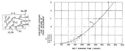
Fig. 3 is a graph showing the results of a dynamic test for the inventive
power
transmission belt.
Fig. 4 is a fragmentar-~,~, perspective view of a V-ribbed belt, (PRIOR ART),
of
the type with which the present method can be practiced.
Fig. 5 is :rn enlarged, fragmentary, cross-sectional view of a rib on the
belt,
(PRIOR ART), in Fig. 4.
Fig. 6 is a photomicrograph of a surface of a power transmission belt showing
a first condition used to estimate the remaining life of a power transmission
belt,
according to the present invention.
Fig. 7 is a photomicrograph of a surface of a power transmission belt showing
a second condition used to estimate the remaining life of a power transmission
belt,
according to the present invention.
CA 02206437 2003-06-03
8
Fig. 8 is a photomicrograph of a surface of a power transmission belt showing
a third condition used to estimate the remaining life of a power transmission
belt,
according to the present invention.
Fig. 9 is a photomicrograph of a surface of a power transmission belt showing
a fourth condition used to estimate the remaining life of a power transmission
belt,
according to the present invention.
Fig. 10 is a photomicrograph of a surface of a power transmission belt showing
a fifth condition used to estimate the remaining life of a power transmission
belt,
according to the present invention.
DETAILED DESCRIPTION C)F' TI-IE DRAWINGS
The power transmission belt 10, previously described, is but exemplary of the
different types of belts with which the inventive methad can be practiced. The
invention
can be practiced with virtually any type of power transmission belt in which
one or more
ribs fit into complementary grooves on a cooperating pulley and in which short
reinforcing fibers are embedded for lateral stability and exposed at pulley-
engaging side
surfaces on the belt rib(s).
According to the invention, the remaining life of the power transmission belt
10 is estimated using evaluatio~u different subcategaries of abnormality, as
identified by
A-1, A-2, A-3, A-4 and A-5 in Fig. 1 and in 'fable 2, below. The remaining
belt life is the
running distance from the actual running distance to the point that the state
of
evaluation category D (Table 1 ) is reached, i.e. the remaining life reduces
to zero. The
abnormalities in A-1 through .A-5 are not detectable by visual observation
using the
naked eye. Each abnormality is observable such as by use of an electron
microscope, a
CA 02206437 2003-06-03
9
microscope, or a magnifying glass. T:he different subcategories relate to the
nature and
degree of cracking .in rubber material at one of the exemplary belt surfaces
26, 28.
Cracks which are invisible to the naked eye generally first develop around the
fibers 22 24, with the number increasing over time. Progressive crack
development
through continued use causes the cracks to "span" between fibers 22, 24.
It should be initially noted, as will be demonstrated using the various
photomicrographs in Figs. 6 to 10 herein, that the aramid and non-aramid
fibers 22, 24,
respectively, vary in diameter. For purposes of explanation with respect to
I~ig. 1, the
diameter of the fibers 22, 24 will be depicted as the same.
In Fig. 1, K identifies generically cracks in the rubber material defining the
surfaces 26, 28. K, identifies cracks observed around exposed portions 30 of
the fibers
22, 24, with KZ identifying cracks spanning between the exposed portions 30 of
the fibers
22, 24.
Subcategory A-1, as depicted in Fig. 1(a), is a condition in which the
projecting
portions of the aramid fibers 22 are still intact and no rubber irregularities
are observed.
Irregularities in the projecting portions of the aramid fibers 22 are
observed. Subcategory
A-2, as depicted in Fig. 1(b), is a condition in which the projecting portions
of the
aramid fibers 22 have been severed and cracks K, are observed around some of
the fibers
22, 24. Subcategory A-3, as depicted in Fig. 1(c), is a condition in which
cracks K, are
observed around substantially all of the fibers 22, 24 or cracks are observed
around
substantially less than all of the exposed fiber portions 30 but these cracks
span between
the fiber portions 30 to form bridging cracks Kz. Subcategory A-4, as depicted
in Fig.
CA 02206437 2003-06-03
1(d), is a condition in which cracks are observed around almost all of the
exposed fiber
portions 30 and bridging portions KZ are partly formed therein. Subcategory A-
5, as
depicted in Fig. 1(e), is a condition in which the cracks Kz span between
almost all of the
5 short fibers.
When a large number of belt samples 10 are subjected to a road running test,
or a simulation test equivalent thereto and the evaluation categories are
divided into the
above-described subcategories A.-1, A-2, A-3, A-4, A-5 and the categories B,
C, D and E,
the average values of the actual running distances of the samples in each of
the
10 categories/subcategories are taken as a" a2, a3, a4 and as and b, c, d and
e. The evaluation
subcategary D shows a condition in which the rubber material is broken and a
condition
in which the belt life has already expired. Thus, the value obtained by
subtracting a"
a2, a3, a4, as and b, c from the running distance d leading to the evaluation
category D
will give the remaining life ~.
Thus, if the remaining lives of the power transmission belts divided into the
evaluation subcategaries A-1, A-2, A-3, A-4 and A-5 are taken as ~" ~2, ~3, ~4
and ~5, they
are determined as follows:
y=d-al
~l2 = d-a;
r~3 = d - a;;
'~a = d - a4
X15 = d-as
Next, the coefficients for the remaining life of the belt 10 are estimated
from the ratios of the above remaining lives to the actual running distances.
If
CA 02206437 1997-OS-29
AP-1634
11
the ratios are taken as x1, x2, K3, x4, and x5, respectively, they are
determined as
follows.
K1 = r1 1/a, _ (d/al) - 1
~ = r1 2/a2 _ (~az) - 1
x3 = rl3/a3 = (d/a3) - 1
K4 = r1 4/a4 = (d/a4) - 1
K5 = r1 5/a5 = (d/as) - 1
It is known that the power transmission belt of evaluation category A has
a remaining life of at least equal to the present running distance or more and
the
to coefficient for the remaining life becomes 1 or more.
If the above-described coefficients for remaining life are obtained in
advance for each type of power transmission belt, the remaining lives r~ 1, '~
z, r1 3,
r14, and r1 s could be estimated by multiplying the actual running distances
a1, a2,
a3, a4 and as by the aforementioned coefficients of remaining life Kl, K2, K3,
K4, and
Ks.
It is also possible to further divide a) the evaluation subcategory A-1 using
proportions of abnormalities observed, b) the evaluation subcategory A-2 by
proportions of cracks K, around the short fibers, and c) the evaluation of
subcategories A-3 to A-5 by a combination of proportions of cracks K, around
2 o the short fibers and proportions of spanning portions KZ between the short
fibers.
EXAMPLE
The power transmission belt 10 was used to obtain the coefficients of
remaining life Kl, Ky K3, K4, and x~ through experimentation. The rubber
material
CA 02206437 1997-OS-29
AP-1634
12
in the belt body was made of 5 parts by weight of aramid short fiber and 13
parts
by weight of nylon short fibers per 100 parts by weight of chloroprene rubber.
The length of the aramid short fibers and the non-aramid short fibers was 2 to
10
mm. The belt had a V-shaped rib with a circumferential length of 1100 mm.
In Fig. 2, a dynamic testing device is shown at 40 for the power
transmission belts. The testing device 40 has a driving pulley 42 with a
diameter
of 120 mm that is rotated at a speed of 4900 rpm, a driven pulley 44 having a
diameter of 120 mm and a load of 12 P.S., a stationary pulley 46 having a
diameter of 45 mm and loaded with an initial load of 57 kgf, and an idler
pulley
48 having a diameter of 85 mm. The system was run at an ambient temperature
of 85 ° C.
The belt 10 was trained around the pulleys 42, 44, 46, 48 and operated.
The operation was interrupted at predetermined intervals to determine the
amount
of crack development to produce data for evaluation purposes. The results are
shown in Fig. 3.
In the test device 40, with the drive pulley 42 rotated at a constant speed,
the running distance is proportional to the operating time. For purposes
herein,
the running distance will be expressed in terms of a "running time".
Referring to Fig. 3, the relationship between the running time and the
2 o degree of crack development is identified by black spots, with the
approximate
average of the data represented by a curve ~,. The average values of the
present
running time by the evaluation classes were a, = 128 hours, a2 = 142 hours, a3
=
170 hours, a4 = 180 hours, a5 = 200 hours, b = 262 hours, c = 318 hours, d =
399
hours, and a = 418 hours.
CA 02206437 1997-OS-29
AP-1634
13
Data accumulated through a road running test was added to these
experimental results to set the coefficients of remaining life to KI = 2.00,
x2 =
1.75, x3 = 1.50, x4 = 1.25, and KS = 1.00. The relationships therebetween are
summarized in Table 2, below.
TABLE 2
Evaluation Results of Visual ObservationCoef~'lcient
of
Subcategory Under Magnification Remaining Life
A-1 Abnormalities of short fibers2.00
observed.
A-2 Irregularities of short fibers1.75
eliminated, and cracks observed
around short fibers.
1o A-3 Cracks observed around alinost1.50
all
of short fibers, or a few
cracks
observed but the cracks span
between short fibers.
A-4 Cracks observed around almost1.25
all
of short fibers, and some
of cracks
between short fibers are spanning.
A-5 Almost all of cracks are spanning1.00
between short fibers.
After determining the coefficients of remaining life through
experimentation for the power transmission belt, the remaining life can be
estimated from the state of crack development which is not visually observable
through the naked eye.
CA 02206437 2003-06-03
14
Samples of photomicrographs of evaluation subcategories taken from the side
surface 26 of the power transmission belt 10 are shown in Figs. 6 - 10. Fig. 6
is a
photomicrograph corresponding to the condition in subcategory A-1. Fig. 7 is a
photomicrograph corresponding to the condition in subcategory A-2. Fig. 8 is a
photomicrograph corresponding to the condition in subcategory A-3. Fig. 9 is a
photomicrograph corresponding to the condition in subcategory A-4. Fig. 10 is
a
photomicrograph corresponding to the condition in subcategory A-5.
In the photomicrographs, of the sham fibers which are circular in cross
section,
the thicker ones are non-aramid short fibers, with the thinner ones being 10
the aramid
short fibers. Black and thin portions are cracks, with the cracks tending to
form more
readily around the non-aramid short fibers.
With the invention, the remaining life of the belt can be predicted with
meaningful accuracy even thou h the belt surfaces appear to be perfect to the
naked eye.
The data analysis is accumulated under magnification. This allows prediction
of life
expectancy after a relatively short running time as in a road running test. By
predetermining the correspondence between the categorized abnormalities and
the
remaining belt life in advance through experimentation, coefficients can be
predetermined and used to estimate remaining belt life for belts having a
similar
construction to those pre-run. Meaningful numerical life expectancies can thus
be
established using the present invention.
The foregoing disclosc.ire of specific embodiments is intended to be
illustrative
of the broad concepts comprehended. by the invention.