Note: Descriptions are shown in the official language in which they were submitted.
CA 02206467 1997-OS-29
METHOD f'OR ASYMMETRICALLY ATTENUATING SIGNALS IN A
TRANSMISSION SYSTEM
Technical Field
This invention relates to a technique for attenuating downstream and upstream
signals in a hybrid fiber-coax system by different weights to reduce ingress
noise.
l3ac ~ctr~und Art
In present dsy hybrid fiber-coaac transmission systems, downstream information
destined for individual subscribers originates at a head end. From the head
end, the
downstream information is typically optically formatted for transmission over
a fiber
optic link to a fiber node at which the information is then converted to an
electrical
signal. A coaxial cable network (plant) transmits the electrical signal to the
individual
subscribers and carries upstream signals from the subscribers to the fiber
node for
ultimate delivery to the head end..
Within the coaxial cable plant, the downstream electrical signal is typically
amplified by one or more trunk amplifiers and one or more line extenders
before
distribution via taps to subscriber premises. (Upstream signals are similarly
amplified by
upstream trunk amplifiers and line extenders.) The power of the downstream
signal
received at each prrmises is reduced by the loss in the cable as well as the
inherent power
splitting at each tap. For example, a tap saving two homes will split the
power 2:1
whereas a tap serving four homes would split the power 4:1. To achieve an
adequate
power level at each premises, the tap weight, (i.e., the level of attenuation
provided by
each tap) is selected to obtain approximately the same loss at all homes.
Hence, the tap
weights must decrease in acccordance with the distance that the downstream
signal
traverses from the downstream amplifiers and line extenders because of
increasing cable
losses plus the decreased power level caused by the energy siphoned off at
previous taps.
Equal losses, and therefore, equal received power levels for each home assures
a
sufficiently high signal to overcome any noise that may be present in the
home.
CA 02206467 2000-OS-25
2
In present day hybrid fiber coax systems, the taps have symmetric losses. In
other
words, downstream signals that pass to the subscriber premises are attenuated
by each tap to
same degree (except for small variations due to their different frequency) as
upstream signals
received at each tap from the subscriber premises. Just as it is desirable to
achieve a uniform
signal level for downstream signals at the subscriber premises, it is also
desirable to achieve a
uniform level for upstream signals received at each upstream amplifier in the
cable plant.
Since the tap weights are fixed, the level of signals emanating from the
customer premises
equipment (CPE) at the subscribers' premises must be varied to assure that the
received
upstream signals all have approximately the same level at a common upstream
amplifier.
Hence, the subscriber premises closest to the upstream amplifier must have the
highest CPE
output level to compensate for the highest tap value. Conversely, the
subscriber premises
furthest from the upstream amplifier generally will have the lowest signal
level. In practice,
the tap weights vary in 3 dB increments. Thus, the actual signal levels
received at various
subscriber premises may vary somewhat from a uniform desired level.
The use of present day symmetric taps incurs a difficulty associated with
ingress noise
from each subscriber premises and its associated cable drop through which the
premises is
connected to the cable plant. Noise entering the tap most distant from the
upstream amplifier
has a much greater effect on performance because of the low loss associated
with this distant
tap. At the same time, the level of the subscriber-generated CPE output signal
entering the
most distant tap is lower than the more closer taps, making its signal to
noise ratio lower.
Thus, there is a need for a technique for reducing ingress noise in a hybrid
fiber coax
system.
Brief Summary of the Invention
In accordance with one aspect of the present invention there is provided a
method for
transmitting a downstream signal through at least one cable in a distribution
network to
individual subscribers and for transmitting upstream signals from subscribers
through the
cable, comprising the steps of: supplying the downstream signal to individual
subscribers via
a string of taps cascaded along the cable, each tap having a successively
decreasing
downstream attenuation weight as compared to an upstream neighboring tap for
attenuating
CA 02206467 2000-OS-25
3
the downstream signal so that the downstream signal received at a distant most
tap has
substantially the same signal strength as the downstream signal received at a
closest tap; and
attenuating, at each tap, the upstream signal from an associated subscriber by
an amount such
that the taps provide an aggregate upstream attenuation different than an
aggregate
downstream attenuation, the upstream attenuation of each tap established such
that the level
of the upstream signal received from said each associated subscriber in the
distribution
network is substantially equal for all subscribers wherein the upstream
attenuation provided
by each tap is set by subtracting, from a given subscriber upstream signal
level, a desired
level for the upstream signal within the distribution network, a cumulative
cable loss
associated with said tap and cumulative tap losses associated with said taps.
Brief Description of the Drawings
FIGURE 1 is a block diagram of a hybrid fiber-coax transmission system in
accordance with the prior art;
FIGURE 2 depicts a portion of the transmission system of FIG. 1, showing the
downstream attenuation weights of each of a set of taps within the system;
FIGURE 3 depicts the same portion of the transmission system as in FIG. 2,
indicating the upstream attenuation weights for the taps;
FIGURE 4 is a block diagram of an asymmetric through tap in accordance with
the
invention;
FIGURE 5 is a block schematic diagram of an asymmetric terminating tap in
accordance with the invention;
FIGURE 6 depicts a modification of the transmission system of FIG. 1 in
accordance
with a first embodiment of the invention, wherein asymmetric taps have been
substituted for
the symmetric taps of FIG. 1; and
CA 02206467 1997-OS-29
Detailed DescriptiQp
FIGURE 1 depicts a hybrid-fiber-coax transmission system 10 in accordance with
the prior art. T'he system 10 includes a head end 12 for generating
information, e.g.,
video, audio, multimedia, data and/or text ("dovvnstream information") for
transmission
to individual subscribers 14-14. The head end 12 also receives information,
("upstream
information"); e.g., video, audio, multimedia, data and/or text; generatai by
one or more
of the subscribers 14-14.
In practice, a combination of optical fibers and coaxial cables carry the
downstream information from the head end 12 to the subscribers 14-14 and carry
the
upstream information from the subscribers to the head end. As seen in FIG. 1,
an optical
fiber link 16, comprised of an upstream and down stream fibers (not shown),
carries both
the upstream and dowa~am information in an optical format between the head end
12
and a fiber node 18. fhe fiber node 18 converts the optically-formatted
downstream
information received fibm the head end 12 into electrical signals for
distribution via a
coaxial cable distribution network 20 to the individual subscribers 14-14.
Further, the
fiber node 18 converts upstream information, received from subscribers 14-14
via the
coaxial cable distribution network 20, into an optically-formatted signal for
transmission
to the head tnd 12. Note that upstream and dovvns>aream signals could pass
electrically
between the head end 12 and the network 20 via coaxial cable, rather be
optically
formatted for passage via the fiber optic link 16.
The cable distribution network 20 has a tree and branch architecture and,
typically
includes at least one, and typically four coaxial trunk cables 22-22 (only one
shown).
Each of the trunk cables 22-22 typically has at a plurality of branching trunk
amplifiers
24-24 cascaded along its length for amplifying the upstream and downstream
information.
(In practice, each branching trunk amplifiers is comprised of individual
amplifying
CA 02206467 1997-08-29
elements and diplexers (not shown) that separately amplify the upstream and
downstream information).
Each branching trunk amplifier 24 feeds one or more distribution cables
26-26. Each distribution cable 26 typically has one or more line extenders 28-
28
5 cascaded along its length for amplifying the upstream and downstream
information
carried by each distribution cable. Each distribution cable 26 contains a
plurality of
taps 30~-30g disposed in cascaded fashion between pairs of line extenders 28-
28
(only the taps 30,-308 are shown in FIG. 1.) It should be understood that a
greater
or smaller number of taps may be present. The taps couple the distribution
cable 26
to a plurality of subscribers 14-14 via individual coaxial drop cables 32-32
that
each connect a subscriber to a tap via a separate one of network interface
units
(NILI) 34-34.
FIG. 2 depicts a portion of a distribution cable 26 of the network 10,
showing a string of cascaded taps 30~-308 that successively attenuate the
signal
generated by a first of a pair of downstream line extenders 28-28 (only one
shown).
The weights (i.e., attenuation) of the taps 30,-308 generally successively
decrease in
accordance with the distance of the tap from the line extender 28 in FIG. 2.
Thus,
the tap 30,, which is closest to the line extender 28, has a weight
significantly
greater than the weight of the tap 308 which is furthest from the line
extender.
The tap weights are chosen to successively decrease as a function of the
distance of the tap from the line extender 28 to assure a substantially
uniform output
level at each tap. There are several factors that influence the selection of
tap
weights. The branch distribution cable 26 along which the taps 30~-30$ of FIG.
2
are cascaded has a certain loss per unit length. Thus, to assure approximately
the
same received level at the upstream line extender from each of the taps 30~-
30g, it
follows that the tap 30g must have a smaller weight than the tap 30,.
Moreover, each of the taps 30,-308 has a certain loss associated with the
passage of signals therethrough. Since the taps 30,-308 are cascaded, the
aggregate
tap loss, as measured at the tap 308, will be sum of the losses of the signals
through
the preceding taps. For this reason as well, the weight of the tap 308 must be
less
than the weight of the tap 30,.
CA 02206467 1997-OS-29
6
In the illustrated embodiment of FIG. 3, the loss of the distribution cable 26
at 750
MHz is assumed to be -1.5 dB between successive pairs of the taps 30,.30 which
are
presumed to be equally spaced. Further, the taps 30i-30s are presumed to have
through-
losses as indicated by values depicted in FIG. 2. Under these conditions, a
tap output
level of approximately 18~.1 dB for each subscriber 14-14 can be achieved for
as line
extender 28 output value of +45 dB by selecting the tap weights as indicated
in Table I.
TABLEI
Tap No. Tap Weight
301 26 dB
3~ 23 dB
303 20 dB
304 17 dB
30s 14 dB
306 11 dB
30~ 8 dB
30a 4 dB
The prior art taps 30~-30= are symmetric in terms of the attenuation each
provides
to upstream and downstream signals. In other words, each tap attenuates
upstream and
downstream signals by the same weight. Since the taps are symmetric in tenus
of their
attenuation, achieving a substantially constant level for upstream signals
received at the
line extender 28 requires that the level of upstream signals provided by the
subscribers be
successively smaller for distant taps. This may understood by reference to
FIG. 3 which
depicts the upstream weights of the cascaded taps 30,-30s. Assuming that the
taps 30,-
30= of FIG. 3 have upstream weights as given in Table I, then,, in order to
achieve a
substantially constant upstream signal level at the line extender 28 for the
cable and tap
CA 02206467 1997-OS-29
losses previously with respect to Table I , the CPE level of signals input to
each of the
taps 30,-30~ must be chosen as indicated in Table II
Table ll
Tap No. CPE Input Level
30, 45 dB
3~ 42.8 dH
3~ . 40.b dB
304 38.4 dB
30s 36.2 dB
306 ' 34.0 dB
3~ 31.8 dB
28.6 dH
As may be appreciated from Table B, the CPE level input to the distant_most
tap 30a is
lower, ba~use of its relatively low weight, as compared to the CPE level
required at the
tap 30, that is closest to the line extender 28.
The present-day approach of employing symmetric taps 30,-30= incurs a di~culty
with respxt to ingress noise at the premises of each subscriber 14 (FIG. 1 )
as well as the
associated drop cable 32 (FIG. 1). Noise entering a distant tap, such as tap
30= of FIGS 2
and 3, will have a much greater influence on overall system performance
ba~uuse the
weight of that distant tap is relatively small. Conversely, the level of the
CPE signal
input to such a distant tap is low. Thus, ingress noise will have a greater
impact for this
reason as well.
In acxordance with the invention, the problem of ingress noise can be reduced
by
making each tap asymmetric such that the weight of each tap is different for
upstream and
downstream signals. As will be discussed in greater detail below, making each
tap
CA 02206467 1997-OS-29
g
asymmetric enables the CPE values input to the.taps to beheld at a relatively
high
constant value, thereby minimizing the effects of ingress noix.
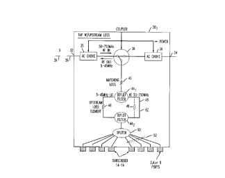
FIGURE 4 illustrates an asymmetric through tap 30,' in accordance with the
invention for subsdtuuon in place of the tap 30~ of FIG. 1. (Outer asymmetric
though
taps, each of a construction similar to the tap 30~', would be substituted for
the taps 30,-
30= of FIGS.1-3). The asymmetric tap 30t' of FIG. 4 is referred to as a
through tap
because it functions to attenuate signals passing between a pair of tap ports
32 and 34,
respectively, in contrast to a terminating tap, as further described with
respect to FIG, 5,
that terminates signals.
Referring to FIG. 4, high frequency signals originating. at the head end 12 of
FIG.
1 enter the tap 301' at the port 32 and exit via the port 34, whereas low
frequency signals
from a downstream tap enter via port 34 and exit via port 32. A pair of AC
chokes 35
and 36 are serially coupled between the tap ports 32 and 34, respectively for
filtering low
frequency power signals that share the distribution cable 26. A coupler 38 is
interposed
txtween the chokes 35 and 36 and serves to draw off a small portion the high
frequency
downstream signals entering the tap via port 32 to provide such signals to one
of more
subscribers premises 14-14. Further, the coupler 38 also serves to inject iow
frequency
signals onto the cable 26 for passage to the head end 12 of FIG. 1. The
coupler 38 is
generally directional so that upstream signals that enter the coupler pass to
the
distribution cable 26 but are substantially attenuated in the direction away
from the head
end.
A matching loss element 40 couples the coupler 38 to a filter assembly 42
comprised of an ups~r~am and downstream diplex filters 44~ and 442. The diplex
filters
441 and 442 serve to separate high frequency (50-750 MHz) downstream signals
along a
high frequency path (H) and low frequency (5-45 MHz) upstream signals along a
low
flu«Y P~ (1.). The low frequency path of the diplex filter 44, is coupled via
an
upsdreun loss element 46 to the low frequency path of the diplex filter 442.
In contrast,
the high frequency paths of the diplex filter 441 and 44I are linked by a
substantially
lossless conductor 48.
CA 02206467 1997-OS-29
9
High frequency downstream signals drawn by the coupler 38 from the
distribution
cable 26 pass via the matching loss element 40 to the upstream diplex filter
44,. The high
frequency dov~mstream signals are separated by the diplex filter 44, and pass
along its
high frequency path to the downstream diplex filter 44i via the conductor 48.
The high
frequency downstream received at the downstream diplex filter 44z are split
equally by a
sputter 50 for distribution to one or snore subscriber at subscriber tap ports
52-52. As
may be appreciated, the high frequency downstream signals drawn from the
distribution
cable 26 and output at the tap ports 52-52 are attenuated in accordance with
the weight
(impedance) of the matching loss value 40 (as well as by any parasitic losses
in the
coupler 38 and the diplex filters 44, and 44z).
Low frequency upstream signals received at the tap ports 52-52 are separated
by
the downstream diplex filter 44~ and pass along the filter's low freq~xncy
path via the
upstream loss element to the diplex filter 44, and from that filter to the
coupler 38 via the
loss element 46. As may be appreciated, the upstream low fi~quency signals are
thus
attenuated by both the upstream and matching loss elements 46 and 40,
respectively, (as
well as by any parasitic losses in the coupler 38 and the diplex filters 44,
and 44i). The
upstream attenuation achievod by the tap 30, will thus be at least as great,
if not greater
than the downstream loss aad can be independently adjusted by varying the
value of the
upstream loss element 46. Should it be desirable for the asymmetric tap 301'
of FIG 4 to
provide greater downstream attenuation than upstream attenuation, then a
downstream
loss element 49 (shown in phantom) could be substituted for the conductor 48.
In some instances, it is desirable for the asymmetric tap to terminate the
distribution cable 26, rather than pass signals therealong. FIG. 5 shows a
block schematic
diagram of an asymmetric terminating tap 300' in accordance with the
invention. The
asymmetric terminating tap 3001' of FIG. 5 is similar to the through tap 301'
and like
numbers have been used to identify like elements. The major difference between
the
terminating and through taps 3001' and 301' of FIGS. 4 and 5, respectively, is
that the
terminating tap has a single port 32 and a single AC choke 35 coupled directly
via the
matching loss element 40 to the diplex filter assembly 42. In this way, the
matching loss
CA 02206467 1997-OS-29
element 40 in the asymmetric through tap 300,'terminates the distribution
cable 26 of
FIG. 5.
With regard to the construction of the asymmetric through and terminating taps
30,' and 300,' of FIGS. 4 and 5, otlur variants are possible. In the
illustrated
5 embodiments of FIGS. 4 and 5, the asymmetric through and terminating taps
30,' and
300,', respectively, are configured of passive elements to reducx cost and
space
requirements. The asymmetric through and terminating taps 30,' and 300,' could
easily
be implemented via active circuits to achieve lower tosses or increased gain,
as well as
isolation between ports. Whether the asymmetric through and terminating taps
30,' and
10 300,' are configured of active or passive elements, the taps, in
combination, have unequal
upstream and downstream weights. Dirxtional couplets could also be used to
allow for
the creation of asymmetric tap losses in the upst~tn and downstream
directions,
The ability of the asymmetric through and terminating taps 301' and 300,' to
provide different upstream and downstream weights can be advantageously
employed to
reduce ingress noise. This may be appreciated by refereixe to FIG. 6 that
depicts a string
of cascaded asymmetric through taps 30,'-30i' substituted for the string of
symmetric taps
30,-30= of FIGS. 2 and 3. The ability of the asymmetric taps 301'-30=' of FIG.
6 to
pmvide different upstream and downstream weights allows the string of taps to
Have their
upstream weights set to permit a constant subscriber CPE level (say +45 dB)
input to each
tap, and yet achieve a substantially constant upstream signal level at the
input to the line
extender 28. The advantage of setting the CPE levels of the up~am information
supplied to the taps at a constant level allows the CPE level to be maximized
for all
subscribers, greatly redwing the effect of ingress noise, especially for
distant subscribers.
As indicated previously, with prior art symmetrical taps, the CPE levels from
subscribers
must be varied so that the most distant tap transmits the lowest CPE level.
For the embodiment illustrated in FIG. 6, the dovvnstream and upstream weights
for each of i taps (where i is an integer) will be given by the relationships:
Downatt-esm tap weiøt ~ Line extends 2E level - tksired CPE receive signal -
Cum Cable loss (until the
~'" tap) - Cum Tap through loss (through the t"-l tap)
CA 02206467 1997-OS-29
Upstraas Tap wel~6t ~ CPE Transmit level ~ Desired Received Level ~ Cum Cable
loss (until the f"
tap) ~ Cum Tap through loss (throu~t the r'. t tap)
If the cable loss between taps is -.3 dB and the individual tap loss is -.5
dH, then to
achieve a CPE level at the line extender 28 of approximately 19 dB for a CPE
transmit
level of +45 dB, the upstream weights for the taps 30t'-30= will be as
indicated in Table
III.
TABLE III
Tap Downstream Tap CPE Level at Line Upstream Tap Loss
mss Extender 28
30t' 26 dB 18.7 dB 26 dB
30I' 23 dB 18.9 dB 25 dB
303' 20 dB - 19.1 dB 24 dB
304 17 dB 19.3 dB 23 dB
30s' 14 dB 19.5 dB 22 dB
306 11 dB 19.7 dB 21 dB
3~~ 8 ~ 19.9 dB 20 dB
30a 4 dB 19.1 dB 20 dB
As compared to the taps 30t-30= of FIGS. 1-3, the taps 30t'-30= of FIG. 6 have
significantly greater weights. Indeed, the ups weight of each of the taps
301'-30=' of FIG. 6 is at least as great (and in most instances, gt~ter) t~
its downstream
weight. Providing each of the taps 30t'-30i with a large upstream weight aids
in reducing
ingress noise, The large upstream weight of each tap allows it to more
effectively block
ingress noise than if the tap had a low upstre~ weight as with the prior art
taps 30t-30=
of FIGS. 1-3.
The digital signals in an hybrid fiber-coaac environment are adversely a~'by
ingress noisy and signal reflections attributable to a lower VSWR. Use of the
asymmetric
taps in accordance with the invention reduces ingress noise from subscribers
while
CA 02206467 1997-OS-29
12
simultaneously reducing reflections by increasing the VSWR in the 5-45 IvtHz
bandwidth
on which the upstream signals typically transmitted.
The foregoing describes a transmission system that utilizes asymmetric taps
(30,'-
30i ) for attenuating upstream information by an amount different than
downstream
information to allow the upstream information to be transmitted at a constant
level,
reducing the influence of upstream noise, particularly at distant taps.
It is to be understood that the above-described embodiments are merely
illustrative
of the principles of the invention. Various modifications and changes may be
made
thereto by those skilled in the art which will embody the principl« of the
invention and
fall within the spirit and scope thereof.