Note: Descriptions are shown in the official language in which they were submitted.
CA 02206814 1997-06-03
COVERPLATE STORAGE DEVICE
Field of the Invention
This invention relates in general to a storage device and more
s particularly to a coverplate storage device.
Background of the Invention
Hooks for hanging key chains, elastic bands, dish towels and
other small items are commonly used in homes and businesses. These hooks
10 are generally attached by screwing, nailing or gluing onto a surface, such as,
a cupboard or wall. The storage device of this invention is attached without
damaging any surface and is located at a coverplate, such as a switchplate
cover for a light switch or a plug receptacle plate cover.
Other hooks have been devised for specific uses or for ease of
installation. For example, U.S. Patent 4,097,015 (Frishman) relates to a
rotatable ceiling hook, which is particularly useful for hanging plants. U.S.
Patent 4,856,953 (Lin) relates to a replaceable hook system in which the hook
is attached to a surface by a hook-driven screw. U.S. Patents 4,964,602 and
5,207,404 (Reinhard) relate to a hook or eye device having a threaded end
and in which the hook or eye end includes a configuration, such as, a phillips
configuration, to enable it to be screwed into a surface with a corresponding
type of driver. All of these hooks are attached to a wall or ceiling by screwingmeans.
The prior art hooks require a hole to be made in, or adhesive to
be applied to, a wall, ceiling, or cupboard, and if removed will leave behind
this hole or other damage to the surface. Thus a storage device which is
easily and not permanently attached and on removal does not leave a hole in,
or damage to, the wall, ceiling or cupboard is desirable.
CA 022068l4 l997-06-03
Summarv of the Invention
This invention provides an improved storage device which is
easily installed and removed and conveniently located. In the first
embodiment, the storage device is installed by removing a screw which
s secures a coverplate and replacing that screw with the storage device by
screwing the storage device into the screw receptacle to secure the
coverplate.
In accordance with one aspect of the present invention there is
10 provided a coverplate storage device comprising a first portion and a second
receiving portion, wherein said first portion is insertable into a standard screw
receptacle behind a coverplate screw slot such that said second portion
remains outside of the screw receptacle and flush with the coverplate.
In accordance with a further aspect of the present invention, the
first portion of the storage device is threaded such that insertion into the
standard screw receptacle is accomplished by screwing in the storage device.
In accordance with an aspect of the present invention, there is
20 provided a storage device comprising a screw with a washer dividing the
screw into a first and second portion, wherein, the second portion of the
storage device, from the washer to the head of the screw, is coated with a
PVC or similar suitable covering.
In accordance with a further aspect of the present invention, the
coverplate storage device is combined with a wall guard. The wall guard
comprises a rectangular-shaped thin sheet of material (such as PVC) with a
slot in the upper midpoint of the wall guard, such that, when the storage
device is installed, the first portion of the storage device passes through the
30 slot of the wall guard such that the upper end of the wall guard rests either on
top of or under the lower end of the coverplate.
CA 02206814 1997-06-03
In accordance with an aspect of the present invention, there is
provided an alternative coverplate storage device, comprising a thin sheet of
rigid material (such as PVC) having a slot in an upper end and a hook or
hooks at an outer edge, which is installed underneath a coverplate such that
the hook or hooks extend beyond the perimeter of the coverplate. The
alternative coverplate storage device is installed by removing a coverplate
and placing the second coverplate storage device under the coverplate, and
securing the coverplate with screws, one of which screws passes through the
o slot of the storage device. Alternatively, the slot in the coverplate storagedevice may fit around the switch or plug receptacle and remain in position by
this means, or a combination of the two securing means. The alternative
coverplate may also be installed above the coverplate, and for this installationthe screw of the coverplate acts as the securing means.
In accordance with an aspect of the present invention, there are
provided modifications of the alternative coverplate storage device, wherein
the hook or hooks is replaced with a pivotable rod or with a spring clip (with or
without hooks on the clip) or with a tray.
Brief Description of the Drawinqs
A detailed description of the preferred embodiments are
provided herein below with reference to the following drawings, in which:
Figure 1, in a perspective view, illusllates a coverplate storage
25 device and wall guard in accordance with the preferred embodiment of the
present invention;
Figure 2, in a perspective view, illustrates the device of Figure 1.
Figure 3, in a side view, illustrates the device of Figure 1.
Figure 4, in a top view, illusl,ates the device of Figure 1.
Figure 5, in a bottom view, illuslldles the device of Figure 1.
CA 02206814 1997-06-03
Figure 6, in a perspective view, illustrates the coverplate storage
device of Figure 1 without a covering.
Figure 7, in a perspective view, illustrates a second coverplate
storage device in accordance with a further embodiment of the present
invention.
Figure 8, in a perspective view, illustrates a third coverplate
storage device in accordance with a further embodiment of the present
invention.
Figure 9, in a perspective view, illustrates a fourth coverplate
10 storage device in accordance with a further embodiment of the present
invention.
Figure 10, in a perspective view, illustrates a fifth coverplate
storage device in accordance with a further embodiment of the present
invention.
In the drawings, preferred embodiments of the invention are
illustrated by way of example. It is to be expressly understood that the
description and drawings are only for the purpose of illustration and as an aid
to understanding, and are not intended as a definition of the limits of the
invention.
Detailed Description of the Preferred Embodiment
Referring to Figure 1, there is illustrated in a perspective view, a
coverplate storage device 10 and wall guard 20 in accordance with the first
embodiment of the present invention. Figure 1 shows a coverplate 30,
coverplate screw slot 40 and screw 45. A switch 50 emerges through a
coverplate switch slot 55.
In Figure 2, the coverplate storage device of Figure 1 is
illustrated in a perspective view. Figure 2 shows a first portion 60 and a
CA 02206814 1997-06-03
second portion 70 of the coverplate storage device 10. The second portion
70 includes a head 80 and a base 90 and is covered with a coating 100.
In Figure 3, the coverplate storage device of Figure 1 is
illustrated in a side view showing the first portion 60 and second portion 70.
In Figure 4, the coverplate storage device of Figure 1 is illustrated in a top
view showing the head 80 and base 90. In Figure 5, the coverplate storage
device of Figure 1 is illustrated in a bottom view showing the first portion 60
and base 90.
In Figure 6, the coverplate storage device of Figure 1 is
illustrated in perspective view showing the components without the coating
100. The base 90 and head 80 are visible.
The coverplate storage device 10 can be easily installed in a
convenient location in a room. How this is achieved is explained below with
reference to Figures 1 and 2. A lower screw 45 is removed from a coverplate
30. The coverplate storage device 10 is inserted through the coverplate
screw slot 40 of a coverplate 30 and into a screw receptacle (not shown)
which is below the coverplate screw slot 40. The coverplate storage device
10 is instatlled by inserting the threaded first portion 60 into the screw
receptacle and turning until the base 90 is flush with the coverplate 30.
The coverplate storage device 10 can be used on its own,
without a wall guard. However, the wall guard provides protection for the wall
against items which may hang on the coverplate storage device. The wall
guard 20 has a slot (not shown) by which it is secured to the coverplate 30.
In operation, the wall guard 20 is placed under (or over if preferred) the
coverplate 30 and the slot of the wall guard 20 is lined up with the coverplate
screw slot 40. The threaded first portion 60 of the coverplate storage device
is inserted into the coverplate screw slot 40 and thereby through the slot of
CA 022068l4 l997-06-03
the wall guard 20 and is turned until the base 90 is flush with the coverplate
(or the wall guard 20 if the wall guard is over the coverplate).
In operation, the coverplate storage device holds small items on
the second portion 70. Such items may be key chains, elastic bands,
watches, dish towels or other small items.
The coverplate storage device may be made in any way and
with any materials which produce an end product which works to act as a
10 device for storage of small items on a coverplate. However, in one particularmode of manufacture using available materials, the coverplate storage device
10 of the first embodiment of the invention comprises a 1 1/4 inch long, 6/32
inch diameter machine screw. The head 80 may be a flat head screw or any
type of head (even one which has no configuration for receiving a driver).
The base 90 of the second portion 70 is a washer, placed so that the base
will be flush to the coverplate 30 when installed. The coating 100 is
preferably a PVC (polyvinylchloride) material, although any other materials
which provide a suitable coating, such as types of plastics, are acceptable.
For non-standard or commercial switchplates and outlets, the threaded first
portion and slot size and location of the washer may need to be adjusted to fit
properly. The wall guard may be made in any material and shape which
serves to protect the wall from damage by the small items hanging on the
receiving second portion of the coverplate storage device. The preferred
material is PVC, but alternative materials may be used, such as, plastics,
fabric, porcelain or wood.
Other variations and modifications of the preferred embodiment
of the invention are possible. For instance, the second portion 70 may be
modified to include multiple receiving ends and/or receiving ends of various
shapes, such as, one that hangs downwards and curls up at the end. A
plastic cylinder could be inserted into the screw receptacle so that the
CA 02206814 1997-06-03
threaded first portion 60 could be merely inserted rather than screwed in (and
the threading of first portion 60 would then not be required).
In an alternative coverplate storage device, a modification of the
wall guard 20 becomes the coverplate storage device. There are various
ways in which to include storage hooks on a wall guard type device. Storage
hooks may be formed by cutting wedges in the thin PVC sheet of the wall
guard, such that, the wedge points protrude out, or folding the sheet of the
wall guard into hooks, or by shaping it into hollow ball type protrusions. This
10 alternative coverplate storage device may be attached through the upper or
lower coverplate screw slot 40. This coverplate storage device may include
one or more hooks which hooks are outside of the perimeter of the
coverplate. This coverplate storage device may rest under or over the
coverplate and may be secured by a screw passing through a slot in the
coverplate storage device and into the screw receptacle. This coverplate
storage device may alternatively have a slot which fits around a light switch orplug receptacle, which holds the coverplate storage device in place.
Referring to Figure 7, there is illustrated in perspective view, a
second coverplate storage device 10. There is a coverplate 30, coverplate
screw slot 40, screw 45, switch 50 and coverplate switch slot 55. The
coverplate storage device 10 includes a backing 120, ridge 130, rod 140 and
hinge 150.
In operation, the coverplate storage device 10 of Figure 7, is
installed by removing the lower screw 45 and loosening the upper screw 45 of
the coverplate 30, pivoting the coverplate 30, sliding the backing 120 under
the coverplate 30 and aligning a slot (not shown) in the backing 120 with the
coverplate screw slot 40 and screw receptacle (not shown). The lower screw
30 45 is then reinserted and passed through the coverplate screw slot 40 and
the slot of the coverplate storage device and screwed into the screw
CA 02206814 1997-06-03
receptacle. The upper screw 45 is retightened. Although not required, the
ridge 130 serves to keep the coverplate storage device from shifting due to
items placed on the rod 140. The rod 140 may be stored at rest against the
wall and when in use pivoted outwardly from the wall by the hinge 150. Any
s small items may be stored on the rod, such as dish towels and key chains.
Alternatives to the rod are contemplated in this embodiment, such as
replacing the rod 140 with a spice rack or replacing the rod with multiple rods.
Referring to Figure 8, there is illustrated in perspective view, a
10 third coverplate storage device 10. There is a coverplate 30, coverplate
screw slot 40, screw 45, switch 50 and coverplate switch slot 55. The
coverplate storage device 10 includes backing 120, ridge 130, clip 160, hinge
170 and hooks 180.
15In operation, the coverplate storage device 10 of Figure 8, is
installed by removing the lower screw 45 and loosening the upper screw 45 of
the coverplate 30, pivoting the coverplate 30, sliding the backing 120 under
the coverplate 30 and aligning a slot (not shown) in the backing 120 with the
coverplate screw slot 40 and screw receptacle (not shown). The lower screw
45 is then reinserted and passed through the coverplate screw slot 40 and
the slot of the coverplate storage device and screwed into the screw
receptacle. The upper screw 45 is retightened. The backing 120 of the
coverplate storage device 10 includes a ridge 130 to maintain the position of
the coverplate storage device 10. The clip 160 is attached to the backing 120
and remains closed at rest and when depressed opens by pivoting on the
hinge 170. The clip may include hooks 180 to allow additional storage of
small items. The clip may be used to store items, such as a pad of paper for
notes, or individual notes may be left under the clip as reminders.
30Referring to Figure 9, there is illustrated in perspective view, a
fourth coverplate storage device 10. There is a coverplate 30, coverplate
CA 02206814 1997-06-03
screw slot 40, screw 45, switch 50 and coverplate switch slot 55. The
coverplate storage device 10 includes backing 120, ridge 130, and tray 190.
In operation, the coverplate storage device is installed in the
same way as the coverplate storage device of Figures 7 and 8, and the ridge
130 serves the same purpose. The backing 120 of the coverplate storage
device 10 is extended to form a tray 190. Small items, such as keys, money,
notes and paper clips, may be stored in the tray 190.
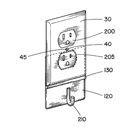
o Referring to Figure 10, there is illustrated in perspective view, a
fifth coverplate storage device 10. There is a coverplate 30, coverplate screw
slot 40, screw 45, plug receptacle 200. The coverplate storage device 10
includes a backing 120, ridge 130, plug receptacle slot 205 and hook 210.
In operation, the coverplate storage device 10 is installed by
loosening the screw 45 and coverplate 30, sliding the backing 120 under the
coverplate 30 and aligning the plug receptacle slot 205 around the lower plug
receptacle 200. The screw 45 is then reinserted and passed through the
coverplate screw slot 40 and screwed into the screw receptacle underneath
(not shown) and retightened. Variations of the fifth coverplate storage device
include the use of the screw in the coverplate as an additional securing
means for the coverplate storage device, as well as the use of both or only
one of the upper and lower plug receptacles as a securing means for the
coverplate storage device.
The coverplate storage devices and wall guard described
above, contemplate the addition of storage features to existing standard
coverplates at home or in commercial settings. However, the features
described in these coverplate storage devices and wall guard, may all be
incorporated directly into a coverplate. The modified coverplate would then
be installed like any other standard coverplate by lining up to the screw
CA 02206814 1997-06-03
receptacles and screwing in by screws. Such a modified coverplate may
have hooks molded or attached directly to the coverplate and even an
extended piece to act as a wall guard.
It is understood that the invention as described herein could be
manufactured by several methods and, in particular, it is noted that the
storage devices of the present invention may be manufactured by injection
molding.
Other variations and modifications of the invention are possible.
All such modifications or variations are believed to be within the sphere and
scope of the invention.
- 10-