Note: Descriptions are shown in the official language in which they were submitted.
CA 02206858 1997-OS-30
SELF-CLEANING BAR SCREEN FOR STORM WATER AND THE LIKE LARGE
WATER VOLUMES
FIELD OF THE INVENTION
The present invention relates to a self-cleaning bar
screen for storm water and the like large water volumes
carrying solids or suspended matters.
BACKGROUND OF THE INVENTION
It is known to provide a self-cleaning screen that
is a screen which does not require any mechanical equipment as
rotating or travelling rake for periodically cleaning the same
from the solids filtered out of the water flowing through the
screen bars.
In a known construction, the bars are set at an
angle and the solids flow down the bars by gravity into a
collecting trough disposed transverse to the lower end of the
screen bars. However, it frequently happens that the solids
fail to flow down the bars and rapidly clog the screen with
the result that the screen is overpassed and the water is not
properly screened, and will require more maintenance
attention.
1
CA 02206858 1997-OS-30
OBJECTS OF THE INVENTION
It is therefore the main object of the present
invention to provide an improved self-cleaning bar screen of
the character described in which screen clogging is
eliminated.
Another object of the present invention is to
provide such a self-cleaning which is devoid of any moving
parts.
Another object of the present invention is to
provide a bar screen of the character described of very simple
and inexpensive construction, which will have a long useful
life and which does not require any attention for its
operation.
SUMMARY OF THE INVENTION
The present invention relates to a self-cleaning bar
screen for storm water and the like large water volumes.
The gist of the invention is to provide an improved
self-cleaning bar screen in which screen clogging is
eliminated.
More particularly, the invention discloses a bar
screen comprising a plurality of parallel spaced inclined bars
having an upper end and a lower end, each bar being formed
with a channel in the upstream edge face thereof, each channel
having a cross-sectional area which decreases from said upper
2
r
CA 02206858 1997-OS-30
end to said lower end of the bar.
The invention furthermore discloses the combination
of an inflow basin having a water inlet and a weir over the
top of which the water is discharged and drops into an outflow
basin, a solid collecting trough spaced from and generally
parallel to said weir and at a level intermediate the level of
said weir and the water level in said outflow basin, a bar
screen extending between said weir top and said trough and
including a plurality of inclined, spaced, parallel, straight
screen bars each having an upper end fixed to said weir top
and a lower end fixed to said trough, whereby water
overflowing said weir drops into said outflow basin between
said screen bars and while solids in said water are filtered
out by said screen bars, each bar having an upstream edge face
formed with a longitudinal channel for receiving water
overflowing said weir and discharging the same into said
trough, whereby the water flowing within said channels causes
downward movement of said solids along said upstream edge
faces of said bars and are discharged into said trough.
Preferably, the cross-sectional area of each channel
decreases from said upper end to said lower end of the bar.
Preferably, the depth of the channel decreases while
its width remains constant from the upper end to the lower end
of the bar.
Advantageously, the rate of decrease of said cross-
3
CA 02206858 1997-OS-30
sectional area of said channel is constant from said upper end
to said lower end of said bar.
Preferably, the rate of decrease of said depth is
constant from said upper end to said lower end of said bar.
Advantageously, each screen bar has a progressively
decreasing thickness from its upstream edge face to its
downstream edge face.
Preferably, each channel has a flat bottom face and
flat inner side faces.
Advantageously, the combination further includes a
lip fixed to said weir top and overhanging said inflow basin.
Preferably, the ratio of the channel width over the
bar thickness at said upstream edge face varies from 1/2 to
5/6.
BRIEF DESCRIPTION OF THE DRAWINGS
In the annexed drawings:
Figure 1 is top plan section, taken along line 1-1
of figure 2, of an installation in which the self-cleaning
screen is used for screening storm water;
Figures 2 and 3 are vertical sections taken along
lines 2-2 and 3-3 respectively of figure 1;
Figure 4 is a vertical section at an enlarged scale
taken along line 4-4 of figure 2;
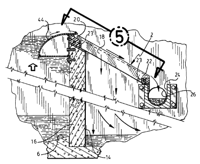
Figure 5 is a top plan view taken along line 5 of
4
CA 02206858 1997-OS-30
figure 4; and
Figures 6, 7 and 8 are sections taken along lines 6-
6, 7-7 and 8-8 respectively of figure 5.
DETAILED DESCRIPTION OF THE PREFERRED EMBODIMENT
The bar screen 2 in accordance with the present
invention is installed within a storm water screening assembly
generally indicated at 4 and comprising an inflow basin 6 fed
with rain water by an inlet pipe 8, the water network e.g.
rain storm water having a sufficient capacity to accept water
from a storm. Adjacent inflow basin 6 is a chamber 10 which
is connected by an outlet pipe 12 to the sewer network.
Inflow basin 6 is separated from an outflow basin 14 by a weir
16. Outflow basin 14 is connected to a storm water outlet
pipe 17. Bar screen 2 is composed of a series of spaced,
parallel straight screen bars 18 and intervening spacer blocks
23 secured together by tie rods (or equivalent attachment
means). Bars 18 are all coplanar and are vertically inclined,
having their upper ends 20 secured to the top of weir 16 and
their lower ends 22 secured over a trough 24 which extends
transversely of the screen bars 18 and is adapted to collect
the solids filtered out of the storm water flowing between the
screen bars 18. Trough 24 is at a level intermediate the top
of weir 16 and the maximum water level in basin 14. The
solids moving down along bars l8 are collected by the trough
5
CA 02206858 2001-10-04
24 and are directed into the chamber 10 through an opening 26 made in wall 28
separating the two basins 6 and 14 from sewer chamber 10.
In normal condition, the rate of flow of the water entering inflow basin 6
through storm water inlet pipe 8 is not sutl dent to flow over weir 16. It
simply enters a
flow regulator 30 through the regulator inlet 32 at the bottom of inflow basin
6. The flow
regulator discharges the water directly into the sewer chamber 10. The flow
regulator is
adjusted so that it controls the flow to an amount which is not above the flow
capacity of
the sewer network outlet pipe 12.
Whenever the flow rate of the water entering inflow basin 6 through inlet
1 o pipe 8 exceeds the controlled flow rate of the regulator, the water level
within inflow basis
6 rises and the water flows over the top of weir 16 onto the upstream edge
faces 34 of the
screen bars 18. The water flows between the bars to be discharged to a river
on the like by
the storm water outlet pipe 17.
The solids filtered out of the storm water and resting on the upstream edge
faces 34 of the screen bars 18 move down by gravity along the screen bars to
be collected
within the through 24. In order to assist the solids in their downward
movement towards
the trough, the upstream edge faces 34 of each bar is provided with a
longitudinally
extending
6
CA 02206858 1997-OS-30
channel 36 opening at both the upper end 20 and lower end 22
of the bar 18. A portion of storm water flowing over the top
of weir 16 enters the channels 36 and flows down these
channels to be discharged into trough 24. It has been found
that a downward moving water film is formed on the upstream
edge faces 34 of the bars effectively carrying the screened
solids into trough 24 therefore continuously effecting
cleaning of the bar screen 2.
The water flowing down channels 36 serves also to
transport the screened solids along trough 24 into sewer
chamber 10.
In one embodiment, as shown in cross-section in
figures 6 and 7, each channel 36 is of generally quadrangular
cross-section defining straight parallel inner walls 38 and a
straight bottom face 40. In an alternate embodiment (not
shown), straight bottom face 40 could be made transversely
concave to form a rounded surface merging with the straight
inside faces 38.
Preferably, the cross-sectional area of each channel
36 progressively decreases along the screen bar 18 from its
upper end 20 to its lower end 22 so that the channel will
remain filled with water along its entire length despite the
fact that the water accelerates down the channel 36 due to the
inclination of the screen bars 18. In practice, this
progressively decreasing cross-sectional area is obtained by
7
CA 02206858 1997-OS-30
progressively decreasing the depth of the channel 36, as
clearly shown in figure 8.
The pitch between adjacent screen bars 18 may vary
in accordance with the fineness of the solids to be filtered
out, this pitch being indicated as a variable pitch PV in
figure 6. This pitch is naturally composed of the maximum
thickness of each bar plus the width of the interbars slots
indicated at BV at figure 6, which is also variable. The
height of each screen bar 18 together with its thickness will
depend on the length of the screen bars 18 from the upper to
the lower supported ends 20, 22. The width A of each channel
36 may vary and, as shown in figures 6 and 7, the depth of the
channel indicated at A' in section 6-6 of the screen bars 18
is about twice the channel depth in the area of the screen
bars taken along line 7-7 of figure 5 and indicated as A'/2.
Preferably, each screen bar 18 is downwardly
tapered, as indicated by angle a from its upstream edge face
34 to its downstream edge face 35. This facilitates clearing
of the debris which might become trapped between the inter-bar
slots 42.
Screen bars 18 are preferably extruded from a
thermoplastic such as the Delrin P acetal resin sold by
Dupont.
Preferably, as shown in figure 4, the top edge of
weir 16 is fitted with a lip 44 which extends inwardly over
8
CA 02206858 1997-OS-30
the inflow basin 6. It has been found that this lip 44 acts
as a baffle or deflector which, in high water flow over the
weir, prevents the water from shooting high over the weir 16
and land on the screen bars 18 in a zone spaced a substantial
distance form their upper ends 20 so that all the upper
portion of the bar screen will remain useless for filtering.
With the lip 44, the water is caused to flow outwardly from
the weir 16 then over the curved top of the lip to fall
immediately adjacent the upper ends 20 of the screen bars 18.
Thus the entire surface of the bar screen is effective for
screening solids of the storm water.
The width A of the channels 36 may vary between 1/2
and 5/6 of an inch. The following are typical dimensions of
the screen bars 18 in relation to their maximum bar thickness
and the width of their channels 36:
:>:;::;::.:::;~::::~.~:...........e v:e>:v::>:e:>:<::...:: ..
....... y.,::.:. ;; .. . .. : ... .........: :.;:::: :.
.... ... ... .. ... : :;:.;;.:>:<......:: . ; .: ::::::.
::::.:_:::::::::>;:::::::::
w ................ .........~~a~.l.::.~
................... ~ t~.~~~e~s~s:.... : ..............
... ....................... .
...............................................................................
................................... .............. ... .. ...
. .~d~~...~.................
...........
::::: :. : ..:.::: ::. .:...
::~:~::::::::-:::~:::::~:::::::::::::::::.:.:...:::.:::::::..:...:.....
;:;:;::.::.::.:..::::...:.::...;:::...;:..:.::.::;..:
:~~~~:...::::::::::::::::::::::~::::::. ::::::::::::::::;::::::.
<:.::::::::.:::
.........:::..::............................:. .
..::................::........:::..:::..>:
.......... :..........................::::::::::;:::..:::
. . .. ..........:............................
.......................................~.........:.....................:.:.~.::
:::::::::::::::: .~~r~.... ~.~~~s. .. .:...............
:::.::.::.:.::..... ................
...............................................................................
......... ..................................
.. .... ..................................
......................................
.................................~...................................~.........
............................
1/8 1/16
3/16 1/8
1/4 3/16
3/8 1/4
9
CA 02206858 1997-OS-30
1/2 1/4
3/4 5/8
From this table, it is seen that the ratio of the
channel width over the maximum bar thickness varies from 1/2
to 5/6. Obviously, for maximum bar self-cleaning efficiency,
the ratio should be maximum.
The width of the interbar slots 42 is
preferably 1/4 of an inch, but will vary in accordance with
the size of the solids to be removed from the water.
The preferred inclination of the bar screen 2 is
between 30° and 45°. However, it is possible to vary the
inclination between 15° to 75 °.
Whenever is mentioned the word basin, it is
envisioned to include any duct, conduit or other reservoir or
tank capable of holding and retaining a volume of liquid,
particularly water. Moreover, it is noted that the
application of the present invention is not to be exclusively
limited to the sewer waste water treatment industry, but could
easily be expanded to other suitable industries, in particular
the pulp and paper industry and the food processing industry.