Note: Descriptions are shown in the official language in which they were submitted.
CA 0220701~ 1997-0~-22
r J - 1 -
The present invention is based on Japanese Patent
Application No. 8-128224 filed May 23, 1996, the content of
which is incorporated hereinto by reference.
- TITLE OF THE INVENTION
FLUID-FILLED ELASTIC MOUNT HAVING ORIFICE PASSAGES
TUNED TO DAMP INPUT VIBRATIONS IN RESPECTIVE DIFFERENT
FREQUENCY RANGES
BACKGROUND OF THE INVENTION
Field of the Art
The present invention relates to a fluid-filled
elastic mount which exhibits vibration damping and isolating
characterist~cs based on flows of a fluid contained therein,
and which elastic mount is suitably used as an engine mount
adapted to mount a power unit of a motor vehicle on a
suitable support member of the vehicle in a vibration
damping manner. More particularly, the invention is
concerned with such a fluid-filled elastic mount which is
capable of providing different vibration damping and
isolating characteristics by changing operating states of
three orifices tuned to respective frequency ranges.
Discussion of the Related Art
As one type of a vibration damper interposed
between two members of a vibration damping system, there is
known a fluid-filled elastic mount which includes a first
and a second mounting member elastically connected to each
CA 0220701~ 1997-0~-22
-- 2
other by an elastic body, a pressure-receiving chamber which
is partially defined by the elastic body and which receives
vibrations applied to the elastic mount, a variable-volume
equilibrium chamber which is partially defined by a flexible
diaphragm and whose volume is variable by displacement of
the flexible diaphragm. The pressure-receiving and
equilibrium chambers are filled with a suitable
non-compressible fluid, and communicate with each other by a
first orifice passage. The elastic mount further has a
movable member disposed between the pressure-receiving and
e~uilibrium chambers such that the movable member is
displaceable or deformable by a predetermined amount. The
elastic mount permits relative volume changes of the
pressure-receiving and equilibrium chambers based on the
1~ displacement or deformation of the movable member. This type
of fluid-filled elastic mount is capable of exhibiting a
high damping or isolating effect with respect to vibrations
applied between the first and second mounting members, based
on flows or resonance of the fluid which is forced to flow
through tne first orifice passage, while reducing or
el;m;nAting, based on the displacement or deformation of the
movable member, a considerable increase in the dynamic
spring constant upon application of the vibration in a high
fre~uency range where the first orifice passage is
2~ substantially closed. Thus, the fluid-filled elastic mount
constructed as described above is suitably used as an engine
mount for a motor vehicle, for instance.
CA 0220701~ 1997-0~-22
.3
~enerally, the elastic mount such as the engine
mount is required to exhibit different damping or isolating
characteristics depending upon the type of the input
vibrations having different frequency values and amplitudes.
For instance, the engine mount for the motor vehicle is
required to exhibit damping effects with respect to the
medium-frequency vibrations of several tens of Hz such as
idling vibrations applied to the engine mount during the
idling of the vehicle while the vehicle is in a stop with
~~ the engine in an idling state. At the same time, the engine
mount is re~uired to exhibit damping effects with respect to
the low-frequency vibrations such as engine shakes, and the
high-frequency vibrations such as booming noise, which
low-frequency and high-frequency vibrations are applied to
the engine mount during running of the vehicle.
To meet the re~uirements as described above, a
publication No. 5-40638 of Japanese Utility Model
application discloses an elastic mount including a second
orifice passage which permits a fluid communication between
the pressure-receiving and e~uilibrium chambers therethrough
and which is formed in parallel with the first orifice
passage, and a third orifice passage formed between the
movable member and the equilibrium chamber. In this elastic
mount, the second orifice passage is tuned to the frequency
range which is higher than the frequency range to which the
first ori~ice passage is tuned while the third orifice
passage is tuned to the frequency range which is higher than
CA 0220701~ 1997-0~-22
-- 4
the frequency range to which the second orifice passage is
tuned. The second and third orifice passages are selectively
controlled to be operative for the fluid communication
between the two chambers by means of a switching valve. That
is, when the second orifice passage is closed by the
switching valve for inhibiting the fluid communication
therethrough, the third orifice passage is rendered
operative by the switching valve for permitting the fluid
communication therethrough, so as to provide the damping
effect with respect to the engine shakes based on the fluid
flows through the first orifice passage as well as the
damping effect with respect to the engine booming noises
based on the fluid flows through the third orifice passage.
When the third orifice passage is closed by the switching
valve for inhibiting the fluid communication therethrough,
the second orifice passage is rendered operati~e by the
switching valve for permitting the fluid communication
therethrough, so as to assure the damping effect with
respect to the engine idling vibrations based on the fluid
~~ flows thro~gh the second orifice passage.
In view of a recently increasing requirement for
improved smooth running stability of the vehicle, there has
been a demand for further improved damping or isolating
characteristics of the engine mount. In particular, the
engine mount is required to exhibit significantly improved
damping or isolating characteristics with respect to the
engine idling vibrations in order to m;n;m; ze the vibrations
CA 0220701~ 1997-0~-22
-- 5 --
and noise while the vehicle is stationary with the engine
placed in its idling state.
SUMMARY OF THE INVENTION
It is therefore an object of the present invention
to provide a fluid-filled elastic mount having a novel
structure, which elastic mount is capable o~ exhibiting
excellent damping and isolating effects with respect to the
input vibrations over a wide fre~uency range, and suitably
used as an engine mount for a motor vehicle for assuring
excellent damping and isolating effects with respect to
engine shakes and booming noises generated during running of
the vehicle while, at the same time, exhibiting improved
damping or isolating effects with respect to engine idling
vibrations generated while the vehicle is in a stop with the
engine placed in its idling state.
The above object may be achieved according to the
principle of the present invention, which provides a
fluid-filled elastic mount comprising: a first and a second
mounting member which are spaced apart from each other; an
elastic body elastically connecting the first and second
mounting members and partially defining a pressure-receiving
chamber which receives an input vibrational load and which
is filled with a non-compressible fluid; a flexible
diaphragm which partially defines an e~uilibrium chamber
filled with the fluid, the flexible diaphragm being
displaceable to permit a change in volume of the e~uilibrium
CA 0220701~ 1997-0~-22
chamber; means for defining a first orifice passage for
effecting fluid communication between the pressure-receiving
and equilibrium chambers, the first orifice passage being
tuned to a first frequency range; a movable member disposed
between the pressure-receiving and the equilibrium chambers,
the movable member being displaceable or deformable so as to
permit relative volume changes of the pressure-receiving and
the equilibrium chambers; means for defining a second
orifice passage and a third orifice passage formed between
the movable member and one of the pressure-receiving and the
e~uilibrium chambers for permitting fluid flows therethrough
based on displacement or deformation of the movable member,
the second orifice passage being tuned to a second frequency
range which is higher than the first frequency range while
the third orifice passage is tuned to a third frequency
range which is higher than the second fre~uency range; and
first control means for permitting or inhibiting the fluid
flows through the third orifice passage.
The fluid-filled elastic mount constructed as
described above is capable of exhibiting effective damping
characteristics based on the fluid flows through the first
orifice passage as well as excellent damping characteristics
based on the fluid flows through the third orifice passage
when the third orifice passage is open for permitting the
fluid communication therethrough. Further, when the third
orifice passage is closed for inhibiting the fluid
communication therethrough, the elastic mount exhibits
CA 0220701~ 1997-0~-22
-- 7
effective damping characteristics based on the fluid flows
through the second orifice passage as well as excellent
damping characteristics based on the fluid flows through the
first orifice passage. In other words, the first, second and
third orifice passages are tuned to respective frequency
ranges by adjusting the cross sectional area and length of
each orifice passage. The second orifice passage which is
tuned to a middle frequency range has a smaller fluid flow
resistance than the first orifice passage which is tuned to
a low frequency range. The third orifice passage which is
tuned to a high fre~uency range has a further smaller fluid
flow resistance than the second orifice passage. Further,
the amounts of the fluid flowing through the second and
third orifice passages are respectively restricted by the
movable member. Accordingly, while all of the first, second
and third orifice passages are open, the fluid is forced to
flow through the third orifice passage having the smallest
fluid flow resistance as well as through the first orifice
passage in which the amount of flow of the fluid is not
restricted. On the other hand, while the third orifice
passage is closed and the first and second orifice passages
are open, the fluid is forced to flow through the second
orifice passage having a smaller fluid flow resistance than
the first orifice passage as well as through the first
orifice passage in which the amount of flow of the fluid is
not restricted.
CA 0220701~ 1997-0~-22
-- 8
The movable member disposed between the
pressure-receiving and equilibrium chambers may have any
known structure provided that it limits the amount of the
fluid flows between the pressure-receiving and equilibrium
chambers while it permits relative volume changes of the two
chambers so as to allow substantive fluid flows therebetween
by a predetermined amount. For instance, the movable member
may be in the form of a movable plate which permits relative
volume changes of the pressure-receiving and equilibrium
chambers on the basis of displacement thereof, or a flexible
plate which permits relative volume changes of the two
chambers on the basis of deformation thereof.
In a first preferred form of the invention, the
fluid-filled elastic mount further comprises second control
means for inhibiting fluid flows through the second orifice
passage when the first control means permits the fluid flows
through the third orifice passage, while the second control
means permits the ~luid flows through the second orifice
passage when the first control means inhibits the fluid
flows through the third orifice passage.
According to the arrangement as described above,
the second orifice passage is controlled to be inoperative
by the second control means while the third orifice passage
is open for permitting the fluid communication therethrough,
to thereby stably assure sufficient amounts of the fluid
flows through the third and first orifice passages. Thus,
the present elastic mount exhibits excellent damping and
CA 0220701~ 1997-0~-22
~ ~ _ g _
isolating characteristics based on the fluid flows through
the first and third orifice passages when the second orifice
passage is closed.
In a second preferred form of the invention, the
fluid-filled elastic mount is used as an engine mount for a
motor vehicle which is interposed between a power unit of
the vehicle including an internal combustion engine and a
support member of the vehicle such that the power unit is
supported by the support member via the engine mount in a
10 vibration damping manner, the second and first orifice
passages being tuned to damp respective different components
of engine idling vibrations of the power unit, such that a
component of the engine idling vibrations whose vibration
level is the highest is damped by the fluid flows through
15 the second orifice passage and such that another component
of the engine idling vibrations whose vibration level is
smaller than that of the component of the engine idling
vibrations damped by the fluid flows through the second
orifice passage is damped by the fluid flows through the
2~ first orifice passage.
In the conventional engine mount, the orifice
passage is tuned so that the engine mount exhibits a desired
damping characteristic with respect to the engine idling
vibration in a specific frequency range in which the
~5 vibration level is the highest. In other words, the
conventional engine mount is designed so as to adjust or
damp exclusively the component of the engine idling
CA 0220701~ 1997-0~-22
- ~n -
vibrations whose vibration level is the highest. ~owever, a
study made by the inventors of the present inventions
revealed that the conventional engine mount designed as
described above is not satisfactory in order to meet the
- demand for highly improved damping characteristics with
respect to the engine idling vibrations, for satisfying the
requirement for improved running stability of the vehicle.
Further, it was found that the elastic mount is required to
exhibit the vibration damping capability with respect to
la different components of the input vibrations which may arise
depending upon the engine type of the vehicle, as well as
- the component of the input vibrations whose vibration level
is the highest.
In view of the above, the elastic mount
constructed according to the above second preferred form of
the present invention is capable of adjusting or damping not
only the component of the engine idling vibrations whose
vibration level is the highest, but also the other component
or components, to thereby exhibit a considerably high
damping or isolating effect over a wider fre~uency range of
the engine idling vibrations, based on the fluid flows
through the first and second orifice passages.
The different components of the engine idling
vibrations correspond to different ratios of the vibration
frequency with respect to the rotating speed of the
crankshaft of the engine. Preferably, the first and second
orifice passages are tuned to adjust the respective
CA 0220701~ 1997-0~-22
different components of the engine idling vibrations whose
vibration levels are the highest and the second highest.
More specifically described, the first and second orifice
passages are desirably tuned to adjust the second-order
component and the first- or ~ourth-order component of the
idling vibrations generated by an in-line 4-cylinder engine,
or the third-order and the 1.5th- or sixth-order component
of the idling vibrations generated by a v-type 6-cylinder
engine. The tuning o~ the orifice passages may be
1~ advantageously ef~ected by adjusting the length and cross
sectional area of each orifice passage so as to permit the
elastic mount to exhibit a low dynamic spring constant in
the inten~ed fre~uency ranges of the input vibrations to be
damped based on the fluid flowing through the orifice
passages while taking account of the spring stiffness of the
wall of the elastic body which partially defines the
pressure-receiving chamber, and the specific gravity of the
fluid contained in the fluid chambers.
In the present elastic mount according to the
above-desc~ibed second preferred form of the invention, the
first orifice passage is tuned so as to to exhibit a
sufficiently low dynamic spring constant with respect to the
component of the engine idling vibrations which is lower
than the component of the engine idling vibrations to which
the second orifice passage is tuned. This arrangement
permits the elastic mount to exhibit an effective damping
capability with respect to the low-frequency vibrations such
CA 0220701~ 1997-0~-22
- 1 2
as engine shakes during running of the vehicle based on the
fluid ~lows through the first orifice passage.
In a third preferred form of the invention, the
third orifice passage has an open end open to the
equilibrium chamber, and the first control means comprises
pressing means for selectively placing the flexible
diaphragm in an open position in which the flexible
diaphragm is spaced apart from the open end of the third
orifice passage to permit the fluid flows through the third
orifice passage, and a closed position in which the flexible
diaphragm closes the open end to inhibit the fluid flows
through the third orifice passage.
According to this arrangement, the first control
means can be made simple in construction without requiring
the components thereof incorporated within the equilibrium
chamber, to thereby assure a simplified structure and
improved production efficiency of the elastic mount.
The pressing means may include motor-driven
mec~ni.cm for moving the flexible diaphragm toward and away
from the open end of the third orifice passage. In one
advantageous arrangement of the above third preferred form
of the invention, however, the pressing means includes: an
abutting member which is disposed on one of the opposite
sides of the flexible diaphragm remote from the e~uilibrium
chamber such that the abutting member is displaceable toward
and away from the open end of the third orifice passage;
biasing means for biasing the abutting member toward the
CA 0220701~ 1997-0~-22
- 13 -
open end of the third orifice passage such that the abutting
member forces the flexi~le diaphragm into the closed
position for inhibiting the fluid ~lows through the third
orifice passage; and means for defining an air chamber which
is formed on one of the opposite sides of the abutting
member remote from the flexible diaphragm and which receives
a negative pressure for retracting the abutting member away
from the open end of the third orifice passage against a
biasing force of the biasing means, so as to place the
flexible diaphragm in the open position for permitting the
fluid flows through the third orifice passage.
In the fluid-filled elastic mount constructed as
described above, it is not required to incorporate, within
the body of the mount, any drive means or power transmission
mechanism such as a motor for moving the abutting member
toward and away from the open end of the third orifice
passage. Thus, the pressing means can be made simple in
construction and is availabIe at a relatively low cost,
leading to reduced weight and size of the elastic mount to
2~ be obtained. When the present fluid-filled elastic mount is
used as the engine mount incorporated in the power unit of
the vehicle which includes the internal combustion engine,
the negative pressure to be applied to the air chamber for
retracting the abutting member away from the open end of the
third orifice passage can be obtained in the intake air
system of the internal combustion engine, leading to a
simplified structure of the engine mount.
CA 0220701~ 1997-0~-22
- ~4 -
In the fluid-filled elastic mount having the
pressing means as described above, the abutting member is
elastically supported at the outer peripheral portion
thereof by a sealing support rubber so that the abutting
member is displaceable under elastic deformation of the
sealing support rubber. Further, on one of the opposite
sides of the abutting member (i.e., on the side of the
~lexible diaphragm), there is formed an atmospheric chamber
which permits displacement of the flexible diaphragm while,
on the other side of the abutting member remote form the
flexible diaphragm, the air chamber is formed which receives
the negative pressure from an external negative pressure
source. When the present elastic mount is used as the engine
mount for the vehicle, the air chamber advantageously
1~ receives a negative pressure generated in the intake air
system of the internal combustion engine of the vehicle. In
this case, the sealing support rubber is desirably formed of
a material which has a high resistance to gasoline for
assuring sufficiently high durability of the sealing support
rubber.
In the fluid-filled elastic mount constructed as
described above, it is preferable to employ an elastic
member in the form of a coil spring, for instance, as the
biasing means for biasing the abutting member toward the
open end of the third orifice passage. For permitting the
elastic mount to exhibit effective damping characteristics
based on the respective fluid flows in both of the second
CA 022070l~ l997-0~-22
' - 15 -
and third orifice passages by selectively opening and
closing the third orifice passage with high stability by the
pressing means, a product Pa of an internal pressure P of
the pressure-receiving chamber which arises upon application
of the vibrational load to the mount and a cross sectional
area a of the open end of the third orifice passage is
determined to be smaller than the biasing force of the
biasing means which acts on the abutting member. (When the
coil spring is used as the biasing means, for instance, the
above-described biasing force is represented as a product kx
of a spring constant k and a compression amount x of the
coil spring measured when the coil spring is disposed in the
mount.) In addition, a product pA of a negative pressure p
to be applied to the air chamber and an effective surface
area A of the abutting member which receives the negative
pressure is determined to be larger than a force which acts
on the abutting member under a biasing action of the biasing
means upon displacement of the abutting member. (When the
coil spring is used as the biasing means for instance, the
~~ above-described force is represented as a product k(x + x')
of the spring constant k and a total compression amount x +
x' of the coil spring when the third orifice passage is open
for permitting the fluid flows therethrough (wherein, x' is
an amount of displacement of the abutting member).
2~ In a fourth preferred form of the invention, the
third orifice passage is formed between the movable member
and the equilibrium chamber, the first control means
CA 0220701~ 1997-0~-22
- 16 -
comprising: means for defining another e~uilibrium chamber
to which the third orifice passage is open and which is
formed independently of the equilibrium chamber to which the
first and second orifice passages are open; another flexible
diaphragm which partially defines the above-indicated
another equilibrium chamber to which the third orifice
passage is open; an air chamber formed on one of the
opposite sides of the above-indicated another flexible
diaphragm remote from another equilibrium chamber for
~~ permitting displacement o~ another flexible diaphragm; and
means for defining a first air passage which connects the
air chamber to a negative pressurè source for drawing
another flexible diaphragm to inhibit a change in volume of
another equilibrium chamber, to thereby substantially close
~5 the third orifice passage.
In the fluid-filled elastic mount constructed as
described above, the f irst control means for selectively
permitting and inhibiting the fluid flows through the third
orifice passage does not require any members or components
for providing drive force or biasing force to be
incorporated within the mount body, so that the elastic
mount can be made simple in construction and compact in size
while assuring improved production efficiency. When the
present elastic mount is used as the engine mount for the
motor vehicle, it effectively utilizes a negative pressure
generated in the intake air system during idling of the
vehicle, as the negative pressure to be applied to the air
CA 0220701~ 1997-0~-22
- 17 _
chamber, so as to close the third orifice passage and to
accordingly open the second orifice passage for permitting
the fluid flows therethrough. Thus, the present elastic
mount used as the engine mount stably exhibits excellent
damping or isolating characteristics with respect of the
engine idling vibrations based on the fluid flows through
the second orifice passage.
In the above fourth form of the invention, it may
be possible to permit the displacement of the flexible
diaphragm to which the third orifice passage is open by
forming the air chamber to have sufficiently large volume,
or selectively connecting the air chamber to the negative
pressure source or the atmosphere. In one advantageous
arrangement of the fourth form of the invention, however,
the elastic mount further comprise: means for defining a
second air passage for substantially connecting the air
chamber to an atmosphere; and flow restricting means for
restricting an amount of flow of the air into the air
chamber, the second air passage allowing air flows into and
from the ~ir chamber so as to permit displacement of another
flexible diaphragm when the first air passage is not
connected to the negative pressure source.
In the fluid-filled elastic mount as described
above, even if the first air passage is connected to the
negative pressure source via a conduit having a large air
flow resistance due to its small cross sectional area, the
second air passage allows the air flows into and from the
CA 0220701~ 1997-0~-22
- 18 -
air chamber, so as to permit the volume change of the air
chamber, and to accordingly permit the displacement of
another flexible diaphragm, whereby the elastic mount is
capable of exhibiting effective damping characteristics
based on the fluid flows through the third orifice passage.
While the air chamber is connected to the negative
pressure source, the ~low of the air into the air chamber is
restricted by the flow restricting means. In this
arrangement, the flexible diaphragm is effectively drawn
under vacuum and its deformation is inhibited. The ~low
restricting means may be in the form o~ a movable member
which is disposed in the second air passage such that it is
displaceable or deformable by a predetermined amount,
thereby permitting a predetermined amount of substantial air
flows between the second air passage and the air chamber,
based on the displacement or deformation of the movable
member.
When the fluid-filled elastic mount as described
above is used as the engine mount for the motor vehicle
2~ wherein the first air passage is connected to the negative
pressure source through a conduit with a vacuum valve
interposed therebetween, for instance, the conduit may have
a large air flow resistance due to the existence of the
vacuum valve. However, in the present elastic mount, while
2~ the air chamber is not connected to the negative pressure
source, the second air passage allows the air flows into and
from the air chamber, so as to permit the displacement of
CA 0220701~ 1997-0~-22
_ ~9 _
the above-indicated flexible diaphragm, whereby the present
elastic mount is capable of exhibiting effective damping or
isolating characteristics based on the fluid flows through
the third orifice passage.
BRIEF DESCRIPTION OF THE DRAWINGS
The above and optional objects, features,
advantages and technical significance of the present
invention will be better understood by reading the following
detailed description of presently preferred embodiments of
the invention, when considered in conjunction of the
accompanying drawings, in which:
Fig. 1 is an elevational view in longitl]~; n~l or
axial cross section of an engine mount constructed according
to one embodiment of the invention;
Fig. 2 is a fragmentary view in longitudinal cross
section showing a principal part of the engine mount of Fig.
1, in an operating state different from that of Fig. 1;
Fig. 3 is a view schematically showing the engine
mount of Fig. 1;
Fig. 4 is an elevational view in longitll~i n~l or
axial cross section of an engine mount constructed according
to another embodiment of the invention; and
Fig. 5 is a fragmentary view in longitll~; n~l cross
section showing a principal part of the engine mount of Fig.
,25 4.
CA 0220701~ 1997-0~-22
7 ~ ~
- 20 -
DETAILED DESCRIPTION OF THE PREFERRED EMBODIMENTS
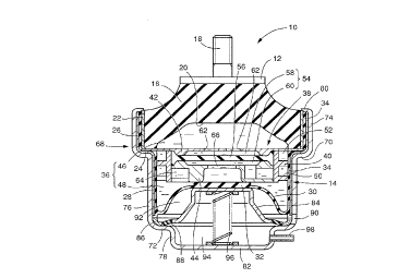
Referring first to Fig. 1, there is shown one
embodiment of a fluid-filled elastic mount in the form of an
engine mount for use on a motor vehicle constructed
according to the present invention. The engine mount
generally indicated at 10 includes a first mounting member
12 made of a metallic material, a second mounting member 14,
and an elastic body 16 which is interposed between the first
and second mounting members 10, 12 so as to elastically
connect these two mounting members 10, 12. The present
engine mount 10 is installed on the motor vehicle such that
the first mounting member 10 is attached to one of a power
unit and a body of the vehicle while the second mounting
member 12 is attached to the other of the power unit and the
vehicle body, so that the power unit is mounted on the
vehicle via the engine mount 10 in the vibration damping or
isolating manner.
When the engine mount 10 is installed on the
vehicle as described above, a load or weight of the power
unit acts on the elastic body 16, and the elastic body 16 is
elastically deformed, whereby the first and second mounting
members 10, 12 are displaced toward each other by a suitable
amount. The engine mount 10 receives a vibrational load
primarily in a direction in which the first and second
mounting members 10, 12 are opposed to each other, i.e., in
the substantially vertical direction as seen in Fig. 1. This
CA 0220701~ 1997-0~-22
-- 2 1
~irection will be referred to as "load-receiving direction"
where appropriate.
The first mounting member 12 has a generall~
circular shape. A mounting bolt 18 is secured to the ~irst
mounting member 12 so as to protrude from its central
portion in the axially upward direction o~ the engine mount
10. The elastic body 16 has a generally frustconical shape
and is formed with a recess 20 which is open in its
large-diameter end face. When the elastic body 16 is formed
in a vulcanization process, the small-diameter end face of
the elastic body 16 is bonded to the lower or inner surface
of the first mounting member 12. During the vulcanization
process, an intermediate sleeve 22 is bonded to the outer
circumferential surface of the large-diameter portion of the
elastic body 16.
The second mounting member 14 is a generally
cylindrical member having a small thickness. The second
mounting member 14 has a shoulder 24 at an axially middle
portion thereof, and includes a large-diameter cylindrical
portion 26 on the upper side of the shoulder 24, and a
small-diameter cylindrical portion 28 on the lower side of
the shoulder 24. On the lower open end of the second
mounting member 14 on the side of the small-diameter
cylindrical portion 28, there is disposed a diaphragm 30,
which is a generally thin-walled, flexible rubber layer. The
peripheral portion of the diaphragm 30 is bonded by
vulcanization to the open end of the small-diameter
CA 0220701~ 1997-0~-22
-- 2 2
cylindrical portion 28 of the second mounting member 14,
whereby the lower open end of the second mounting member 14
on the side of the small-diameter cylindrical portion 28 is
fluid-tightly closed by the diaphragm 30. The radially inner
or central portion o~ the diaphragm 30 has a larger wall
thickness than the radially outer portion thereof, so as to
provide a disc-like valve portion 32. To the inner
circumferential surfaces of the large- and small-diameter
cylindrical portions 26, 28, there are respectively bonded
by vulcanization thin sealing rubber layers 34.
The thus constructed second mounting member 14 is
~itted at its large-diameter cylindrical portion 26 on the
intermediate sleeve 22 to which the elastic body 16 is
bonded, so that the large-diameter cylindrical portion 26 of
the second mounting member 14 is secured to the outer
circumferential surface of the intermediate sleeve 22 via
the sealing rubber layer 34 by a suitable drawing operation,
for instance. Thus, the upper open end of the second
mounting member 14 on the side of the large-diameter
~~ cylindric~l portion 26 is fluid-tightly closed by the
elastic body 16. According to this arrangement, the axially
opposite open ends of the second mounting member 14 are
fluid-tightly closed by the diaphragm 30 and the elastic
body 16, respectively, so that the second mounting member 14
cooperate with the diaphragm 30 and the elastic body 16 to
define a fluid-tight space 36 filled with a suitable
non-compressive fluid such as water, alkylene glycol,
CA 0220701~ 1997-0~-22
I
- ~.3 --
polyalkylene glycol or slilicone oil. For effecti~e damping
of input vibrations based on resonance of the fluid, it is
desirable to fill the fluid-tight space 36 with a
low-viscosity fluid whose viscosity is not higher than
O.lPa s.
. Within the fluid-tight space 36 as described
above, there is disposed a partition structure 38 which is a
generally disc member with a large thickness (height
dimension in the axial direction of the engine mount 10).
The partition structure 38 is fixedly positioned with
respect to the second mounting member 14 such that it is
disposed at an axially middle portion of the ~luid-tight
space 36 so as to divide the space 36 into two sections on
the axially opposite sides thereof. The partition structure
38 consists of a generally cylindrical first partition
member 40, a generally circular second partition member 42
which is disposed on the upper end face of the first
partition member 40, and a generally annular third partition
member 44 which is fitted in a lower end portion of the
first partition member 40. The thus constructed partition
structure 38 is fixed to the second mounting member 14, such
that the first partition member 40 is fitted in the
small-diameter portion 28 of the second mounting member 14
so as to be held in abutting contact with the inner
circumferential surface of the small-diameter portion 28 via
the sealing layer 34, and such that the outer peripheral
portion of the second partition member 42 is superposed on
CA 0220701~ 1997-0~-22
- 24 -
the shoulder 24 of the second mounting member 14 and gripped
by and between the shoulder 24 and the lower end of the
intermediate sleeve 22.
The partition structure 38 divides the
fluid-tight space 36 into the two sections as described
above, i.e., a pressure-receiving chamber 46 formed on the
upper side thereof as seen in Fig. 1 and partially defined
by the elastic body 16, and an e~uilibrium chamber 48 formed
on the lower side as seen in Fig. 1 and partially defined by
the diaphragm 30. Upon application of a vibrational load to
the engine mount 10, the pressure in the pressure-receiving
chamber 46 changes due to the elastic deformation of the
elastic body 16, while the volume of the equilibrium chamber
48 is permitted to vary by displacement of the diaphragm 30.
The partition structure 38 has a spiral groove 50
spirally formed in the outer circumferential surface of the
first partition member 40. This spiral groove 50 is closed
by the small-diameter cylindrical portion 28 of the second
mounting member 14, so as to provide a first orifice passage
52 for p~rmitting fluid communication therethrough between
the pressure-receiving and e~uilibrium chambers 46, 48 based
on a pressure difference therebetween upon application of
the vibrational load to the engine mount 10.
The first partition member 40 of the partition
~5 structure 38 has a center bore which is substantially closed
by the second and third partition members 42, 44, to thereby
define an inner cavity 54. Within this inner cavity 54,
CA 0220701~ 1997-0~-22
- 25 -
there is provided a movable member in the form of a rubber
plate 56. The outer peripheral portion of the rubber plate
56 is fluid-tightly gripped by and between the second and
third partition members 42, 44, so that the rubber plate 56
divides the inner cavity 54 into an upper space 58 on the
side of the second partition member 42 and a lower space 60
on the side of the third partition member 44. The central
portion of the rubber plate 56 is elastically deformable or
displaceable in the load-receiving direction of the engine
iO mount 10. The m~imum amount of deformation or displacement
of the rubber plate 56 is determined by the abutting
contacts of the upper and lower surfaces of the rubber plate
56 with the respective second and third partition members
42, 44. The second partition member 42 which cooperates with
the rubber plate 56 to define the upper space 58 has
communication holes 62 for fluid communication between the
upper space 58 and the pressure-receiving chamber 46. The
fluid pressure in the pressure-receiving chamber 46 acts on
the upper surface of the movable rubber plate 56 through the
communica~ion holes 62. The third partition member 44 which
cooperates with the rubber plate 56 to define the lower
space 60 is formed with a second orifice passage 64 which
extends in the outer circumferential surface thereof, so as
to permit fluid communication therethrough between the lower
space 60 of the inner cavity 54 and the equilibrium chamber
48. The third partition member 44 further has a third
orifice passage 66 which is formed through its central
CA 0220701~ 1997-0~-22
~ I
- 26 -
portion for permitting ~luid communication between the lower
space 60 of the inner cavity 54 and the equilibrium chamber
48. The second and third orifice passages 64 and 66 are
formed in parallel with each other. The pressure change
generated in the pressure-receiving chamber 46 upon
application of the vibrational load to the engine mount 10
is transmitted to the upper space 58 through the
communication holes 62, so that the rubber plate 56 is
elastically deformed, whereby the fluid is forced to flow
between the lower space 60 and the equilibrium chamber 48
through the second orifice passage 64 or the third orifice
passage 66, by an amount corresponding to the amount of
elastic deformation of the rubber plate 56.
In the present embodiment, the second orifice
passage 64 has a larger ratio A/L than the first orifice
passage 52, wherein "A" and "L" represent a cross sectional
area and length of each orifice 52, 64, respectively. That
is, the second orifice passage 64 is tuned to a frequency
range higher than a fre~uency range to which the first
orifice passage 54 is tuned. Further, the third orifice
passage 66 has a larger ratio A/L than the second orifice
passage 52, so that the third orifice passage 66 is tuned to
a fre~uency range higher than the frequency range to which
the second orifice passage 52 is tuned. Described in detail,
the third orifice passage 66 is tuned so that the engine
mount 10 exhibits a low dynamic spring constant with respect
to high-frequency vibrations such as booming noises, on the
CA 0220701~ 1997-0~-22
7 ~ ~
- 27 -
basis of resonance of the fluid which is ~orced to ~low
through the third ori~ice passage 66. The second orifice
passage 64 is tuned so that the engine mount 10 exhibits a
low dynamic spring constant with respect to a second-order
component of engine idling vibrations (medium-fre~uency
vibrations) whose vibration level is the highest among
di~ferent components o~ the idling vibrations, based on
resonance of the fluid which is forced to flow through the
second orifice passage 64. The first orifice passage 52 is
tuned so that the engine mount 10 exhibits a low dynamic
spring constant with respect to a first-order component of
the engine idling vibrations (relatively low-frequency
engine idling vibrations) whose vibration level is the
second highest, as well as damping effects with respect to
1~ low-fre~uency vibrations such as engine shakes.
On the outer circumferential surface of the second
mounting member 14, there is fitted a bracket 68 through
which the second mounting member 14 is attached to the
vehicle body (not shown) via a mounting stay (not shown)
~ormed on the bracket 68.
The bracket 68 is a generally cylindrical member
which is open at its upper axial end and whlch is closed at
its lower axial end. The bracket 68 has two shoulders, i.e.,
an upper shoulder 70 and a lower shoulder 72. The two
2~ shoulders divide the cylindrical portion of the bracket 68
into three sections, i.e., an upper cylindrical portion 74
having the largest diameter, an intermediate cylindrical
CA 0220701~ 1997-0~-22
-- ~.8 --
portion 76 having the second largest diameter, and a lower
cylindrical portion 78 having the smallest diameter. The
bracket 68 further has a calking part 80 formed at an open
end of the upper cylindrical portion 74. The bracket 68 is
fitted on the second mounting member 14 in the axial
direction from the small-diameter portion 28 of the second
mounting member 14 toward the large-diameter portion 26, so
that the upper and intermediate cylindrical portions 74, 76
of the bracket 68 are fitted on the large-diameter and
small-diameter portions 26, 28 of the second mounting member
14, respectively. In this arrangement, the large-diameter
portion 26 of the second mounting member 14 and the
intermediate sleeve 22 are accommodated in the upper
cylindrical portion 74 of the bracket 68 and are axially
gripped by and between the calking part 80 and the upper
shoulder 70 of the bracket 68, whereby the bracket 68 is
fixedly attached to the second mounting member 14 so as to
surround its outer circumferential surface.
The bracket 68 has a bottom wall 82 which
cooperates with the diaphragm 30 to define an enclosed space
having a suitable volume at the bottom of the bracket 68.
Within this space, there is accommodated an abutting plate
in the form of an abutting metal member 84. The abutting
member 84 is a generally inverted-cup-shaped member having a
2~ flat, circular top wall and a cylindrical wall portion whose
diameter increases toward its open end. The peripheral
portion at the open end of the abutting member 84 is
CA 0220701~ 1997-0~-22
- 29 ~
elastically connected to and supported by a fixing ring 86
which is disposed radially outwardly of the abutting member
84, with an annular sealing support rubber 88 interposed
therebetween. The fixing ring 86 is air-tightly press-fitted
in the outer circumferential portion of the lower shoulder
7~ of the bracket 68. Accordin~ly, the abutting member 84 is
disposed in the space defined by and between the diaphragm
30 and the bottom wall 82 of the bracket 68, such that the
abutting member 84 is displaceable in the axial directions
toward and away from the partition structure 38, under
elastic deformation of the sealing support rubber 88. The
enclosed space defined by and between the diaphragm 30 and
the bottom wall 82 of the bracket 68 is air-tightly divided
by the abutting member 84 into an atmospheric cham~er 92 and
an air chamber 94, which are located on the opposite sides
of the abutting member 84. That is, the atmospheric chamber
92 formed on the side of the diaphragm 30 is brought into
communication with the atmosphere through a communication
hole 90 formed through the thickness of the
intermediate-cylindrical portion 76 of the bracket 68, so as
to permit displacement or deformation o~ the diaphragm 30.
The air chamber 94 formed on the side of the bottom wall 82
of the bracket 68 is inhibited from communicating with the
atmosphere.
Within the air chamber 94, there is accommodated
biasing means in the form of a coil spring 96. The coil
spring 96 is disposed in a compressed state between the
CA 0220701~ 1997-0~-22
- 30 -
~butting member 84 and the bottom wall 82 of the bracket 68.
In this arrangement, the coil spring 96 upwardly biases the
abutting member 84 such that the abutting member 84 forces
the valve portion 32 of the diaphragm 30 onto the central
portion of the lower surface of the partition structure 38.
Accordingly, the open end of the third orifice passage 66 on
the side of the e~uilibrium chamber 48 is fluid-tightly
closed by the valve portion 32 of the diaphragm 30, thereby
inhibiting the fluid communication through the third orifice
passage.
To the lower cylindrical portion 78 of the bracket
68, there is fixed a connecting pipe 98 which extends
through the thickness of the lower cylindrical portion 78.
The connecting pipe 98 is connected to an air conduit, which
~5 is in turn connected to a suitable negative pressure source
not shown. According to this arrangement, the air chamber 94
is selectively connected to and disconnected from the
negative pressure source. When the negative pressure is
applied to the air chamber 94 through the connecting pipe
98, the abutting member 84 is retracted downward by suction
of the negative pressure against the biasing force of the
coil spring 96, under elastic deformation of the sealing
support rubber 88, to thereby release the valve portion 32
of the diaphragm 30 from the open end of the third orifice
passage 66 formed in the partition structure 38. Thus, the
open end of the third orifice passage 66 is open to the
e~uilibrium chamber 48, to thereby permitting the fluid
CA 0220701~ 1997-0~-22
flows through the third orifice passage 66. In the present
embodiment, the abutting member 84, coil spring 96 and air
chamber 94 cooperate with each other to constitute pressing
means which controls the operating state of the third
orifice passage 66 by press}ng or retracting the diaphragm
30 toward and away from the open end of the third orifice
passage 66.
As schematically shown in Fig. 3, in the engine
mount 10 constructed according to the present embodiment,
the third orifice passage 66 is selectively opened and
closed by selectively connecting and disconnecting the
negative pressure source to and from the air chamber 94.
When the third orifice passage 66 is open, the fluid is
forced to flow through the third orifice passage 66 by an
amount which substantially corresponds to the amount of
elastic deformation of the rubber plate 56, based on the
pressure difference between the pressure-receiving and
equilibrium chambers 46, 48 caused upon application of the
vibrational load to the engine mount 1~, since the third
2~ orifice ~assage 66 has a lower fluid flow resistance than
the second orifice passage 64. At the same time, the amount
of the fluid flowing through the third orifice passage 66 is
restricted by the elasticity of the rubber plate 56 or
abutment of the rubber plate 56 with the second and third
partition members 42, 44 of the partition structure 38 which
define the inner cavity 54. Accordingly, the fluid is forced
to flow through the first orifice passage 52 on the basis of
CA 0220701~ 1997-0~-22
., . I
- 32 -
the pressure difference between the pressure-receiving and
equilibrium chambers 46, 48, which pressure difference can
not be absorbed by the elastic deformation of the rubber
plate 56.
According to the present embodiment, when the
third orifice passage 66 is open for permitting the fluid
communication therethrough, the engine mount 10 exhibits
damping effects with respect to the low-frequency vibrations
such as engine shakes owing to ~he fluid flows through the
first ori~ice passage 52 while it exhibits isolating effects
with ,respect to the high-frequency vibrations such as
booming noises owing to the fluid flows through the third
orifice passa~e 66.
On the other hand, when the third orifice passage
66 is closed for inhibiting the fluid communication
therethrough, the fluid is forced to flow through the second
orifice passage 64 by the amount substantially corresponding
to the amount of elastic deformation of the rubber plate 56,
based on the pressure difference between the
2~ pressure-receiving and equilibrium chambers 46, 48, which
pressure difference is caused upon application of the
vibrational load to the en~ine mount 10, while, at the same
time, the fluid is forced to flow through the first orifice
passage 52 based on the pressure difference between the two
2~ chambers 46, 48, which pressure difference can not be
absorbed by the elastic deformation of the rubber plate 56.
CA 0220701~ 1997-0~-22
Accordingly, when the third orifice passage 66 is
closed to inhibit the fluid communication therethrough, the
engine mount 10 exhibits damping or isolating effects with
respect to the second-order component idling vibrations
(medium-frequency vibrations) based on the fluid flows
through the second orifice passage 64, while it exhibits
effective damping or isolating effects with respect to the
first-order component idling vibrations (low-fre~uency
idling vibrations) based on the fluid flows through the
first orifice passage 52. Thus, the present engine mount 10
is capable of exhibiting excellent damping or isolating
characteristics with respect to the engine idling
vibrations.
In the engine mount 10 constructed as described
above according to the present invention, the fluid is
forced to flow through the selected one of the second
orifice passage 64 and the third orifice passage 66 while
the first orifice passage 52 is always kept to be operative
for permitting the fluid flows therethrough. Thus, by
controlling the third orifice passage 66 to be operative
during running of the vehicle, the present engine mount 10
is capable of exhibiting effective damping and isolating
effects with respect to the low-frequency vibrations such as
engine shakes and the high-frequency vibrations such as
booming noises generated during running of the vehicle.
Further, by disabling the third orifice passage 66 for
inhibiting the fluid communication therethrough while the
CA 0220701~ 1997-0~-22
,., I
- 34 -
vehicle is in a stop with the engine placed in its idling
state, the engine mount 10 is capable of exhibiting
excellent damping or isolating effects with respect to the
engine idling vibrations applied thereto during the idling
of the vehicle.
In the present engine mount 10, the third orifice
passage 66 is closed for inhibiting the fluid commllnication
therethrough by pressing the diaphragm 30 onto the open end
of the third orifice passage 66. Thus, it is not re~uired to
dispose a switching member or drive means for selectively
controlling the third orifice passage 66 to be operative and
inoperative, within the pressure-receiving chamber 46 or the
equilibrium chamber 48, thereby permitting the simplified
construction and excellent production efficiency of the
engine mount 10. Further, the diaphragm 30 is pressed onto
the open end of the third orifice passage 66 by the biasing
force of the coil spring 96, and retracted away from the
open end by the suction force based on the negative pressure
applied from the external negative pressure source.
~~ Accordingly, the present engine mount 10 assures
significantly simplified construction and improved
production efficiency, without incorporating any drive means
-or power tr~n.cm;.ssion mechanism such as an electric motor,
within the body of the engine mount 10.
2~Referring next to Fig. 4, there is shown an engine
mount 100 constructed according to a second embodiment of
the present invention. The engine mount 100 has control
CA 02207015 1997-05-22
-- 3.~ --
means for selectively permitting or inhibiting the fluid
flows through the third orifice passage 66, whlch means is
different from that of the engine mount 10 of the
above-described first embodiment. In this second embodiment,
the same reference numerals as used in the first embodiment
are used to identi~y the corresponding components and
detailed description of which is dispensed with. In the
engine mount 100 according to the second embodiment, the
diaphragm 30 and the equilibrium chamber 48 are referred to
as "first diaphragm 30" and "first equilibrium chamber 48",
respectively.
- In the engine mount 100 of the second embodiment,
the partition structure 38 has a circular central space 102
formed at the substantially central portion thereof. In this
central space 102, there is accommodated a second diaphragm
104, which is a circular thin-walled flexible layer. The
second diaphragm 104 is accommodated within the central
space 102 such that a fixing ring 105 secured by
vulcanization to the outer peripheral portion of the second
diaphragm 104 is fluid-tightly fitted in the central space
102. Thus, the cen~ral space 102 is fluid-tightly divided
into two sections by the second diaphragm 104, which are
located on the axially opposite sides of the the second
diaphragm 104.
Described more specifically, on the upper side of
the second diaphragm 104, there is formed a second
equilibrium chamber 106 to which the third orifice passage
CA 02207015 1997-05-22
- 36 -
66 is open and whose volume is variable due to elastic
de~ormation of the second diaphragm 104 so as to permit a
substantial flow of the fluid between the pressure-receiving
chamber 46 and the second equilibrium chamber 106 through
the third orifice passage 66, based on the elastic
deformation of the rubber plate 56. The second diaphragm 104
which partially de~ines the second equilibrium chamber 106
is formed separately from or independently of the first
diaphragm 30 which partially defines the first equilibrium
1~ chamber 48 to which the first and second orifice passages
52, 64 are open.
On the lower side of the second diaphragm 104 in
the central space 102, there is formed an air chamber 108
which permits the elastic deformation of the second
1~ diaphragm 104. As shown in Fig. 4, the partition structure
38 is further formed with a first air passage 110 and a
second air passage 112, each of which is brought into
communication with the air chamber 108 at the radially inner
end thereof. The second air passage 112 is formed through
the cylindrical walls of the second mounting member 14 and
the bracket 68, so as to communicate with the exterior space
at the radially outer end thereof. To the radially outer
open end of the first air passage 110, there is secured a
connecting pipe 114, which is in turn connected to an
external air conduit.
At the middle portion of the second air passage
112, there is formed a circular hollow space 116 in which a
CA 02207015 1997-05-22
-- 3 7
circular thin-walled flexible rubber layer 118 is
accommodated. This flexible rubber layer 118 is accommodated
within the hollow space 116 such that a fixing ring 120
secured by vulcanization to the outer peripheral portion of
the rubber layer 118 is air-tightly fitted in the hollow
space 116. According to this arrangement, the second air
passage 112 is air-tightly divided by the flexible rubber
layer 118 disposed in the hollow space 116 into two
sections, i.e., an upper portion which is held in
communication with the air chamber 108 and a lower portion
which is held in c~mml]n;cation with the atmosphere.
In the engine mount 100 constructed according to
the second embodiment, when the ~irst air passage 110 is not
connected to the negative pressure source as shown in Fig.
4, the second air passage 112 allows air flows into and from
the air chamber 108 based on the elastic deformation of the
flexible rubber layer 118, so as to permit displacement or
deformation of the second diaphragm 104, and accordingly
permit a change in volume of the second equilibrium chamber
106. Upon application of the vibrational load to the engine
mount lO0, therefore, the fluid is forced to flow between
the lower space 60 of the inner cavity 54 and the second
equilibrium chamber 106 through the third orifice passage
66, based on the elastic deformation of the rubber plate 56,
whereby the present engine mount 100 provides effective
damping or isolating effects as described in the first
CA 0220701~ 1997-0~-22
- 38 -
embodiment on the basis of the fluid ~lows through the third
orifice passage 66.
on the other hand, when the first air passage 110
is connected to the negative pressure source as shown in
Fig. 5, the second diaphragm 104 is drawn onto the partition
structure 38 by the negative pressure applied through the
first air passage 110. Thus, the second diaphragm 104 which
is kept drawn is prevented from de~orming, so as to inhibit
the volume change of the second e~uilibrium chamber 106. In
this condition, the fluid flow is caused neither in the
second equilibrium chamber 106 nor in the third orifice
passage 66, to thereby substantially close the third orifice
passage 66. When the vibrational load is applied to the
engine mount 100 with the third orifice passage 66 placed in
the closed state as described above, the fluid is forced to
flow through the second orifice passage 64 for fluid
communication between the lower space 60 of the inner cavity
54 and the e~uilibrium chamber 48, based on the elastic
deformation of the rubber plate 56. Accordingly, the engine
mount 100 is capable of exhibiting effective damping or
isolating effects as described with respect to the first
embodiment.
While the first air passage 110 is connected to
the negative pressure source, the second air passage 112 is
subjected to the negative pressure applied through the first
air passage 110 via the air chamber 108, so that the
flexible rubber layer 118 is drawn onto the partition
CA 02207015 1997-05-22
t
_ ~9 _
structure 38 by the applied negative pressure. Thus, the
flexible ru~ber layer 118 which is kept drawn is inhibited
~rom de~orming to inhibit the air flow into the a}r chamber
108 which would be otherwise caused by the elastic
deformation of the flexible rubber layer 118. According to
this arrangement, the second diaphragm 104 is e~fectively
kept drawn by the negative pressure as long as the first air
passage 110 is connected to the negative pressure source.
In the engine mount 100 constructed according ~o
the second embodiment of the present invention, the third
orifice passage 66 is selectively controlled to ~e
inoperative and operative for substantially inhibiting and
permitting the fluid flows therethrough, by selectively
connecting or disconnecting the air chamber 108 to and from
1~ the negative pressure source via the first air passage 110.
Thus, as in the engine mount 10 of the first embodiment, the
present engine mount 100 is capable of providing effective
damping and isolating effects with respect to the vibrations
applied thereto during running of the vehicle based on the
fluid flows through the first and third orifice passages 52,
66, as well as effective damping or isolating effects with
respect to the vibrations applied thereto while the vehicle
is in a stop with the engine in the idling state based on
the fluid flows through the first anh second orifice
passages ~2, 64.
The present engine mount 100 exhibits excellent
damping or isolating characteristics with respect to the
CA 0220701~ 1997-0~-22
- 40 -
vibrations applied thereto while the vehicle is in a stop
with the engine in the idling state, based on the fluid
flows through the first and second orifice passages 52, 64,
by application of the negative pressure to the air chamber
108 as described above. Accordingly, by utilizing a negative
pressure obtained with high stability in the intake air
system of the internal combustion engine of the vehicle
while the vehicle is in a stop with the engine placed in its
idling state, the damping or isolating characteristics of
the engine mount 100 can be changed as desired, without
re~uiring any exclusive device such as a vacuum tank for
applying the negative pressure to the engine mount 100.
The engine mount 100 of the second embodiment has
the second air passage 112 which allows the air flows into
1~ and from the air chamber 108 based on the elastic
deformation of the flexible rubber layer 118. In this
arrangement, even if the first air passage 110 is connected
to the intake air system of the vehicle having a large air
flow resistance due to provision of a vacuum switch valve
therein, for instance, the second air passage 112 readily
allows the air flows into and from the air chamber 108 while
the first air passage 110 is disconnected from the negative
pressure source, to thereby easily deform the second
diaphragm 104 for enabling the third orifice passage 66 to
function with high stability. Thus, the engine mount 100 is
capable of stably and effectively exhibiting excellent
CA 022070l~ l997-0~-22
-- 4 1
damping or isolating characteristics based on the fluid
flows through the third ori~ice passage 66.
While the present invention has been described in
its presently preferred embodiments r it is to be understood
that the invention is not limited to the details of ~he
illustrated embodiments, but may be otherwise embodied.
For instance, the configurations and structures of
the first, second and third orifice passages are not limited
to those of the illustrated em.bodiments, but may be suitably
~~ modified as needed depending on the required damping
characteristics of the fluid-filled elastic mount.
In the illustrated first embodiment, the second
and third orifice passages 64, 66 are formed between the
rubber plate 56 as the movable member and the equilibrium
chamber 48 while, in the second embodiment, the second and
third orifice passages 64, 66 are formed between the rubber
plate 56 and the equilibrium chambers 48, 106. These second
and third orifice passages may be formed between the rubber
plate 56 and the pressure-receiving chamber 46 for
permitting fluid communication therethrough between the
upper space 58 partially defined by the rubber plate 56 and
the pressure-receiving ch~mh~r 46.
The configuration and structure of the first
control means are not limited to those of the illustrated
embodiments, but may be otherwise embodied as long as it is
capable of selectively controlling the third orifice passage
to be substantially operative and inoperative for
-
CA 0220701~ 1997-0~-22
I I t
- 42 -
selectively permitting and inhibiting the fluid flows
through the third orifice passage. For instance, the first
control means may be provided with a suitable valve which is
controlled by suitable drive means, so as to open or close
the third orifice passage.
In addition to the first control means as
described in the illustrated embodiments, the fluid-filled
elastic mount may have second control means adapted to
inhibit the fluid flows through the second orifice passage
while the third orifice passage is open, and to permit the
fluid flows through the second orifice passage while the
third orifice passage is closed.
The configurations and structures of the ~irst and
second mounting members are not limited to those of the
illustrated embodiments, but may be suitably determined
depending upon the components to which the first and second
mounting members are fixed.
While the illustrated embodiments of the present
invention take the form of a fluid-filled engine mount for
an automotive vehicle, the principle of the invention is
also applicable to other types of fluid-filled elastic
mount, such as a body mount or differential mount for an
automotive vehicle, or various mounts used for e~uipment or
devices other than a motor vehicle.
It is to be understood that the present invention
may be embodied with various other changes, modifications
and improvements, which may occur to those skilled in the
CA 02207015 1997-05-22
- ~3 -
art, without departing from the spirit and scope of the
invention defined in the following claims.