Note: Descriptions are shown in the official language in which they were submitted.
CA 0220709~ 1997-06-0~
P43S0
SYSTEM AND METHOD FOR DISTINGUISHING BETWEEN
VF/VT AND BRADYCARDIA OR ASYSTOLE
BACKGROUND OF THE INVENTION
This invention relates to a system and method for defibrillation and/or
cardioversion and, more particularly, for safely determining whether or not a detected
arrhythmia has been sustained, and for avoiding delivering of an inappropriate shock
when in fact arrhythmia has not been sustained and the patient has marked
bradycardia or asystole.
The implantable cardioverter defibrillator (ICD) device has been
shown to be effective in termin~ting episodes of ventricular fibrillation (VF) and
ventricular tachycardia (VT). This capacity for detecting and termin~ting potentially
lethal ~lhyllllllias such as VF/VT has been further combined with the pacemaker
function, the combined unit being referred to as a PCD (pacemaker/cardioverter/
defibrillator) type device, such as made by Medtronic, Inc., the assignee of this
invention. The capability of this device has been further enhanced by the
development of leads for providing transvenous ventricular defibrillation. See, for
example, U.S. Patents Nos. 4,932,407 and 5,174,288, disclosing lead systems
providing transvenous ventricular defibrillation and cardioversion electrodes.
Likewise, subcutaneous defibrillation leads may be used. The PCD or ICD type
device, together with the improved leads, make it possible to provide relativelyefficient systems for termin~ting VT or VF.
A rem~ining problem with such systems for dealing with such
dangerous arrhythmias is the potential for delivering an inappropliate shock. Inparticular, this invention addresses the problem where an arrhythmia such as VT or
VF has been accurately sensed but has not been sustained. In such a situation, the
detection of VT or VF results in the system being primed to deliver a shock. If,however, the patient exhibits either marked bradycardia or asystole when the device
seeks confirm~tion of the previously detected allhyLlllllia, the lack of a sensed signal
can be taken as confirm~tion of an underlying arrhythmia, resulting in an
CA 0220709~ 1997-06-0~
p4350
ina~plopliate shock. The total number of inapl~ropl;ate shocks varies according to the
literature, but remains significant enough to be regarded as a major challenge. In
order to deal with this, ICD and PCD type devices have incorporated a variety ofreconfirm~tion algorithms, which are aimed at confirming the underlying arrhythmia
after it has been detected, thereby reducing the number of inapplopliate shocks. Of
course, the confirm~tion, or reconfirm~tion algorithm must take into account that
failure to deliver a shock when a potentially lethal arrhythmia persists cannot be
accepted; the arrhythmia confirrn~tion needs to be substantially 100 percent.
As an example of the above, in a typical PCD type device, there is a
confirm~tion period following detection of, for example, a condition of fibrillation.
This confirrn~tion period serves two purposes. First, an attempt is made to deliver
shock therapy synchronously with a patient heartbeat, when a sustained arrhythmia is
sensed. For this reason, the system may look for one or two R waves that are
consistent with the arrhythmia, and deliver a synchronous shock. However, if a
predetermined confirm~tion period expires without any sensed signal, then a shock is
delivered asychronously at the end of such period. This could likely be the correct
result, where the absence of a sensed R wave is reflective of an underlying fibrillation
or other arrhythmia. However, the time out of the confirm~tion period can also result
from the patient having reverted to marked bradycardia or asystole after a non-
sustained arrhythmia. It is clear that it is desirable to distinguish such a marked
bradycardia or asystole, i.e., a non-sustained arrhythmia, from an undersensed real
arrhythmia (VF/VT). The safe differentiation between a bradycardia episode and aVF/VT episode is desirable in order to provide delivery of a more appropriate pacing
therapy instead of an inappropriate shock.
There thus is presented a significant need for improving the
confirm~tion routine of a PCD or ICD type device, so as to avoid shock delivery
during the confirm:~tion period in the event of a bradycardia condition (e.g.,
bradycardia or asystole) after a non-sustained arrhythmia, without sacrificing the
sensitivity of arrhythmia detection and following therapy. It is also important, in
either case, to deliver the most approp~;ate and most beneficial therapy without delay:
CA 0220709~ 1997-06-0~
P4350
in the case of bradycardia or asystole after a non-sustained arrhythmia, this isappropriate anti-bradycardia pacing, while in the case of the ventricular arrhythmia
this constitutes prompt defibrillation or cardioversion therapy.
SUMMARY OF THE INVENTION
In accordance with the above need in the art, there is provided a system
and method for detecting cardiac arrhythmias such as ventricular fibrillation ortachycardia, the system having the capability following such a detection for accurately
distinguishing between a sustained arrhythmia requiring shock therapy and a non-sustained arrhythmia which is replaced by brady conditions of the sort for which only
1~ pacing therapy is desired. The system includes a PCD type unit and a suitable
electrode system such as an endocardial lead with defib and pacing electrodes. The
system continually senses cardiac signals and detects from such sensed signals an
occurrence of VT/VF. Following this, the system enters a confirm~tion sequence
where it seeks to deliver a shock in the event that sustained VF or VT is confirmed.
The confirm~tion sequence lasts for at least a predetermined brady interval, and if
arrhythmia is not positively confirmed, or a normal sinus rhythm is not detected, a
pace pulse is delivered at the time out of the confirm~tion interval. The system looks
to determine whether the delivered pace pulse has captured the heart, preferably by
ex~mining any signal sensed at the defibrillation far field electrodes, which sensed
signal is indicative of heart capture. If capture is sensed within a predetermined
interval following the pace pulse, then the system continues in a pacer mode, e.g.,
VVI pacing. However, if capture is not sensed, this verifies that the underlyingarrhythmia has been sustained and a shock is delivered at the time out of the
predetermined interval following delivery of the pace pulse. The capture detection
feature is "fail-safe" with respect to reacting to a dangerous therapy, since failure to
detect capture results in delivery of a shock.
BRIEF DESCRIPTION OF THE DRAWINGS
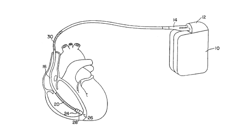
Fig. 1 is an illustration of a PCD type system according to the present
invention.
. . CA 02207095 1997-06-05
Fig. 2A is a simple timing diagram illustrating the operation of a PCD
type device embodying the present invention.
Figs. 2B and 2C are timing diagrams illustrating specific arrangements
of the confinn~tion period and follow-up capture period in accordance with this
invention.
Fig.3 is a block, functional diagram of a PCD type device adapted to
carry out the co~ tion and capture fe~L~LLes of the present invention.
Fig. 4 is a flow diagram of the logic illustrating the method of the present invention
for an episode of ventricular fibrillation.
DETAILED DESCRIPTION OF THE PREFERRED EMBODIMENTS
Refemng now to Fig. 1, there are illustrated a defibrillator 10 and a
lead 16, m~kin~ up the PCD type system of this invention. The lead shown is
illustrative, it being noted that other specific forms of leads are within the scope of
this invention. See, for example, the above-referenced U.S. Patents Nos. 4,932,407
and 5,174,288, as well as 5,261,400 . The
- lead as illustrated has, located adjacent the distal end, an e~t~n~l~kle helix electrode 26
and a ring electrode 24, the helix electrode being mounted retractably within aninsulative head 28. Electrodes 24 and 26 are utilized for bipolar cardiac pacing and
for sensing ventricular depol~ri7~tions. While electrodes 24, 26 may be used forbipolar pacing and sensing, electrode 26 may be used in conjunction with a surface of
device can 10, which surface acts as a common or indirre;lellt electrode in what is
termed unipolar operation. The lead also carries a coil electrode 20, sometimes
referred to as the RV coil, for delivering defibrillation andlor cardioversion pulses.
Electrode 20 is positioned on the lead so that when the distal tip is at the apex of the
ventricle, coil 20 is positioned in the right ventricle. Lead 16 may also carry,optionally, an SCV coil 30, positioned in the subclavian vein, which can be used for R
wave sensing and/or applying cardioversion pulses. Lead 16 carries respective
concentric coil conductors, separated from one another by al~propl;ate means such as
tubular insulative sheaths and running the length of the lead for m~kin~ electrical
66742-610
CA 0220709~ 1997-06-0
P4350
connection between the PCD device 10 and respective ones of electrodes 20, 24, 26
and 30.
An implantable PCD type device, or defibrillator 10, is shown in
combination with the lead, with the lead connector assembly 14 being inserted into
the connector block 12 of the device 10. A specific example of a defibrillation pulse
generator which may be used in conjunction with the present lead, is disclosed in U.S.
Patent No. 4,953,551. Other PCD type units can be used; reference is made to U.S.
Patents 5,163,427 and 5,188,105 as disclosing illustrative forms of apparatus for
delivering cardioversion and defibrillation pulses. As used herein, the term "PCD
type" device refers to any device which can apply both pacing therapy and shock
therapy for controlling allhyll~ ias.
Referring now to Fig. 2A, there is shown a simple timing diagram,
which illustrates the timing sequence and the primary operations of the present
invention. As shown at 32, the PCD type unit is in a detect mode, and makes a
finding of an arrhythmia (VF/VT) following a charging period. Following this at Tl,
the system sets up a confirm/sync interval 34, which is shown as being of
predetermined duration, but which may in fact be of variable duration, as discussed
further below. During the confirm/sync duration 34, the system seeks either to
confirm the arrhythmia and to deliver a synchronized shock; or time out the interval
without confirm~tion. In this simple illustration, looking for a normal sinus rhythm is
not shown. The confirm/sync interval, illustrated as T2 - Tl has a duration
corresponding to a predetermined brady escape interval, e.g., corresponding to apacing rate in the range of 60-120 bpm. When the confirm/sync escape interval runs
out at T2, a ventricular pace pulse is delivered (instead of a shock). A capture interval
is established, illustrated at 36, having a duration of about 200 ms and terrnin~ting at
time T3. During this interval the system monitors a far field signal, such as between
electrode 20 and the can 10, or between electrode 20 and SCV coil 30. If there is a
signal sensed between these far field electrodes, and the signal correlates to the
ventricular pacing stimulus, this indicates ventricular capture and is clear evidence of
a bradycardia or asystole. This conclusion follows because only in such a
CA 0220709S 1997-06-05
circurnstance is there enough myocardial mass stimulated so as to produce a signal
which can be detected as a far field signal, i.e., at electrodes displaced from the site
where the pace pulse is delivered. Following capture, the system suitably m~int~in.~ a
pacing mode. Conversely, if there is no correlation between the ventricular pacing
stimulus and the far field signal during the capture duration, this is a certain indication
of the presence of an undersensed ventricular allhylhl,lia. It is noted that in the case
of VF/VT, the myocardial mass which can be st~ tçd is too small to produce a
detectable far field signal, i.e., far field IECG. Under these circumstances, a shock of
a~propl;ate power, depending upon the nature ofthe ~ulLyLlllllia is delivered at time
T3.
Referring now to Fig. 2B, there is shown a timing diagram of a more
specific illustrative embodiment. As was the case in Fig. 2A, fibrillation (or other
ventricular allhyl~ia) is detected at time Tl. The confirm/sync duration, T 2- T l~ is
structured to include plural intervals, namely a blanlcing interval (~L) which extends
l 5 to a time Tb; a refractory interval (Ref) which extends through to time T r; a sync
interval which follows Tr and extends to time Ts; and a "normal" interval which
extends from Ts until T2. As presente~l, the timing diagram is illustrative, and the
respective durations are not nçcess~nly drawn to scale. The entire duration from Tl to
T2 constitutes a brady interval corresponding to a rate in the range of about 60-
120 bpm. Any R wave which is sensed during the blanking duration is ignored. An R
wave sensed during the refractory interval may be utilized or not, depending upon the
alg~ hLn chosen. Assuming that an R wave sensed before Tr is not used, the system
then looks for the presence of an R wave during the sync interval. An R wave that is
sensed during this sync period has come sufficiently rapidly that it is confiImed as an
arrhythrnia, and a shock is delivered in sync with such sensed R wave. However, an
R wave received after Ts but before T2 is deemed to be a normal beat and not to be an
arrhythrnia, and no shock is delivered; since such a sensed R wave is an indication of
a nonnal heartbeat, or a non-sustained ~hylh~llia, the ~lhyll~ulia is not confirmed,
and the episode is t~rmin~t~l However, if no R wave has been detected by time T2,
then a pace pulse is delivered at time T2. The pace pulse is suitably at m~il~llllll
66742-610
CA 0220709~ 1997-06-0~
P4350
available pacing output, to optimize the probability of capture. For a standard PCD
manufactured by Medtronic, Inc., this is an 8.4 volt pulse at 1.6 ms pulse width.
Following delivery of a pace pulse at T2, the system waits until time T3; it then either
confirms capture, in which case the system reverts to a pacemaker mode of operation,
or in the event of non-capture, delivers appropl;ate shock therapy.
Referring now to Fig. 2C, there is shown another timing diagram,
illustrated in relation to the timing of Fig. 2B, to illustrate another exemplary
embodiment where a first R wave is sensed during the refractory interval. In this
embodiment, the first sensed R wave causes the establishment of a second
confirm/sync interval. The difference in this embodiment is that an R wave detected
- during the first refractory interval causes a second confirm/sync interval to be timed
out, but without a refractory interval. This enables syncing on a second R wave if one
is found within the second established interval. Failure to confirm results in delivery
of a pace pulse at time T22, and delivery of a shock at time T33 if the pace pulse does
not result in capture.
Referring now to Fig. 3, there is shown a block diagram illustrating the
primary functional components of a PCD type appa.~us in accordance with this
invention. It is to be understood that the functional blocks here illustrated may be
established either with hardware, software, or a combination of haldw~ or software,
as is well known in the art. A pace generator 41, which is controlled by pace control
42, produces pacing pulses which are connected between distal electrode 26 and either
electrode 30 or can 10 for unipolar pacing (not shown); or, as shown, between
electrodes 26 and 24 for bipolar pacing. Electrodes 26 and 24 are also connected to
the input of pace/sense amplifier/processor 48, for bipolar sensing of ventricular
signals. Although not shown, bipolar sensing may also be done between electrodes 24
and 20; and unipolar sensing can be done between electrode 26 and can 10. A
cardioverter/defibrillator generator 44, which is controlled by C/D control unit 45,
provides an output illustrated as connected between RV coil 20 and SCV coil 30, or
alternately between coil 20 and the pacemaker can 10. See referenced U.S. Patent5,188,105, for an illustration of C/D control and pulse generation. Sensed R wave
CA 02207095 1997-06-05
signals are coupled at pace control 42, for norrnal control of pacing when the device is
in a pacing mode. The sensed R wave signals are also connected to VF/VT detect
block 52, for detection of the presence of an underlying VF/VT ~lhylhlllia. See U.S.
Patents Nos. 5,458,619 and 5,342,402 which
disclose generally allhyLhll~ia detection as perforrned in a PCD type device. When
VF/VT is detected, a signal is connected to block 54 to tirne out and control the
confirm/sync period. This block contains the logic for carrying out the operations as
set forth in the timing diagrams shown above. Thus, if the confirm/sync period times
out without any R wave detection, a signal is passed to pace control 42, to cause
delivery of a high level pace pulse. On the other hand, if an R wave is ~letecte~l which
is ~etermined to be part of a sequence of VT or VF, a signal is sent to C/D control
block 45, for c~ncing initiation of a C/D shock by generator 44. Control confirm/sync
block 54 also ti_es out the following capture interval, and connects the timing signals
to block 56. Block 56 is cormected to receive a far field sense signal from block 50,
which signal will be recognized at block 56 during the interval from T2 to T3. Block
56 suitably employs a binary correlator, which takes advantage of the binary ~h~r~cter
of signals and the fact that it can be implemente~l highly efflciently on a
_icroprocessor. Such binary correlators are well known in the art.
In practice, in addition to the correlator/capture block 56 which is
implemented with a microprocessor, the functions at blocks 52 and 54 are also
preferably implemented with a microprocessor and a~lopliate software algolil~
control. The rem~inin~ blocks are normally implemented by hardware, although
certainly portions of these functions, such as the pace control and C/D control may be
impl.om~nte~l by software.
Referring now to Fig. 4, there is shown a logic diagram for carrying
out the plilll~ y functions of this invention. At 60, a d~lr. ~ fion of VF/VT is made.
Following this, the PCD type unit is ~le~a~ed for delivery of a C/D shocl~, as shown
at 62. The logic then initiates time out of the confirm~tion/sync duration, as
illustrated at 63. At 64, it is deterrnined what, if anything, has happened during time
out of the confirm~tion period. If allhyl~ia is confirmed and a shock is indicated,
66742-610
CA 0220709~ 1997-06-0~
P4350
the synced shock is delivered as shown at 66. If the brady escape interval has timed
out, a pace pulse is delivered as illustrated at 68. At 70, it is determined whether there
is an indication of capture resulting from the pace pulse, within the capture duration of
around 200 ms. If yes, the shock delivery is disabled, as illustrated at 72, following
which pacing may be maintained if appropriate. If no, meaning that the pace pulse
did not capture the heart, this represents confirm~tion of the underlying arrhythmia,
and the pacer applies a C/D pulse as illustrated at 74. Returning to block 64, if a
normal sinus is detected, shock delivery is disabled.
There has thus been illustrated a PCD type system and method for
accurately detennining the presence or absence of a maintained underlying
arrhythmia, i.e., distinguishing VF/VT from marked bradycardia or asystole. By
using defibrillator (far field) electrodes to sense whether an R wave occurs which
correlates with the delivered pace pulse, the system very accurately distinguishes a
brady situation from an undersensed arrhythmia. The use of a confirm/sync periodfollowing detection of VF/VT, and limiting such period to the equivalent of a brady
escape interval, enables delivery of a synchronous shock, or an asynchronous VF/VT
shock when a~propliate and without undue delay, while also enabling a more
appropriate pacing therapy where the arrhythmia has not been m~int~ined.
As used herein, the terms "shock," "shock pulse," and "anti-arrhythmia
pulse" are used interchangeably, and refer to one or more coupled pulses delivered for
defibrillation or cardioversion. The term "far field" is used as meaning sensing the R
wave between two electrodes displaced from the site where the pace pulse is
delivered.