Note: Descriptions are shown in the official language in which they were submitted.
CA 02207206 1997-06-06
- 1 - CFO 12Z06
LIQUID DISCHARGE METHOD AND LIQUID DISCHAR~E APPARATUS
BACKGROUND OF llHE INVENTION
Field of the Invention
The present invention relates to a liquid
discharge method and a licfuid discharge apparc~tus for
discharging a clesired licfuid by generation of bubble by
thermal energy or the like and, more particulc~rly, to a
liquid discharge method and a liquid discharge
apparatus usinq a movable separation film arranged to
be displaced utilizing the generation of bubb:Le.
It is noted here that "rec,ording" in the present
invention means not only provision of an image having
meaning, such clS characters or graphics, on a recorded
medium, but also provision of an image having no
me~n; ng, such as patterns, on the medium.
Related Background Art
One of the conventionally known recordinq methods
is an ink Jet recording method for imparting energy of
heat or the like to ink so as to cause a state change
accompanied by a quick volume change of ink (generation
of bubble~, thereby discharging the ink through an
discharge port by acting force based on this state
change, and depositing the ink on a recorded medium,
thereby forming an image, which is so called ;~s a
bubble jet recording method. A recording app;~ratus
using this bubble jet recording method is normally
CA 02207206 1997-06-06
provided, as disclosed in the bulletin of Japanese
Patent Publicat.ion No. 61-59911 or in the bulletin of
Japanese Patent Publication No. 61-59914, with an
discharge port for discharging the ink, an ink flow
path in communication with this discharge port, and a
heat-generating member (an electrothermal tran.sducer)
as energy generating means for discharging the ink
located in the ink flow path.
The above recording method permits high-c[uality
images to be recorded at high speed and with l.ow noise
and in addition, because a head for carrying out this
recording method can have discharge ports for
discharging the ink as disposed in high densit;y, it has
many advantages; for example, high-resolution recorded
images or even color images can be obtained readily by
compact apparatus. Therefore, this bubble jet
recording metha,d is used in many office devices
including print;ers, copiers, facsimile machines, and so
on in recent years and further is becoming to be used
for industrial systems such as textile printing
apparatus.
On the other hand, the conventional bubb:Le jet
recording method sometimes experienced occurrence of
deposits due to scorching of ink on the surface of the
heat-generating member, because heating was repeated in
a contact state of the heat-generating member with the
ink. In the case of the li~uicl to be discharged being
CA 02207206 1997-06-06
a liquid easy to deteriorate due to heat or a liquid
not easy to generate a sufficient bubble, goocL
discharge is nct achieved in some cases by formation of
bubble by direct heating with the aforementioned heat-
generating member.
Against it, the present applicant proposed a
method for discharging an discharge liquid by
generating a bubble in a bubble-generating liquid by
thermal energy through a flexible film for separating
the bubble-generating liquid from the discharge liquid,
in the bulletin of Japanese Laid-open Patent
Application No. 55-81172. The configuration of the
flexible film cmd the bubble-generating liquid in this
method is such that the flexible film is formed in a
part of nozzle, whereas the bulletin of Japanese Laid-
open Patent Application No. 59-26270 disclose<, the
configuration using a large film for separating the
entire head into upper and lower spaces. This large
film is provided for the purpose of being placed
between two plates forming the liquid paths arLd thereby
preventing the liquids in the two liquid path~ from
being mixed wilh each other.
On the other hand, countermeasures for giving a
specific feature to the bubble--generating liquid itself
and taking bubble-generating characteristics into
consideration :include the one disclosed in the bulletin
CA 02207206 1997-06-06
of Japanese Laid-open Patent Application No. 5-229122
using a lower-boiling-point liqui~ than the boiling
point of the discharge liquid, and the one disclosed in
the bulletin of Japanese Laid-open Patent App]ication
No. 4-329148 using a liquid having electric
conductivity as, the bubble-generating liquid.
However, the liquid discharge methods us:Lng the
conventional separation film as described above are the
structure of just separating the bubble-gener~ting
liquid from the discharge liquid or simply an
improvement of the bubble-generating liquid i-tself, and
they are not at; the level of practical use yet.
SUMMARY OF THE INVENTION
The present inventors have researched mainly
liquid droplets discharged in cLischarge of liquid
droplet using t,he separation film and came to the
conclusion thal, the efficiency of liquid discharge
based on formal,ion of bubble by thermal energy was
lowered because of intervention of change of the
separation filrn, so that it had not been applied to
practical use.
Therefore" the present inventors came to study the
liquid discharqe method and apparatus that achieved the
higher level o:E liquid discharge while ta~ing advantage
of the effect by the separation function of the
separation film.
CA 02207206 1997-06-06
The present invention has been accomplished during
this study and provides breakth:rough liquid discharge
method and apparatus that are improved in the discharge
efficiency for discharge of liquid droplet and that
stabilize and enhance the volume of liquid droplet
discharged or the discharge rate.
The present invention can improve the discharge
efficiency in the liquid discharge method and apparatus
using a liquid discharging head comprising a first
liquid flow path for discharge liquid in communication
with an discharge port, a second liquid flow path
containing a bubble-generating liquid so as to be
capable of supplying or moving the bubble-generating
liquid and having a bubble-generating region, and a
movable separation film for separating the first and
second liquid flow paths from each other, and having a
region of displacement of the movable separation film
upstream of the discharge port with respect to a
direction of flow of the discharge liquid in the first
liquid flow pat;h.
Particularly, the present inventors found out the
following problem. When the space becoming the bubble-
generating region is a small space, that is, when the
bubble-generating region itself, though being formed on
the upstream side of the discharge port with :respect to
the direction of flow of the discharge liquid, has the
width and lengt,h close to those of the heat-generating
CA 02207206 1997-06-06
portion, in generation of bubble in the bubble-
generating region, the movable film is displaced with
generation of bubble only in the perpendicular
direction to the direction of discharge of the
discharge liquid, so that sufficient discharge rates
cannot be attained. This resul-ted in the proklem that
the efficient discharge operation was not achieved.
Noting that the cause of this problem is that the same
bubble-generating liquid is always used repetitively
only in the small space closed, the present ir,vention
also realizes the efficient discharge operation.
A first object of the present invention is to
provide a liquid discharge method and a liquicL
discharge apparatus employing the structure for
substantially separating or, more preferably, perfectly
separating the discharge liquid from the bubb]e-
generating liquid by the movable film, wherein in
deforming the movable film by force generated by
pressure of bubble generation to transmit the pressure
to the discharge liquid, the pressure is prevented from
leaking to upstream and the pressure is guidecl toward
the discharge port, whereby high discharge force can be
achieved without degrading the discharge efficiency.
A second object of the present invention is to
provide a liquid discharge method and a liquid
discharge apparatus that can decrease an amount of
deposits depositing on the heat-generating member and
CA 02207206 1997-06-06
that can discharge the liquid at l~igh efficien.cy
without thermally affecting the discharge liqu.id, by
the above-stated structure.
A third object of the present invention i.s to
provide a liquid discharge method and a liquid
discharge apparatus having wide freedom of sel.ection,
irrespective of the viscosity of the discharge liquid
and the formulation of material thereof.
For achieving the above objects, the preC;ent
invention provides a liquid discharge method having a
step of displac.ing a movable separation film for always
substantially separating a first liquid flow ,c)ath in
communication with an discharge port for discharging a
liquid from a second liquid flow path comprising a
bubble-generati.ng region for generating a bubble in
said liquid, on the upstream side of said discharge
port with respect to flow of the liquid in sa:d first
liquid flow pat;h,
said liqui.d discharge method comprising c~ step of
displacing a downstream portion of said movab:Le
separation film toward said discharge port re:Latively
more than an upstream portion of said movable
separation film with respect to a direction o:E the flow
of said liquid.
Here, if the above step is carried out a:Eter
midway of a growing process of bubble, a further
increase will be achieved in the discharge amount. If
CA 02207206 1997-06-06
the above step is carried out continuously
substantially after the initial stage of the growing
process of bubble, a further increase will be achieved
in the discharge rate.
The displacement of the movable separaticn film
can be controlled as desired or as stabilized by
direction regulating means for regulating the
displacement of the movable separation film in the
above step.
Specific structures for carrying out the above
displacing step, which is the fea-ture of the present
invention as described above, include those in the
embodiments described hereinafter. In addition, the
present invention involves all that can achieve the
above displacing step by other structures included in
the technological concept of the present invention.
Further, if the shape of the movable separation
film is prel; m; n~rily determined or if the movable
separation film is provided with a slack portion, the
movable separation film itself will not need t;o extend
with generation of bubble, which raises the discharge
efficiency and which permits the movable separation
film itself to regulate the displacement.
If the displacement of the movable separation film
is regulated by regulating the growth of bubb]e in the
second liquid flow path, direct action will take place
on the bubble itself, whereby the displacement of the
CA 02207206 1997-06-06
movable separation film is regula-ted from the initial
stage of generation of bubble.
Here is a typical example of the structure of the
device according to the present invention. Th.e
"direction regulating means" stated herein includes all
arrangements of the movable separation film itself (for
example, distribution of modulus of elasticity, a
combination of a deformably exten~;ng portion with a
non-deforming portion, etc.), all arrangement~' of the
second liquid flow path itself (control of the heat-
generating member or the bubble itself, etc.), an
additional member acting on the movable separation
film, structures of the first liquid flow path, and all
combinations thereof. The typical structure according
to the present invention is a liquid discharge
apparatus havin.g at least a first liquid flow path in
communication with an discharge port for discharging a
liquid, a secon.d liquid flow path comprising a bubble-
generating region for generating a bubble in said
liquid, and a movable separation film for alwclys
substantially separating said first liquid flow path
from said secon.d liquid flow path,
said liquid discharge apparatus comprisirLg
direction regulating means for displacing saicl movable
separation film on an upstream side of said discharge
port with respect to flow of the liquid in said first
liquid flow pat:h and for displacing a downstream
CA 02207206 1997-06-06
-- 10 --
portion of said movable separation film toward said
discharge port :relativel~ more than an upstream portion
of said movable separation film with respect to a
direction of the flow of said liquid.
In the present invention of the above structure,
the movable sepi~ration film provided above the bubble-
generating region is displaced into the first liquid
flow path with generation and growth of the bubble in
the bubble-generating region. On that occasian, the
downstream portion of the movable separation film is
displaced into the first liquid flow path more than the
upstream portion of the movable separation film~ so
that the pressure due to the generation of bubble is
guided toward the discharge port of the first liquid
flow path. By this, the liquid in the first liquid
flow path is discharged efficiently through the
discharge port with generation of bubble.
In the case wherein the deforming region of the
movable separation film is provided with a slack
portion, the slack portion is displaced in a curved
shape with generation and growth of bubble ancl,
therefore, the volume of the bubble acts more
effectively on deformation of the movable separation
film, thereby discharging the liquid more efficiently.
In the case wherein a movable member is provided
adjacent to the! movable separation film on the first
liquid flow pat;h side of the movable separation film
CA 02207206 1997-06-06
and wherein the movable member has a free end on the
downstream side of an upstream edge of a portion facing
the bubble-generating region an~ a fulcrum on the
upstream side of the free end, the displacement of the
movable separation film to the second liquid flow path
is suppressed upon collapse of bubble, which prevents
movement of liquid to upstream, thereby improving
refilling characteristics and decreasing crosstalk.
When the s]nape of the second liquid flow path is
one capable of readily guiding the pressure due to the
bubble generated in the bubble-generating region to the
discharge port, the liquid in the first liquid flow
path can be discharged through the discharge port
efficiently by ~eneration of bubble.
When the shape of the first liquid flow path is
such that the height is smaller upstream than
downstream, the downstream portion of the movable
separation film is displaced more into the first liquid
flow path than the upstream portion of the movable
separation film, whereby -the pressure due to the
generation of bubble is guided -to the discharge port of
the first liquid flow path, so -that the liquid in the
first liquid flow path is discharged efficiently
through the dis,-harge port by the generation cf bubble.
When the movable separation film is formed so that
the thickness thereof on the downstream side is smaller
than that on th~e upstream side, the movable separation
CA 02207206 1997-06-06
film becomes easier to deform toward the discharge port
with growth of bubble in the bubble-generating region,
whereby the liquid in the first liquid flow path is
discharged efficiently through the discharge port.
When the movable separation *ilm is provided with
a convex portion which projects into the second liquid
flow path upon non-generation of bubble and which
projects into the first li~uid flow path upon
generation of bubble, the pressure due to generation of
bubble in the bubble-generating region is guided to the
discharge port of the first liquid flow path by the
convex portion, whereby the liquid in the first liquid
flow path is discharged efficiently through the
discharge port by the generation of bubble. Further,
if the volume inside the convex portion is smaller than
the m~ximum expansion volume of the bubble generated in
the bubble-generating region, the amount of
displacement of the convex portion will be kept
constant even with dispersion in the expansion volume
of bubble due to the discharge characteristics of
liquid, thus re~lizing good discharge without
dispersion between nozzles.
BRIEF DESCRIPTION OF THE DRAWINGS
Figs. lA, lB, lC, lD and lE are cross-sectional
views along the flow path direction for explaining the
first embodied form of the liquid discharge method
CA 02207206 l997-06-06
~ - 13
according to the present invention;
Figs. 2A, ,2B, 2C, 2D and 2E are cross-sectional
views along the flow path direction for explaining the
second embodied form of the liquid discharge method
according to the present invention;
Figs. 3A, 3B, and 3C are cross-sectional views
along the flow path direction for explaining steps of
displacement of the movable separation film in the
liquid discharge method of the present invention;
Figs. 4A, 4B and 4C are cross-sectional views
along the flow path direction to show the first
embodiment of the liquid discharge method and the
liquid discharge apparatus according to the present
invention, wherein Fig. 4A is a drawing to show a state
upon non-genera-tion of bubble, Fig. 4B is a drawing to
show a state upon generation of bubble (upon
discharge), and Fig. 4C is a drawing to show a state
upon collapse of bubble;
Figs. 5A and 5B are longitudinal cross-sectional
views each to show a structural example of the liquid
discharge appari~tus of the present invention, wherein
Fig. 5A iS a drawing to show a device with a protecting
film described hereinafter and Fig. 5B is a drawing to
show a device without the protecting film;
Fig. 6 is ,~ drawing to show the waveform of
voltage applied to an electric resistance layer shown
in Figs. 5A and 5B;
CA 02207206 1997-06-06
Fig. 7 is a schematic drawing to show a structural
example of the liquid discharge apparatus according to
the present invention;
Fig. 8 is an exploded, perspective view to show a
structural example of the liquid discharge apparatus
according to the present invention;
Figs. 9A, 9B and 9C are drawings to show the
second embodiment of the liquid discharge apparatus
according to the present invention, wherein Fig. 9A is
a cross-sectional view along the flow path direction
upon non-generation of bubble, ~ig. 9B is a cross-
sectional view along the flow path direction upon
generation of bubble, and Fig. gC is a drawing obtained
by observing the first flow path from the seccnd flow
path side of the drawing shown in Fig. 9A;
Figs. lOA, lOB, lOC, lOD, lOE and lOF are cross-
sectional views along the flow path direction to show
the second embodiment of the liquid discharge method
and the liquid discharge apparatus according to the
present invention;
Figs. llA and llB are drawings to show
charact'eristics of the movable separation film used in
the liquid discharge apparatus of the present
invention, wherein Fig. llA is a drawing to show the
relation between pressure f of a bubble generated in
the bubble-generating region and stress F of the
movable separation film against i-t and Fig~ llB is a
CA 02207206 l997-06-06
- 15 -
graph to show characteristics o~ the stress F of the
movable separation film against volume change of bubble
shown in Fig. llA;
Figs. 12A ~and 12B are drawings ts show ~he fourth
embodiment of the liquid discharge apparatus according
to the present invention, wherein Fig. 12A is a cross-
sectional view along the flow path direction and Fig.
12B is a top plan view;
Figs. 13A and 13B are cross-sectional views along
the flow path direction to show the fifth embcdiment of
the liquid discharge method and the liquid discharge
apparatus accor~ing to the present invention, wherein
Fig. 13A is a drawing to show a state upon non-
generation of bubble and Fig. 13B is a drawing to show
a state upon generation of bubble (upon discharge);
Fig. 14 is a perspective view, partly brcken, of
the liquid discharge apparatus shown in Figs. 13A and
13B;
Figs. 15A, 15B, 15C and 15D are drawings for
explaining the operation of the liquid discharge
apparatus shown in Figs. 13A, 13B and Fig. 14;
Figs. 16A, 16B and 16C are drawings for explaining
the relationship of location between thick portion 205a
of movable separation film 205 and second liquid flow
path 204 in the liquid discharge apparatus shcwn in
Figs. 13A, 13B to Figs. 15A, 15B, 15C and 15D, wherein
Fig. 16A is a top plan view of the thick portion 205a,
CA 02207206 l997-06-06
- 16 ~-
Fig. 16B is a top plan view of -the second liquid flow
path 204 without the movable separation film 205, and
Fig. 1 6C is a schematic view to show the relation of
location between the thick port:ion 205a and the second
liquid flow path 204 as superimposed;
Fig. 17 is a schematic view to show a structural
example of the liquid discharge apparatus according to
the present inv,ention,
Fig. 18 is an exploded, perspective view to show a
structural example of the liquid discharge apparatus
according to th~e present invention;
Figs. l9A, l9B, l9C, l9D and l9E are drawings for
expl~;n;ng steps for producing the movable separation
film in the liquid discharge apparatus shown in Figs.
13A, 13B to Fig. 18;
Figs. 20A and 20B are cross-sectional views along
the flow path direction to show the sixth embcdiment of
the liquid discharge method and the liquid discharge
apparatus accor~ding to the present invention, wherein
Fig. 20A is a drawing to show a state upon non-
generation of bubble and Fig. 20B is a drawing to show
a state upon generation of bubble (upon discharge);
Figs. 21A, 21B, 21C and 21D are drawings for
explaining the liquid discharge method in a
modification of the liquid discharge apparatus shown in
Figs. 20A and 20B;
Figs. 22A and 22B are cross-sectional views along
CA 02207206 l997-06-06
- 17 -
the flow path direction to show the seventh embodiment
of the liquid discharge apparatus according to the
present invention, wherein Fig. 22A is a drawing to
show a state upon non-generation of bubble and Fig. 22B
is a drawing to show a state upon generation oE bubble
(upon discharge~;
Figs. 23A cmd 23B are cross-sectional views along
the ~low path direction to show the eighth embodiment
of the liquid discharge method and the liquid discharge
apparatus according to the present invention, wherein
Fig. 23A is a drawing to show a state upon non-
generation of bubble and Fig. 23B is a drawing to show
a state upon generation of bubble (upon discharge);
Figs. 24A and 24B are cross-sectional views along
the flow path direction to show the ninth embo(~iment of
the liquid discharge method and the liquid discharge
apparatus according to the present invention, wherein
Fig. 24A is a drawing to show a state upon non-
generation of bubble and Fig. 24B is a drawing to show
a state upon generation of bubble (upon discharge);
Figs. 25A, 25B and 25C are drawings to show the
tenth embodiment of the liquid discharge apparatus
according to the present invention, wherein Fiq. 25A is
a cross-sectional view along the flow path direction to
show a state upon non-generation of bubble, Fig. 25B is
a cross-sectional view along the flow path direction to
show a state upo,n generation of bubble (upon
CA 02207206 1997-06-06
discharge), and Fig. 25C is a drawing to show the
structure of the second liquid flow path;
Figs. 26A and 26B are cross-sectional views along
the flow path d:irection to show the eleventh embodiment
of the liquid discharge method and the liquid ~ischarge
apparatus accor~1ing to the present invention, wherein
Fig. 26A is a d:rawing to show a state upon non-
generation of bllbble and Fig. 26B is a drawing to show
a state upon generation of bubble (upon discharge);
Figs. 27A ;~nd 27B are cross-sectional views along
the flow path direction to show modifications of the
liquid discharge apparatus shown in Figs. 26A and 26B,
wherein Fig. 27A is a drawing to show a modification in
which a part of the second liquid flow path wall is
formed in a stepped shape and Fig. 27B is a drawing to
show a modification in which a part of the seco'nd
liquid flow path wall is formed in a curved shape;
Figs. 28A and 28B are drawings to show the twelfth
embodiment of t'he liquid discharge apparatus according
to the present invention, wherein Fig. 28A is a top
plan view to show the positional relation between the
second liquid flow path and the heat-generating member
and Fig. 28B is a perspective view of the positional
relation of Fig. 28A and wherein the discharge port is
disposed on the left side in Fig. 28A;
Figs. 29A, 29B and 29C are drawings for e,xplaining
the discharge operation in the liquid discharge
CA 02207206 1997-06-06
- 19 --
apparatus shown in Figs. 28A and 28B, wherein Fig. 29A
includes cross-<,ectional views along 29A - 29A shown in
Fig. 28A, Fig. 29B includes cross-sectional views along
29B-29B shown in Fig. 28A, and Fig. 29C includes
cross-sectional views along 29C-29C shown in Fig.
28A;
Figs. 30A, 30B and 30C are drawings to show
modifications o:E the liquid discharge apparatus shown
in Figs. 28A and 28B, wherein Fig. 30Ais a drawing to
show a modification in which the width of the second
liquid flow path near the heat-generating member
gradually increases stepwise from upstream to
downstream, Fig. 30Bis a drawing to show a
modification in which the width of the second liquid
flow path near -the heat-generating member gradually
increases in a curved shape from upstream to
downstream, and Fig. 30Cis a drawing to show a
modification in which the width of the second liquid
flow path near -the heat-generating member gradually
increases in an opposite curved shape to that of Fig.
30B from upstre~m to downstream;
Figs. 31A, 31B, 31C, 31D and 31E are drawings for
expl~; n; ng the operation of the liquid discharge
apparatus to show the thirteenth embodiment of the
li~uid discharge apparatus accoxding to the present
invention;
Figs. 32A, 32B, 32C and 32D are drawings for
CA 02207206 1997-06-06
- 20 -
explaining the relation of location among the heat-
generating member, the second liquid flow path, and a
movable separation film displacement regulating member
in the liquid discharge apparatus shown in Figs 31A to
31E, wherein Fig. 32A is a drawing to show the
positional relation between the heat-generating member
and the second liquid flow path, Fig. 32B is a top plan
view of the movable separation film displacement
regulating member, Fig. 32C is a drawing to show the
relation of location among the ~eat-generating member,
the second li~uid flow path, and the movable separation
film displacement regulating member, and Fig. 32D is a
drawing to show displaceable areas of the movable
separation film;
Fig. 33 is a cross-sectional view along the flow
path direction to show the fourteenth embodiment of the
liquid discharge apparatus according to the present
invention;
Figs. 34A, 34B, 34C and 34D are drawings for
explaining the operation of the liquid discharge
apparatus shown in Fig. 33;
Fig. 35 is a top plan view of the second liquid
flow path without the movable separation film, which is
a drawing for expl~;n;ng the structure of the second
liquid flow path in the liquid discharge apparatus
shown in Fig. 33 and Figs. 34A, 34B, 34C and 34D;
Fig. 36 is a cross-sectional view along the flow
CA 02207206 l997-06-06
- 21 -
path direction lo show the fifteenth embodimen-t of the
liquid discharge apparatus according to the present
invention, which shows a state upon generation of
bubble,
Figs. 37A, 37B, 37C and 37D are drawings for
expl~ining the operation of the liquid discharge
apparatus shown in Fig. 36;
Fig. 38 is a cross-sectional view along the flow
path direction to show the sixteenth embodiment of the
liquid discharge method and the liquid discharge
apparatus according to the present invention, which
shows a state upon generation o~ bubble;
Fig. 39 is a cross-sectional view along the flow
path direction to show the seventeenth embodiment of
the liquid discharge method and the liquid discharge
apparatus according to the present invention, which
shows a state upon generation of bubble;
Figs. 40A c~nd 40B are cross-sectional views along
the flow path direction to show the eighteenth
embodiment of the liquid discharge method and the
liquid discharge apparatus according to the present
invention, wherein Fig. 40A is a drawing to show a
state upon non-generation of bubble and Fig. 40B is a
drawing to show a state upon generation of bubble;
Fig. 41 is a cross-sectional view along the flow
path direction to show the nineteenth embodiment of the
liquid discharge method and the liquid discharge
CA 02207206 1997-06-06
apparatus according to the present invention, which
shows a state upon generation o~ bubble;
Figs. 42A ~nd 42B are cross-sectional, schematic
views along the flow path direction to show the
twentieth embod:iment of the liquid discharge method and
the liquid discharge apparatus according to the present
invention, wher~3in Fig. 42Ais a drawing to sh~w a
state upon non-(1ischarge and Fig. 42Bis a drawing to
show a state upon discharge;
Figs. 43A and 43B are cross-sectional views along
the flow path d:irection to show the twenty first
embodiment of the liquid discharge apparatus a~cording
to the present :invention, wherein Fig. 43Aisa
lateral, cross-sectional view and Fig. 43Bisa
longitudinal, cross-sectional view;
Figs. 44A and 44B are cross-sectional views along
the flow path d:irection to show the twenty second
embodiment of the liquid discharge apparatus according
to the present :invention, wherein Fig. 44Aisa
lateral, cross-sectional view and Fig. 44Bisa
longitudinal, cross-sectional view;
Figs. 45A, 45B, 45C, 45D and 45E are drawings for
explaining a process for produciny the movable
separation film shown in Figs. 44A and 44B;
Figs. 46A c~nd 46B are cross-sectional views along
the flow path direction to show the twenty third
embodiment of the liquid discharge apparatus according
CA 02207206 1997-06-06
- 23 -
to the present :invention, wherein Fig. 46A is a
lateral, cross-sectional view and Fig. 46B is a
longitudinal, cross-sectional view;
Figs. 47A, 47B, 47C, 47D and 47E are drawings for
explaining a process for producing the movable
separation film shown in Figs. ~16A and 46B;
Figs. 48A clnd 48B are drawings to show a like form
of the movable separation film shown in Figs. 46A and
46B and Figs. 47A, 47B, 47C, 47D and 47E, wherein Fig.
48A is a latera:L, cross-sectional view and Fig. 48B is
a longitudinal, cross-sectional view and wherein the
discharge port is located on the left side in the
drawing;
Figs. 49A c~nd 49B are cross-sectional views along
the flow path d-irection to show the twenty fourth
embodiment of the liquid discharge apparatus according
to the present iLnvention, where;n Fig. 49A is a
lateral, cross-sectional view and Fig. 49B is a
longitudinal, cross-sectional view;
Figs. 50A c~nd 50B are cross-sectional views along
the flow path diirection to show the twenty fifth
embodiment of the liquid discharge apparatus according
to the present iLnvention, wherein Fig. 50A is a
lateral, cross-sectional view and Fig. 50B is a
longitudinal, cross-sectional view;
Figs. 51A, 51B, 51C and 51D are drawin,gs for
explaining a process for producing the movable
CA 02207206 1997-06-06
- 24 --
separation film shown in Figs. 50A and 50B; and
Figs. 52A .~nd 52B are cross-sectional views along
the flow path direction to show an application example
wherein the present invention is applied to an
arrangement of -the discharge port disposed on the
downstream side of the bubble-generating region so that
the liquid is discharged in the direction perpendicular
to the flow direction of the liquid in the first liquid
flow path, wherein Fig. 52A iS a drawing to show a
state upon non-generation of bubble and Fig. 52B iS a
drawing to show a state upon generation of bubble.
DESCRIPTION OF THE PREFERRED EMBODIMENTS
The embodiments of the present invention will be
described, but, prior thereto, -the basic concept of
discharge, which is the basis of the present invention,
will be described with two embodied forms.
Figs. lA to lE through Figs. 3A to 3C are drawings
for explaining embodiments of the liquid discharge
method according to the present invention, wherein the
discharge port is disposed in the end area of the first
liquid flow path and wherein the displaceable area of
the movable separation film capable of being displaced
according to growth of the bubble generated i~ present
on the upstream side of the discharge port (with
respect to the flow direction of the discharge liquid
in the first liquid flow path). The second liquid flow
CA 02207206 1997-06-06
~ - 25 _
path contains the bubble-generating liquid or is filled
with the bubble--generating liquid (preferably, capable
of being refilled therewith and more preferably,
capable of moving the bubble-generating licluid) and the
second liquid flow path has a generating region of
bubble.
In the present example, this bubble-generi~ting
region is also located in the upstream area of the
discharge port with respect to the flow direction of
the discharge liquid described above. In addition, the
separation film is longer than the electrotherlnal
transducer ~orming the bubble-generating region and has
a movable area and a fixed portion, not illust:rated,
between the upst:ream edge of the electrothermaL
transducer with respect to the above flow direction and
a common liquid chamber of the first li~uid flow path,
preferably, at t;he upstream edge. Accordingly, the
substantially movable range of the separation :Eilm is
understood from Figs. lA to lE through Figs. 3A to 3C.
The states of the movable separation film in these
figures are elements representing all obtained from the
elasticity and the thickness of the movable sel?aration
film itself, or another additional structure.
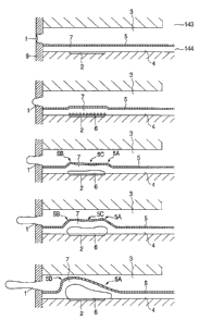
(First embodied form)
Figs. lA tc, lE are cross-sectional views along the
flow path direction for explaining the first embodied
form (an example having the displacing step of the
CA 02207206 1997-06-06
- 26 -
present invention from midway o~ the discharge step) of
the liquid discharge method according to the present
invention.
In the present form, as shown in Figs. lA to lE,
the inside of the first liquid ~low path 3 in direct
communication with the discharge port 1 is filled with
a first liquid supplied from first common liquid
chamber 143 and the second liquid flow path 4 having
the bubble-generating region 7 is filled with the
bubble-generating liquid for generating the bubble as
receiving the t~ermal energy from the heat-generating
member 2. The movable separation film 5 for separating
the first liquid flow path 3 from the second liquid
flow path 4 is provided between the first liquid flow
path 3 and the second liquid flow path 4. The movable
separation film 5 is fixed in close contact with
orifice plate 9, so that the liquids in the respective
liquid flow paths are prevented from m; X; ng herein with
each other.
When displaced by the bubble generated in the
bubble-generating region 7, the movable separation film
5 normally has no directivity or rather, the
displacement th~ereof sometimes proceeds to the common
liquid chamber with higher freedom of displacement.
In the present inven-tion, noting this motion of
the movable separation film 5, -the movable separation
film 5 itself is provided with means for regulating the
CA 02207206 1997-06-06
- 27 --
direction of displacement, acting thereon directly or
indirectly, whereby the displacement (movement,
expansion, or e~tension, or the like) of the m~able
separation film 5 caused by the bubble is directed
toward the discharge port.
In the inilial state shown in Fig. lA, the liquid
inside the first liquid flow path 3 is retracted to
near the discharge port l by capillary attraction. In
the present forrn, the discharge port l is located
downstream of the projection area of the heat-
generating member 2 onto the first liquid flow path 3
with respect to the flow direction of the liquicl in the
liquid flow path 3.
In this stc~te, when the thermal energy appears in
the heat-genera1ing member 2 (a heating resist~r member
having the shape of 40 ,um x 105 lum in the present
form), the heat--generating member 2 is heated ~uickly
and the surface in contact with the second liq-uid in
the bubble-generating region 7 heats the second liquid
to generate bubbles (Fig. lB). The bubbles 6 generated
by this heating generation of bubble are those based on
the film boiling phenomenon as clescribed in United
States Patent No. 4,723,129 and are generated together
all over the surface of the heat-generating member as
carrying very high pressure. The pressure generated at
this time propagates in the form of pressure wave in
the second liquid in the second liquid flow path 4 to
CA 02207206 1997-06-06
- 28 --
act on the movable separation film 5 thereby
displacing the ~novable separation film 5 and starting
discharge of the first liquid in the first liqlid flow
path 3.
As the bubbles 6 generated over the entire surface
of the heat-generating member 2 grow quickly they
become of a filnn shape (Fig. lC). The expansion of the
bubble 6 by the very high pressure in the init.ial stage
of generation further displaces the movable separation
film 5 which promotes discharge of the first :Liquid in
the first liquicl flow path 3 through the disch.~rge port
1.
Further growth of the bubble 6 thereafter
increases the displacement of the movable separation
film 5 (Fi~. lD~. Up to the state shown in Fig. lD
the movable separation film 5 continues extend:ing so
that displacement of upstream portion 5A becomes nearly
equal to displacement of downstream portion 5B with
respect to central portion 5C of the area of the
movable separati.on film facing the heat-generating
member 2.
After that with further growth of the bubble 6
the bubble 6 ancL the movable separation film 5 having
continuously been displaced are displaced so that the
downstream porti.on 5B is displaced relatively greater
toward the discharge port than the upstream portion 5A
whereby the first liquid in the first liquid f]ow path
CA 02207206 1997-06-06
- 29 -
3 is moved directly toward the discharge port L (Fig.
lE).
The discharge efficiency is increased fur-ther by
the step wherein the movable separation film 5 is
displaced towarcl the discharge port on the downstream
side so that the liquid is directly moved toward the
discharge port as described above. Further, movement
of the liquid to upstream is decreased relatively,
which is effective in refilling of liquid
(replenishment from upstream) into the nozzle,
especially into the displacement area of the movable
separation film 5.
When the movable separation film 5 itself is also
displaced toward the discharge port so as to change
from Fig. lD to Fig. lE, as shown in Fig. lD and Fig.
lE, the discharg~e efficiency and refilling eff:Lciency
described above can be further increased and il, causes
transport of the first liquid in the projection area of
the heat-generating member 2 in the first liquid flow
path 3 toward the discharge port, thus increasing the
discharge amount.
(Second embodied form)
Figs. 2A to 2E are cross-sectional views along the
~10w path direction for explaining the second embodied
form (an example having the displacing step of the
present invention from the initial stage) of the liquid
discharge method according to the present inverltion.
CA 02207206 l997-06-06
- 30
The presenl form also has the basically similar
structure to the first embodied form, wherein, as shown
in Figs. 2A to 2E, the inside of the first liquid flow
path 13 in direct communication with the disch;~rge port
11 is filled wilh the first liquid supplied fr~m the
first common liquid chamber 143 and the second liquid
flow path 14 having the bubble-generating region 17 is
filled with the bubble-generating liquid for generating
the bubble as receiving the thermal energy from the
heat-generating member 12. The movable separa-tion film
15 for separating the first liquid flow path 13 from
the second liquid flow path 14 is provided between the
first liquid flow path 13 and the second liquid flow
path 14. The movable separation film 15 is fixed in
close contact with the orifice plate 19, so that the
liquids in the respective liquid flow paths are
prevented from mixing herein with each other.
In the init:ial state shown in Fig. 2A, the liquid
in the first liquid flow path 13 is retracted 1o near
the discharge port 11 by capillary attraction,
similarly as in Fig. lA. In the present form, the
discharge port 11 is located on the downstream side o~
the projection area of the heat-generating member 12
onto the first liquid flow path 13.
In this state, when the thermal energy appears in
the heat-generating member 12 (a heating resislor
member having th,e shape of 40 ~m x 115 ~um in the
CA 02207206 1997-06-06
present form), the heat-generating member 12 is heated
quickly and the surface in contact with the second
liquid in the bubble-generating region 17 heats the
second liquid to generate bubbles (Fig. 2B). rhe
bubbles 16 generated by this heating generation of
bubble are those~ based on the film boiling phenomenon
as described in United Sta~es Patent No. 4,723,129 and
are generated together all over the surface of the
heat-generating member as carrying very high pressure.
The pressure generated at this time propagates in the
form of pressure wave in the second liquid in the
second liquid flow path 14 to act on the movable
separation film 15, thereby displacing the movl~ble
separation film 15 and starting discharge of the first
liquid in the first liquid flow path 13.
As the bubbles 16 generatecl over the entire
surface of the heat-generating member 12 grow quickly,
they become of a film shape (Fig. 2C). The expansion
of the bubble 16 by the very high pressure in -the
initial stage of generation further displaces the
movable separation film 15, whi~h promotes discharge of
the first liquicL in the first liquid flow path 13
through the discharge port 11. At this time, ~s shown
in Fig. 2C, the movable separation film 15 is (iLisplaced
from the initial stage so that in the movable c~rea,
displacement of the downstream portion 15B is
relatively greater than that of the upstream portion
CA 02207206 1997-06-06
- 32 -
.
15A. This efficiently moves the first liquid in the
first liquid flow path 13 toward the discharge port 11
from the beginning.
After that, with further growth of the bubble 16,
the displacemen-t o~ film 15 and the growth of bubble is
promoted from the state of Fig. 2C, and thus the
displacement of the movable separation film 15 also
increases therewith (Fig. 2D). Especially, the
downstream port:ion 15B of the movable area is displaced
greater toward 1the discharge port than the upstream
portion 15A and the central portion 15C, whereby the
first liquid in the first liquid flow path 13 is
directly accelerated to move toward the discharge port.
In addition, since displacement of the upstream portion
15A is not much during the whole process, movement of
the liquid to upstream is decreased.
Therefore, the discharge efficiency, especially
the discharge rate, can be increased and it is
advantageous in refilling oi- liquid to nozzle ;~nd in
stabilization oi- the volume of clroplet of discharge
liquid.
After that, with further growth of the bubble 16,
the downstream portion 15B and central portion 15C of
the movable separation film 15 are further displaced to
extend toward the discharge port, thereby achieving the
above-stated efiect, i.e., the increase in the
discharge efficiency and discharge rate (Fig. 2E).
CA 02207206 1997-06-06
- 33 -
Especially, in the shape of the movable separa-tion film
15 in this case, displacement and extension in the
width direction of the liquid flow path also increases
in addition to t,hat shown by the cross-section~l shape,
so that an increase of the action area takes p:Lace to
move the first ]iquid in the first liquid flow path 13
toward the discharge port, which synergisticalLy
increases the discharge efficiency. Particula:rly, the
displacement shape of the movable separation film 15 at
this time will be referred to as a nose shape, because
it is similar to the shape of human nose. Thi~ nose
shape includes the "S" shape, as shown in Fig. 2E,
wherein point B, which was located upstream in the
initial state, is located downstream of point A, which
was located downstream in the initial state, and the
shape, as shown in Fig. lE, wherein these points A, B
are located at equivalent positions.
(Form of displac,ement of the movable separation film)
Figs. 3A to 3C are cross-sectional views ;~long the
flow path direction for expl~;n;ng steps of
displacement of the movable separation film in the
liquid discharge method of the present invention.
In the present form, especially, since description
is given as focusing attention on the movable range and
the change of displacement of the movable separation
film, the bubble, the first liquid flow path, ;~nd the
discharge port are not illustrated but the basic
CA 02207206 1997-06-06
~ - 34 -
structure in eilher figure is such that the bubble-
generating regic~n 27 is near the projection area of the
heat-generating member 22 in the second liquid flow
path 24 and thal, the second liquid flow path 2~1 and the
first liquid flow path 23 are always substanti.~lly
separated from each other by the. movable separ~tion
film 25, specifically, throughout the period o:E from
the beginning to the end of displacement. Witll respect
to the border at; the downstream edge (denoted by line H
in the drawing) of the heat-generating member ;22, the
discharge port is provided on the downstream s:ide while
the supply portion of the first liquid is on the
upstream side. In this form and after, "upstream" and
"downstream" are defined based on the central portion
of the movable range of the movable separation film
with respect to the flow direction of the liqu:d in the
flow path.
The example shown in Fig. 3A has from the
beginning the step wherein the movable separat on film
25 is displaced in the order of (1), (2) and (3) in the
drawing from thel initial s-tate whereby the clownstream
side is displace,d more than the upstream side.
Especially, it ~nh~n~es the discharge efficiency and
has such action that the downstream displacement causes
such movement as to push the first liquid in the first
liquid flow path 23 toward the discharge port, thus
increasing the discharge rate. In Fig. 3A the above
CA 02207206 1997-06-06
- 35 --
movable range is substantially constant.
In the exa~ple shown in Fig. 3B, as the movable
separation film 25 iS displaced in the order of (l),
(Z) and ( 3) in the drawing, the movable range of the
movable separation film 25 moves or expands toward the
discharge port. In this form the upstream side o~ the
above movable range is fixed. In this example, since
the downstream side is displaced more than the upstream
side and since the growth of bubble itself is directed
toward the discharge port, the discharge efficiency can
be enhanced furt;hermore.
In the example shown in Fig. 3C, displacelnent of
the movable separation film 25 is such that the
upstream side and the downstream side are disp:Laced
equally or the upstream side is displaced a li1tle
larger from the initial state (l) to the state
indicated by (2) in the drawing, but with further
growth of the bubble as shown from (3) to (4) :Ln the
drawing, the downstream side is displaced more than the
upstream side. This can also move the first liquid in
the upstream part of the movable range toward 1he
discharge port, whereby the discharge efficienc,y can be
increased and the discharge amount can also be
increased.
Further, in the step indicated by in Fig. 3C,
since a certain point U on the movable separation film
25 is displaced toward the discharge port farther than
CA 02207206 1997-06-06
- 36 -
point; D, which was located downstream thereof in the
initial state, the discharge efficiency is improved
furthermore by the inflated portion projecting to the
discharge port. This shape will be called the nose
shape as described above.
The presenl invention incl~ldes the liquid
discharge methods having the steps as describe~1 above,
but it is noted that the examples shown in Figs. 3A to
3C are not always independent of each other and that
the present invention also includes steps having
components of the respective examples. The step having
the nose shape can be introduced not only to the
example shown in Fig. 3C, but also to the examples
shown in Figs. 3A ànd 3B. The movable separat:ion film
used in Figs. 3A to 3C may be preliminarily provided
with a slack portion, irrespective of whether :it has
capability of expansion and contraction. It is also
noted that the t;hickness of the movable separa1ion film
in the drawing does not have specific, ~;m~n~iona
meaning.
Embodiments
The embodiments of the present invention will be
described with reference to the drawings.
The "direction regulating means" in the present
specification is directed to at least either one of
means based on the structure or feature of the movable
separation film itself, the action or arrangement
CA 02207206 1997-06-06
~ - 37 -
relation of the bubble-generatin.g means to the movable
separation film, the flow resistance relation c~round
the bubble-generating region, a member directly or
indirectly acting on the movable separation fi m, and a
member (means) for regulating displacement or extension
of the movable separation film, and includes all for
achieving the "displacement" defined by the present
application. Accordingly, the present invention
includes embodim.ents having a plurality o~ (two or
more) the above direction regulating means, of course.
Although the embodiments described below will not show
an arbitrary combination of plural direction regulating
means clearly, it is noted that the present invention
is by no means intended to be limited to the fc,llowing
embodiments.
(Embodiment 1)
Figs. 4A to 4C are cross-sectional views a.long the
flow path direction to show the first embodimen.t of the
liquid discharge method and the liquid discharge
apparatus according to the present invention, wherein
Fig. 4A is a drawing to show the state upon non-
generation of bubble, Fig. 4B is a drawing to show the
state upon generation of bubble ~upon discharge), and
Fig. 4C is a drawing to show the state upon collapse of
bubble.
In the present embodiment, as shown in Fig. 4A,
the second liquid flow path 104 for bubble-generating
CA 02207206 l997-06-06
- 38 ~-
liquid is provided on substrate 110 provided with heat-
generating member 102 (a heating resistor member in the
shape of 40 ~um x 105 ~m in the present embodiment) for
giving the thermal energy for generating the bubble to
the liquid, and the first liquicl flow path 103 for
discharge liquid in direct communication with the
discharge port L01 is provided above it. I'he movable
separation film 105 made of a thin film with elasticity
is provided between the first liquid flow path 103 and
the second liqu:id flow path 104, so that the m~vable
separation film 105 separates the discharge liquid in
the first liqui(~ flow path 103 from the bubble-
generating liquid in the second liquid flow path 104.
The movable sepi~ration film 105 is disposed as opposed
to the heat-generating member 102 and faces at least a
part of the bubble-generating region 107 in which the
bubble is generated by heat in the heat-generating
member 102. Further provided on the first liquid flow
path 103 side of the movable separation film 105 is
movable member 131 as the direction regulating means
adjacent to the movable separation film 105, and the
movable member 131 has free end 131a above the bubble-
generating region 107 and fulcrum 131b on the llpstream
side of the free end 131a.
The free end 131a of the movable member 131 does
not always have to be located in the portion fi~cing the
bubble-generating region 107, but it may be one
CA 02207206 1997-06-06
- 39 -
provided downstream of fulcrum 131b and arranged to
guide extension of the movable separation film 105
toward the discharge port 101. More preferably, it is
opposed through the movable separation film. 105 to at
least a part of the heat-generating member 102, whereby
the displacement of the movable separation film 105 can
be controlled efficiently. Par-ticularly, if the
movable member 131 is arranged so that the free end
131a thereof is located at the position opposite to the
movable separation film 105 on the downstream side of
the center of the area of the heat-generating member
102 or the bubble-generating region 107, the movable
member 131 can make expanding components perpendicular
to the heat-generating member 102 concentrated toward
the discharge port 101, thus greatly improving the
discharge efficiency. In the case wherein the free end
131a is provided on the downstream side of the bubble-
generating region 107, the discharge efficiency is
improved, because the free end 131a is displaced more
greatly so as to displace the movable separation film
105 more toward the discharge port 101.
Now, when heat is generated in the heat-generating
member 102, the bubble 106 is generated in the bubble-
generating region 107 on the heat-generating member
102, whereby th~e movable separation film 105 is
displaced into the first liquid flow path 103. Here,
the displacement of the movable separating film 105 is
CA 02207206 1997-06-06
- 40 -
regulated by the movable member 131. Since the movable
member 131 is provided with the free end 131a aLbove the
bubble-generating region 107 and the fulcrum 131b
upstream thereof, the movable separation film :L05 is
displaced more on the downstrea~l side than on the
upstream side (~ig. 4B). Namely, the desired
deformation and displacement can be attained on a
stable basis by the direction regulating means for
regulating the direction of displacement of the movable
separation film.
In this way, with growth of bubble 106 the
downstream portion of the movable separation film 105
is displaced gre!ater, whereby the growth of bubble 106
is transmitted mLainly toward the discharge port 101, so
that the discharge liquid in the first liquid i-'low path
103 is discharged efficiently from the discharcre port
101 .
After that, the bubble 106 contracts to return the
movable separation film 105 to the position before
displacement.
In this case, the movable separation film 105 is
shifted to the second liquid flow path 104 fronl the
position before displacement by the pressure caused by
the disappearance of bubbles. However, in thi~
embodiment, the displacement of the movable separation
film 105 to the second liquid flow path is restricted
since the movable separation film 105 is integrally
-
CA 02207206 l997-06-06
~ - 41 -
provided on the movable member 131 (Fig. 4C).
Therefore, the pressure at the side of the movable
member 131 is limited to decrease so that the
retraction of the meniscus is restricted and the
re~illing properties are improved.
The movable member 131 restricts movement of the
liquid to upstream, thereby achieving the e~fec:ts
including an improvement in the refilling
characteristics, decrease of crosstalk, and so on.
As described above, the structure of the Elresent
embodiment can discharge the discharge liquid, using
the different liquids as the discharge liquid a.nd as
the bubble-generating liquid. Therefore, the ~resent
embodiment can wl~ll discharge even high-viscosity
liquid such as polyethylene glycol, which was
insufficient to !~enerate the bubble with application of
heat and which thus had insufficient discharge force
heretofore, by supplying this liquid to the first
liquid flow path 103 and supplying another liquid with
good bubble-generating property (for example, a mixture
of ethanol : water = 4 : 6 having the viscosity of
about 1 to 2 cP) as the bubble-generating liquid to the
second liquid flow path 104.
By selecting the bubble-generating liquid from
those that form no deposits of scorching or the like on
the surface of the heat-generating member with
CA 02207206 l997-06-06
- 42 -
application of heat, bubble generation can be
stabilized and good discharge can be carried out.
Further, since the structure of the liquid
discharge appar~tus according to the present invention
also achieves the effects as described in the above-
stated embodiment, the liquid such as the high-
viscosity liquid can be discharged at further higher
discharge efficiency and under further higher ejection
force.
In the case of the liquid weak against heat being
used, if this liquid is supplied as the discharge
liquid to the f:irst liquid flow path 103 and another
liquid resistan-t against therma:L deterioration and easy
to generate the bubble is supplied to the second liquid
flow path 104, -the thermally weak liquid can be
discharged at h:igh discharge efficiency and under high
discharge force as described above without thermally
damaging the liquid weak against heat.
Next expla:ined is the configuration of the element
substrate 110 in which the heat--generating member 102
for supplying heat to the liquid is mounted.
Figs. 5A and 5B show longi-tudinal, cross-sectional
views each to show a structural example of the liquid
discharge apparatus according to the present invention,
wherein Fig. 5A shows the device with a protection film
as detailed hereinafter and Fig, 5B the device withou-t
the protection :Eilm.
CA 02207206 l997-06-06
- 43 --
Above the element substrate 110 there are provided
the second liquid flow path 104, the movable separation
film 105 to be a partition wall, the movable ml~mber
131, the first :Liquid flow path 103, and a grooved
member 132 having a groove for forming the fir,st liquid
flow path 103, c~s shown in Figs. 5A and 5B.
The elemeni substrate 110 has patterned w.iring
electrodes llOc 0.2-1.0 ~m thick of aluminum (Al) or
the like and patterned electric resistance lay~3r llOd
0.01-0.2 ,um thic,k of hafnium boride (HfB2), tantalum
nitride (TaN), l,antalum aluminum (TaAl) or the like
constituting the heat-generating member on sil:icon
oxide film or silicon nitride film llOe for electric
insulation and t,hermal accumulation formed on base llOf
of silicon or the like. The resistance layer :LlOd
generates heat when a voltage is applied to the
resistance layer llOd through the two wiring e:Lectrodes
llOc so as to let an electric current flow in -the
resistance layer llOd. A protection layer llOb of
silicon dioxide, silicon nitride, or the like ().1-0.2
,um thick is provided on the resistance layer l:LOd
between the wiri.ng electrodes llOc, and in add:Ltion, an
anti-cavitation layer llOa of tantalum or the :Like 0.1-
0.6 ,um thick is formed thereon to protect the
resistance layer llOd from various liquids Such as ink.
Particularl.y, the pressure and shock wave
generated upon bubble generation and collapse Ls so
CA 02207206 1997-06-06
- 44 --
strong that the durability of the oxide film h(~rd and
relatively ~ragile is considerably deteriorated.
Therefore, a met;al material such as tantalum (rra) or
the like is usecl as a material for the anti-cavitation
layer llOa.
The protect;ion layer stated above may be omitted
depending upon t;he combination o~ liquid, liquLd flow
path structure, and resistance material, an example of
which is shown in Fig. 5B.
The material for the resistance layer not
requiring the protection layer may be, for example, an
iridium-tantalum-aluminum (Ir-Ta-Al) alloy or 1he like.
Particularly, since the present invention uses the
liquid for generation of bubble separated from the
discharge liquid and being suitable for generat;ion of
bubble, it is advantageous in the case withou~ the
protection layer as described.
Thus, the structure of the heat-genera-tinq member
102 in the foregoing embodiment may be that including
only the resistance layer llOd (heat-generating
portion) between the wiring electrodes llOc~ or may be
that including the protection layer for protecting the
resistance layer llOd.
In this embodiment, the heat-generating member 102
has a heat generation portion having the resistance
layer which generates heat in response to the electric
signal. Without having to be limited to this, any
CA 02207206 1997-06-06
- 45 -
means well suffices if it creates the bubble enough to
discharge the discharge liquid, in the bubble-
generating liqu:id. For exampler the heat generation
portion may be :in the form of a photothermal transducer
which generates heat upon receiving light such as
laser, or a heat-generating element having the heat
generation port:ion which generates heat upon receiving
high frequency wave.
Function elements such as a transistor, a cliode, a
latch, a shift register, and so on for selectively
driving the electrothermal transducer may also be
integrally buil1, in the aforementioned elentent
substrate llO by the semiconductor fabrication process,
in addition to 1he electrothermal transducer comprised
of the resistance layer llOd constituting the heat-
generating portion and the wiring electrodes llOc for
supplying the e3ectric signal to the resistance layer
llOc .
In order to drive the heat generation portion of
the electrothermal transducer on the above-described
element substrat;e llO so as to clischarge the liquid, a
rectangular pulse is applied through the wiring
electrodes llOc to the resistanc:e layer llOd to quickly
heat the resistance layer llOd between the wir:ing
electrodes llOc. Fig. 6 is a diagram to show -~he
waveform of the voltage applied to the resistarLce layer
llOd shown in Figs. 5A and 5B.
CA 02207206 1997-06-06
- 46 --
With the l:iquid discharge apparatus of the
foregoing embod:iment, the electric signal was ,~pplied
to the heat-generating member under the conditions:
the voltage 24 V, the pulse width 7 ,usec, the electric
current 150 mA, and the fre~uency 6 kHz to drive it,
whereby the ink as the liquid was discharged through
the discharge port, based on the operation described
above. However, the conditions of the driving signal
in the present invention are not limited to the above,
but any driving signal may be used if it can properly
generate the bubble in the bubble-generating liquid.
Next described is a structural example of the
liquid discharge apparatus which has two common liquid
chambers, while decreasing the number of components,
which can introcluce the different liquids to the
respective common liquid chambers while well separating
from each other, and which can decrease the Co!,t.
Although Figs. 5A and 5B and Fig. 6 were described
in the form of Embodiment 1, the structure of -the
substrate can also be applied to the present invention
including the following embodiments and other Eorms.
Fig. 7 is a schematic diagram to show a s-tructural
example of the ]iquid discharge apparatus according to
the present invention, wherein the same consti-tuents as
those in the example shown in Figs. 4A to 4C and Figs.
5A and 5B are denoted by the same reference numbers,
and the detailecl description thereof is thus omitted
-
CA 02207206 1997-06-06
- 47 -
herein.
The groove~ member 132 in the liquid discharge
apparatus shown in Fig. 7 is schematically comprised o~
orifice plate 135 having discharge ports 101, a
plurality of grc,oves forming a plurality of first
liquid flow paths 103, and a recessed portion forming
first common liquid chamber 143, communicating in
common with the plurality of first liquid flow paths
103, for supplying the liquid (the discharge liquid) to
the first liquid flow path 103.
The plurality of first liquid flow paths 103 are
formed by joining the movable separation film ]05, at
least a part of which is bonded to the movable member
131, to the lower part of the grooved member 132. The
grooved member 132 is provided with first liquid supply
path 133 running from the top thereof into the first
common liquid chamber 143 and is also provided with
second liquid supply path 134 running from the top
thereof through the movable member 131 and movable
separation film 105 into the second common liquid
chamber 144.
The first liquid (the discharge liquid) is
supplied through the first liquid supply path 133 and
the first common liquid chamber 143 to the first liquid
flow paths 103, as indicated by arrow C in Fig. 7,
while the second liquid (the bubble-generating liquid)
is supplied through the second liquid supply pcth 134
CA 02207206 1997-06-06
~ - 48 -
and the second common liquid chamber 144 to the second
liquid flow paths 104, as indicated by arrow D in Fig.
7,
The present: embodiment is arranged so thal~ the
second liquid supply path 134 is disposed in parallel
to the first liquid supply path 133, but the present
invention is not; limited to this. For example, any
arrangement may be applied as long as the second liquid
supply path 134 is formed through the movable
separation film 105 disposed outside the first common
liquid chamber 143 and in communication with the second
common liquid chamber 144.
The thickness (the diameter) of the seconcl liquid
supply path 134 is determined in consideration of the
supply amount of the second liquid and the shape of the
second liquid supply path 134 does not always have to
be circular, but may be rectangular.
The second common liquid chamber 144 can be formed
by partitioning the grooved member 132 by the movable
separation film 105. As a method of the format;ion, the
second common liquid chamber 144 and the seconcl liquid
flow paths 104 may be formed by making the frame of
common liquid chamber and the walls of the second
liquid paths of a dry film on the substrate 110 and
bonding the substrate 110 to a combined body of the
movable separation film 105 with the grooved member 132
to which the movable separation film 105 is fi~:ed.
CA 02207206 l997-06-06
~ - 49 -
Fig. 8 is an exploded perspective view to show a
structural example of the liquid discharge appc~ratus
according to the present invention.
In the present embodiment the element substrate
110 provided with a plurality of electrotherma:L
transducers as the heat-generating member 102 ~-~or
generating heat for generating the bubble by f:Llm
boiling in the bubble-generating liquid as described
above is disposed on support body 136 made of metal
such as aluminum.
Provided above the element substrate 110 c~re a
plurality of grooves for forming the second liquid flow
paths 104 as made of dry film DF a recessed portion
forming the seccnd common liquid chamber (common
bubble-generating liquid chamber) 144, communicating
with the plurality of second liquid flow paths 104, for
supplying the bubble-generating liquid to each of the
second liquid flow paths 104 and the movable
separation film 105 to which the movable members 131
described above are bonded.
The grooved member 132 has grooves for forming the
first liquid flow paths (discharge liquid flow paths)
103 when bonded with the movable separation fi]m 105 a
recessed portion for forming the first common liquid
chamber (common discharge liquid chamber) 143
communicating with the discharge liquid flow paths for
supplying the discharge liquid to each of the i-irst
-
CA 02207206 1997-06-06
- 50 -
liquid flow paths 103, first liquid supply path
(discharge liqui.d supply path) 133 for supplying the
discharge liquicl to the first common liquid chamber
143, and second liquid supply path (bubble-generating
liquid supply path) 134 for supply the bubble-
generating liqui.d to the second common liquid chamber
144. The second liquid supply path 134 is connected
with a communication passage running through the
movable member 131 and the movable separation i.ilm 105
disposed outside the first common liquid chamber 133,
into the second common liquid chamber 144, and this
communication pa.ssage permits the bubble-generating
liquid to be sup~plied to the second common liquid
chamber 144 with.out m; X; ng with the discharge liquid.
The positional relation among the element
substrate 110, the movable member 131, the movable
separation film 105, and the grooved member 13~' is such
that the movable member 131 is located corresponding to
the heat-generating member 102 of the element ~iubstrate
llO and the first liquid flow path 103 is disposed
corresponding to this movable member 131. Although the
present embodiment showed an example wherein a second
liquid supply path 134 is provided in one grooved
member 132, plural paths may be provided depend.ing upon
the supply amount of liquid. Further, the cross-
sectional area of flow path of each of the first liquid
supply path 133 and the second liquid supply path 134
CA 02207206 l997-06-06
- 51 -
may be determined in proportion to the supply amount.
By such optimization of the flow path cross-sectional
area, the components forming the grooved member 132
etc. can be further compactified.
As described above, the present embodiment; is
arranged so that the second liquid supply path 134 for
supplying the second liquid to the second liquid flow
path 104 and the first liquid supply path 133 for
supplying the first liquid to the first liquid flow
path 103 are formed in the grooved top plate as -the
common grooved member 132, whereby the number of
components can be decreased and the number of ~teps and
the cost can be Idecreased.
Because of the structure in which the sup~ly of
the second liquid to the second common liquid chamber
144 in communication with the second liquid flaw paths
104 is carried out by the second liquid flow paths 104
in such a direction as to penetrate the movable
separation film 105 separating the first liquid from
the second liqui~l, only one step is sufficient for
bonding of the movable separation film 105, the grooved
member 132, and -the substrate 110 with the heat-
generating member 102 formed therein, which enhances
ease of fabricat:ion and the bonding accuracy and which
achieves good discharge.
Since the second liquid is supplied into the
second common liquid chamber 144 as penetrating the
-
CA 02207206 1997-06-06
- 5Z -
movable separation film 105, the supply of the second
liquid to the second liquid flow paths 104 becomes
certain and the sufficient supply amount can be
assured, thus enabling stable discharge.
As described above, since the present invention
employs the conf.iguration having the movable separation
film 105 to which the movable member 131 is bonded, the
liquid can be di.scharged under higher discharge force,
at higher discha.rge efficiency, and at higher speed
than by the conventional liquid discharge apparatuss.
The bubble-generating liquid may be the liquid having
the above-mentioned properties; specifically, i.t may be
selected from methanol, ethanol, n-propanol~
isopropanol, n-hexane, n-heptane, n-octane, toluene,
xylene, methylene dichloride, trichlene, Freon TF,
Freon BF, ethyl ether, dioxane, cyclohexane, methyl
acetate, ethyl acetate, acetone, methyl ethyl ketone,
water, and mixtures thereof.
The discharge liquid may be selected from various
liquids, free from possession of the bubble-generating
property and the thermal property thereof. Further,
the discharge li~uid may be selected from liquids with
low bubble-gener~ting property, discharge of which was
difficult before, liquids likely to be modified or
deteriorated by heat, and liquids with high viscosity.
However, the discharge liquid is preferably a
liquid without a property to hinder the dischar~e of
CA 02207206 1997-06-06
- 53 -
liquid, the generation of bubble, the operation of the
movable separation film and the movable member, and so
on by the discharge liquid itself or by reaction
thereof with the bubble-generating liquid.
For example, high-viscosity ink or the li~,e may be
used as the discharge liquid ~or recording.
Other discharge liquids applicable include liquids
weak against heat such as pharmaceutical produc~ts and
perfumes.
Recording was conducted as discharging the
discharge liquid in combinations of the bubble-
generating liquid and the discharge liquid in t:he
following compositions. The recording results
confirmed that the liquids with viscosity of t~!n and
several cP, discharge of which was difficult by the
conventional liquid discharge apparatuss, were
discharged well, of course, and the liquid even with
very high viscosity of 150 cP was also discharged well,
thus obtaining high-quality recorded objects.
Bubble-generating liquid 1
Ethanol 40 wt%
Water 60 wt%
Bubble-generating liquid 2
Water 100 wt%
Bubble-generating liquid 3
Isopropyl alcohol10 wt%
Water 90 wt%
CA 02207206 l997-06-06
- 54 -
Discharge liquid 1 (pigment ink of approximately 15
cP )
Carbon black 5 wt%
Styrene-acrylic acid-ethyl acrylate copolymer
separating material (acid value 140 and weight
average molecular weight 8000) l wt~
Monoethanol amine 0.25 wt
Glycerine 6.9 wt~
Thio diglycol 5 wt%
Ethanol 3 wt%
Water 16.75 wt~
Discharge liquid 2 (55 cP)
Polyethylene glycol 200 100 wt~
Discharge liquid 3 ( 150 cP)
Polyethylene glycol 600 100 wt%
Incidentally, in the case of the liquids
conventionally regarded as not easy to eject, because
of their low discharge speeds, dispersion of discharge
directivity was lenhanced so as to degrade the impact
accuracy of dot on recording sheet and unstable
discharge caused dispersion in the discharge amount,
which made it not easy to obtain a high-quality image.
The structure in the embodiment as described above,
however, can generate the bubble sufficiently and
stably by using -the bubble-generating liquid. rhis can
enhance the impact accuracy of liquid droplet a:nd can
stabilize the ink discharge amount, so that the quality
CA 02207206 1997-06-06
- 55 -
of recorded image can be improved remarkably.
Next described are fabrication steps of the liquid
discharge apparatus according to the present invention.
Roughly describing, the device was fabricated in
such a way that the walls of the second liquid flow
paths were formed on the element substrate, the movable
separation film was attached thereonto, and the grooved
member having the grooves etc. for forming -the first
liquid flow paths was attached further thereont:o.
Alternatively, the device was fabricated in suc:h a way
that after forming the walls of the second liquid flow
paths, the grooved member to which the movable
separation film with the movable member bonded thereto
was attached was joined onto the walls.
Further, the process for producing the second
liquid flow paths will be described in detail.
First, elements for electrothermal convercion each
having the heat-generating member of hafnium boride,
tantalum nitride, or the like were formed on an element
substrate (silicon wafer), using the same fabrication
system as that for semiconductors, and thereafter the
surface of the element substrate was cleaned fcr the
purpose of improving adherence with a photosensitive
resin in the next step. The adherence can be improved
further by subjecting the surface of element substrate
to surface modification by ultraviolet-ozone or the
like and thereafter spin- coating the thus modified
CA 02207206 1997-06-06
- 56 -
surface, for example, with a liquid of silane c,oupling
agent (available from Nihon Unica: A189) diluted in 1 %
by weight with ethyl alcohol.
Then the surface was cleaned and an ultraviolet-
sensitive resin film (available from Tokyo Ohka: dryfilm, Ordil SY-318) DF was laminated on the adherence-
enhanced substrate.
Next, photomask PM was placed on the dry i-ilm DF
and ultraviolet rays were radiated to portions to be
left as the second flow path walls in the dry i~ilm DF
through the phot;omask PM. This exposure step ~as
carried out in the exposure dose of about 600 rnJ/cm2,
using MPA-600 available from CANON INC.
Then the dry film DF was developed with a
developer comprised of xylene and butyl cellosolve
acetate (available from Tokyo Ohka: BMRC-3) to dissolve
unexposed portions, so that the portions hardened by
exposure were formed as the wall portions of the second
liquid flow paths. Further, the residue remaining on
the surface of element substrate was removed by
processing it for about 90 seconds by an oxygen plasma
ashing system (available from Alcantec Inc.: MAS-800)
and then ultraviolet irradiation under 100 mJ/cm2 was
further carried out at 150 ~C for 2 hours to h,~rden the
exposed portions completely.
By the above method, the second liquid flow paths
can be uniformly formed with accuracy in a plurality of
CA 02207206 1997-06-06
~ - 57
heater boards (element substrates) obtained by dividing
the above silicon substrate. Specifically, the silicon
substrate was cut and divided into the respective
heater boards by a dicing machine (available from Tokyo
Seimitsu: AWD-4()00) to which a diamond blade 0.05 mm
thick was attached. Each heater board separated was
fixed on an alurninum base plate with adhesive
(available from Toray: SE4400).
Then the heater board was ~onnected to a printed
board prel;m;n~rily joined onto the aluminum base
plate, by aluminum wires of the diameter of 0.05 mm.
Next posit:ioned and joined to the heater board
thus obtained was a joint body of the grooved member
with the movable separation film by the aforementioned
method. Specif:ically, the grooved member having the
movable separat:ion film was positioned to the heater
board, they were engaged and fixed by stop springs,
thereafter suppLy members for ink and bubble-generating
liquid were joined and fi~ed onto the aluminum base
plate, and gaps between the aluminum wires and gaps
among the grooved member, the heater board, and the
supply members for ink and bubble-generating liquid
were sealed wit]h silicon sealant (available from
Toshiba Silicone: TSE399), thus completing the second
liquid flow pat~hs~
By forming the second liquid flow paths by the
above process, the accurate flow paths can be obtained
CA 02207206 1997-06-06
- 58 -
without positional deviation relative to the heaters of
each heater board. Particularly, by prel; m; n~ y
joining the grooved member with the movable separation
film in the previous step, the position accuracy can be
enhanced between the first liquid flow path and the
movable member. Then stable discharge is achieved by
these high-accuracy fabrication techniques so as to
enhance the quality of print. In addition, since the
flow paths can be formed en bloc on the wafer, the
devices can be rnass-produced at low cost.
The presenlt embodiment employed the ultraviolet-
curing dry film for forming the second liquid flow
paths, but it i<, also possible to obtain the element
substrate by us:ing a resin material having an
absorption band in the ultraviolet region, especially
near 248 nm, cu:ring it after lamination, and directly
removing the resin in the portions to become the second
liquid flow paths by excimer laser.
The first liquid flow paths etc. were formed by
joining the combined body of the substrate with the
movable separation film described above to the grooved
top plate having the orifice plate with discharge
ports, the grooves for forming the first liquid flow
paths, and the recessed portion for forming the first
common liquid chamber, communicating in cornmon with the
plurality of first liquid flow paths, for supplying the
first liquid to each flow path. The movable separation
CA 02207206 1997-06-06
- 59 -
film is fixed b~y being pinched by this grooved top
plate and the second liquid flow path walls. The
movable separat.ion film is not :Eixed only to the
substrate, but .it may be also positioned and fixed to
the substrate after fixed to the grooved top plate.
Preferable examples of the material for the
movable member to be the direction regulating means
include durable materials, for example, metals such as
silver, nickel, gold, iron, titanium, aluminum.,
platinum, tantalum, stainless steel, or phosph.or
bronze, alloys thereof, resin materials, for example,
those having the nitryl group such as acrylonitrile,
butadiene, or styrene, those having the amide group
such as polyamide, those having the carboxyl group such
as polycarbonate, those having the aldehyde group such
as polyacetal, those having the sulfone group such as
polysulfone, those such as liquid crystal polymers, and
chemical compounds thereof; and materials havi.ng
durability against the ink, for example, metal.s such as
gold, tungsten, tantalum, nickel, stainless st:eel,
titanium, alloys thereof, materials coated wit:h such
metal, resin materials having the amide group such as
polyamide, resin materials having the aldehyde group
such as polyacetal, resin materials having the ketone
group such as polyetheretherketone, resin materials
having the imide group such as polyimide, resi.n
materials having the hydroxyl group such as phenolic
CA 02207206 1997-06-06
- 60 -
resins, resin materials having the ethyl group such as
polyethylene, resin materials having the alkyl group
such as polypropylene, resin materials having -the epoxy
group such as epoxy resins, resin materials having the
amide group such as melamine resins, resin matlirials
having the meth~lol group such as xylene resins,
chemical compounds thereof, ceramic materials such as
silicon dioxide, and chemical compounds thereof.
Preferable examples of the material for the
movable separat:ion film 105 include, in addition to the
aforementioned polyimide, resin materials having high
heat-resistance, high anti-solvent property, good
moldability, elasticity, and capability of forming a
thin film, typified by recent engineering plastics,
such as polyethylene, polypropylene, polyamide,
polyethylene terephthalate, melamine resins, Fhenolic
resins, polybutadiene, polyurethane,
polyetheretherketone, polyether sulfone, polyallylate,
silicone rubber, and polysulfone, and chemical
compounds thereof.
The thickn.ess of the movable separation film 105
can be determin.ed in consideration of the material and
the shape and the like thereof from the viewpoints that
the strength as a partition wall should be assured and
that expansion and contraction takes place we:l, and it
is desirably approximately 0.5 ~m to 10 ~m.
(Embodiment 2)
CA 02207206 l997-06-06
- 61 --
Figs. 9A to 9C are drawings to show the second
embodiment of the liquid discharge apparatus of the
present invention, wherein Fig. 9A is a cross-sectional
view along the Elow path direction upon non-generation
of bubble, Fig. 9B is a cross-sectional view along the
flow path direc-tion upon generation of bubble, and Fig.
9C is a drawing to show a view of the first flow path
observed from the second flow path side of the drawing
shown in Fig. 9A.
In the present embodiment as shown in Figs. 9A and
9C, the second liquid flow path 104 for bubble-
generating liquid is provided on the substrate 110
provided with the heat-generating member 102 (the
heating resistor member in the shape of 40 ~m x 105 ~m
in the present ~embodiment) for supplying the thermal
energy for generating the bubble in the liquid, and the
first liquid flow path 103 for discharge liquid in
direct communication with the discharge port 101 is
provided above it. The movable member 131 is provided
as the direction regulating means, which has t;he free
end on the downstream side of the upstream edge of the
bubble-generating region 107, and the fulcrum on the
upstream side thereof. The movable member 131 and the
movable separation film 105, provided in an opening
portion between the first liquid flow path 103 and the
second liquid flow path 104, are bonded with each other
at bonding portion 131c, which forms a part of the free
CA 02207206 1997-06-06
- 62 -
end side of the movable member 131, whereby the first
liquid flow path 103 and the second liquid flow path
104 are always separated substantially from each other.
When heat is generated in the heat-generat;ing
member 102, the bubble 106 is generated in the bubble-
generating region 107 on the heat-generating member
lOZ. This displaces the movable separation film 105
into the first lic~uid flow path 103, whereupon the
displacement of the movable separa-tion film 10~ is
controlled by the movable member 131. Since the
movable member 131 has the free end above the k,ubble-
generating region 107 and the fulcrum upstream thereof,
the movable separation film 105 is displaced mc,re on
the downstream side than on the upstream side (Fig.
9B).
In this way, the downstream portion of the movable
separation film 105 is displaced greater with growth of
bubble 106, whereby the pressure due to generation of
bubble 106 is transmitted mainly to the discharge port
101, thereby efficiently discharging the discharge
liquid in the first liquid flow path 103 from the
discharge port 101. Since the movable separation film
does not have to cover the entire surface, the cost can
be decreased.
(Embodiment 3)
Figs. lOA to lOF are cross-sectional views along
the flow path direction to show the third embodiment of
CA 02207206 1997-06-06
- 63 -
the liquid discharge method and the liquid discharge
apparatus according to the present invention.
In the present embodiment, as shown in Fig. lOA,
the second liquid flow path 114 for bubble-generating
liquid is provided on the substrate 130 provided with
the heat-generating member 112 (the heating resistor
member in the shape of 40 ~m x 105 ~m in the present
embodiment) for supplying the thermal energy for
generating the bubble in the liquid, and the first
liquid flow path 113 for discharge liquid in direct
communication with the discharge port 111 is provided
above it. The movable separation film 115 made of a
thin film with elasticity is provided between the first
liquid flow path 113 and the second liquid flow path
114. The movable separation film 115 separates the
discharge liquid in the first li~uid flow path 113 from
the bubble-generiating liquid in the second liquid flow
path 114. The movable separation film 115 is disposed
opposite to the ]heat-generating member 112 and faces at
least a part of the bubble-generating region 117 where
the bubble is generated by the heat generated in the
heat-generating member 112. Further provided on the
first liquid flow path 113 side of the movable
separation film :L15 is the movable member 151 as the
direction regulating means, which has the free ,end 151a
on the downstream side of the upstream edge of the
bubble-generatinq region 117, and the fulcrum 151b on
CA 02207206 1997-06-06
- 64 -
the upstream side of the free end 151a and which is
disposed adjacent to the movable separation film 115.
The movable separation film 115 and the movable member
151 may be bonded to each other at the bonding portion
151c, which becomes a part of the free end 151a side of
the movable member 151 (on the upstream side of the
bubble-generating region 117). In the movable member
151, a portion between the bonding portion 151c and the
fulcrum 151b is ,~ curved portion 151d curved on the
first liquid flow path 113 side.
The licluid discharge operation in the liquid
discharge apparatus constructed as described above will
be described, but, prior thereto, characteristics of
the movable separation film 115 shown in Figs. lOA to
lOF will be described.
Figs. llA and llB are drawings to show the
characteristics of the movable separation film used in
the liquid discharge apparatus according to the present
invention, wherein Fig. llA is a drawing to show the
relationship between pressure f of the bubble generated
in the bubble-generating region and stress F of the
movable separation film against it and Fig. llB is a
graph to show the characteristics of the stress F of
the movable separation film against-volume change of
bubble shown in F'ig. llA.
As shown in Figs. llA and llB, the stress of the
movable separation film exponentially increases with
CA 02207206 1997-06-06
- 65 -
increasing volume VB of the bubble as far as the volume
V8 of the bubble is small in the initial stage of
generation of bubble. With total expansion of bubble
the film thickness of the movable separation film
becomes smaller and the stress becomes weaker. Thus,
the stress turns to decreasing after reaching a certain
inflection point.
Now returni]~g to Figs. lOA to lOF, the liquid
discharge operat:ion in the present embodiment will be
described.
When heat i<, generated in the heat-generating
member 112, the bubble 116 is generated in the bubble-
generating region 117 on the heat-generating member
112, whereby the part of the movable separation film
115 below the curved portion 151cl of the movable member
151 starts ext~nrl;ng (Fig. lOB).
With further growth of the bubble 116, the movable
separation film 115 further extends to start be:Lng
displaced into the first liquid flow path 113 (Fig.
lOC).
After that, with further growth of the bubble 116,
the movable separation film 115 becomes about to be
displaced further into the first liquid flow pat:h 113,
but because the upstream side is fixed by the fulcrum
151b, the displacement is restricted there, so that the
downstream side being the free end 151a side is
displaced greater (Fig. lOD).
CA 02207206 1997-06-06
- 66 -
In this way, the downstream portion of the movable
separation film 115 is displaced greater with growth of
the bubble 116, whereby the pressure due to the
generation of bubble 116 iS transmitted mainly toward
the discharge port 111, thereby efficiently discharging
the discharge liquid in the first liquid flow path 113
from the discharge port 111.
In this state the stress on the movable separation
film 115 is main-tained at point C in Fig. llB on the
upstream side because of restriction of extensi~7n and
at point E in Fig. llB on the downstream side b,-cause
of the more ~nh~ncement of extension. In the stress
distribution over the whole of the movable separation
film 115, therefore, the stress on the upstream side is
greater than thal, on the downstream side.
With contraction of the bubble 116 thereaf-ter the
movable separation film 115 becomes about to return to
the position before displacement (Fig. lOE), whereupon
because of the st;ress distribution as described above,
the contraction speed is fast on the upstream side of
bubble 116 while the contraction speed is slow on the
downstream side. Thus, the stress distribution over
the whole of the movable separation film 115 ma~es such
a shift as to gradually decrease th~ stress on t:he
upstream side and as to gradually increase the stress
on the downstream side.
Because of the negative pressure upon collapse of
CA 02207206 1997-06-06
- 67 -
bubble, the portion of the movable separation film 115
below the curved portion 151d of the movable member 151
becomes displaced into the second liquid flow path 104
past the position before displacement. However, since
the curved portion 151d of the movable member 151 is
provided, the reduction of pressure is suppresced on
the first liquid flow path 113 side, which suppresses
back of meniscus and improves the refilling
characteristics (Fig. lOF).
Further, the movable member 151 restricts movement
of the liquid to upstream, thereby achieving the
effects including the improvement in the refilling
characteristics, the reduction o~ crosstalk, and so on.
(Embodiment 4)
Figs. 12A and 12B are drawings to show the fourth
embodiment of the liquid discharye apparatus according
to the present invention, wherein Fig. 12A is a cross-
sectional view a:Long the flow path direction and Fig.
12B is a top plan view.
The present embodiment, as shown in Figs. 12A and
12B, is different from the first embodiment in that the
movable member 161 is formed in such a trapezoid shape
as to decrease the width toward clownstream where the
free end 161a is located, and the other structure is
the same as in the first embodiment.
In the li~uid discharge apparatus construcled as
described above, since the movable member 161 is formed
CA 02207206 l997-06-06
- 68 -
in such a trapezoid shape as to narrow the widt;h toward
downstream, the movable member 161 is easy to cleform
and the movable separation film 105 is displaced
efficiently by the pressure o~ bubble generated in the
bubble-generating region 107.
Therefore, the present embodiment can achieve
enhancement of discharge efficiency and increase of
discharge amount.
The above-stated ef~ects can be enh~n~ed further
if the free end 161a in the present embodiment is
arranged, more preferably, as located on the upstream
side of the cent~r of the heat-generating member 102.
(Embodiment 5)
Figs. 13A and 13B are cross-sectional views along
the flow path direction to show the fifth embodiment of
the li~uid discharge method and the liquid discharge
apparatus according to the present invention, wherein
Fig. 13A is a drawing to show a state upon non-
generation of bubble and Fig. 13B is a drawing to show
a state upon gene,ration of bubble (upon discharge).
Fig. 14 is a perspective view, partly broken, o~ the
liquid discharge apparatus shown in Figs. 13A and 13B.
In the present embodiment, as shown in Figs. 13A
and 13B and Fig. 14, similar to Embodiment 1~ t~e
second li~uid flow path 204 for bubble-generating
liquid is provide~ on the substrate 210 provided with
the heat-generating member 202 (the heating resistor
CA 02207206 1997-06-06
- 69 -
.
member in the shLape of 40 ~m x 105 ,um in the present
embodiment) for supplying the thermal energy for
generating the bubble in the liquid, and the first
liquid flow path 203 for discharge liquid in direct
communication with the discharge port 201 is provided
above it. Further, the movable separation film 205
made of a thin film with elasticity is provided between
the first liquid flow path 203 and the second liquid
flow path Z04. The movable separation film 205
separates the discharge liquid in the first liquid flow
path 203 from the bubble-generating liquid in the
second liquid flow path 204.
Here, the movable separation film 205 in the
portion located in the projection area above the
surface of the heat-generating member 202 has t]~ick
portion 205a as the direction regulating means, facing
opposite to the heat-generating member 202 and having
the free end on t,he discharge port 202 side, and slack
portion 205c on t,he discharge port 201 side of 1he free
end. As described below, the movable separation film
205 operates so t;hat the thick portion 205a is
displaced into the first liquid flow path 203 with
generation of bubble in the bubble-generating li~uid
and so that deformation on the discharge port 201 side
becomes greater because of the slack portion 205c (Fig.
13B). Since the present embodiment does not need to
expand the movable separation film because of provision
CA 02207206 1997-06-06
~ - 70 -
of the slack portion, the discharge efficiency can be
enhanced.
Recess portion 205b is formed on the opposite side
to the discharge port 201 with respect to the thick
portion 205a of the movable separation film 205 and is
a hinge portion for facilitating the displacement of
the thick portion 205a. The recess portion 205b may be
omitted dep~.n~;ng upon the thickness or the material of
the thick portion 205a, if the thick portion 205a is
easy to displace.
However, the recess portion 205b is the po.rtion
functioning as fulcrum 205d upon displacement o.f the
thick portion 205b, and thus the fulcrum 205d i, formed
as a place to become a starting point of displacement
even in the case of the structure without the recess
portion 205b.
The thick portion 205a is located the distance of
approximately lO to 15 ~m apart from the heat-
generating member 202 so as to cover the heat-
generating member 202 at the position opposite t;o the
heat-generating member 202, while having the ful.crum
205d on the upstream side of flow of the liquid,
flowing from the common li~uid chamber (not
illustrated) through the thick portion 205a to the
discharge port 201 by the discharge operation of
liquid, and the f:ree end on the downstream side of this
fulcrum 205d. The space between the heat-generating
CA 02207206 1997-06-06
- 71 -
member 202 and t:he thick portion 205a is the bubble-
generating region 207.
When heat is generated in the heat-generating
member 202, the heat acts on the bubble-generat;ing
liquid in the bubble-generating region 207 between the
thick portion 205a of the movable separation film 205
and the heat-generating member 202, thereby generating
the bubble based on the film boiling phenomenon in the
bubble-generating liquid. The pressure based on the
generation of bubble preferentially acts on the movable
separation film 205, and the movable separation film
205 is displaced so that the thick portion 205a opens
greatly to the discharge port 201 about the recess
portion 205b, as shown in Fig. 13B. By this, the
pressure due to the bubble generated in the bubble-
generating region 207 is guided -to the discharge port
201.
Further, in the case wherein a bellows portion is
provided in the movable separation film on the side of
2(3 the direction regulating means, ~he free-end-side
movable separation film of the d:irection regulating
means swells more toward the discharge port by the
pressure upon generation of bubble because of less
limitation on swelling than in the case of the movable
separation film being also provided on the side. Thus,
such an arrangement can achieve higher discharge
efficiency and higher discharge force.
CA 02207206 1997-06-06
~ - 72 -
In this case, when the direction regulating means
is closed, the bellows portion of the movable
separation film is closed substantially hermetically,
thereby shutting off the first liquid from ~he second
liquid. Since the first liquid flow path wall~ can
prevent the pressure upon generation of bubble from
leaking through the side of the direction regulating
means to the outside upon displacement of the movable
separation film, the discharge efficiency and discharge
force are not deyraded in comparison with the case
without the bellows portion.
The discharge operation of the liquid discharge
apparatus constructed as described above will be
described in det~
Figs. 15A to 15D are drawings for explaining the
operation of the liquid discharge apparatus shownL in
Figs. 13A and 13E3 and Fig. 14.
In Fig. 15A, energy such as electric energy is not
applied to the heat-generating member 202 yet, ~o that
no heat is generated in the heat-generating member 202.
The thick portion 205a is located at the first position
nearly parallel t;o the substrate 201.
An important; point herein is that the thick
portion 205a is provided at the position where it faces
at least the down,stream portion of the bubble generated
by the heat in the heat-generating member 202. Namely,
for the downstream portion of the bubble to act on the
CA 02207206 1997-06-06
- 73 -
thick portion 2C)5a, the thick portion 205a is placed at
least up to the position downstream of the center of
the area of the heat-generating member 202 ~downstream
of a line passin.g the center of the area of the heat-
generating member 202 and perpendicularly intersectingthe direction of the length of flow path) in th.e
structure of liquid flow path.
Here, when the electric energy or the like is
applied to the heat-generating member 202, the heat-
generating member 202 generates heat and part of thebubble-generating li~uid filling the inside of the
bubble-generatin~ region 207 is heated thLereby, thus
generating the bubble 206 by film boiling. When the
bubble 206 is generated, the slack portion 205c of the
movable separation film 205 is e~tended so that the
thick portion 205a is displaced from the first position
to the second position so as to guide propagation of
the pressure of bubble 206 toward the discharge port,
by the pressure based on generation of bubble 2()6 (Fig.
15B).
An important: point herein is that the free end of
the thick portion, 205a of the movable separation film
205 is positioned. on the downstream side (on the
discharge port side) and the fulcrum 205d is located on
the upstream side (on the common li~uid chamber side)
whereby at least a part of the thick portion 205a faces
the downstream portion of the heat-generating member
CA 02207206 1997-06-06
- 74 -
202, i.e., the clownstream portion of bubble 206, as
described above.
With further growth of bubble 206, the thi.ck
portion 205a of the movable separation film 205 is
further displaced into the ~irst lic~uid flow path 203
according to the pressure upon generation of bu.bble.
With this, the free-end-side slack portion 205c swells
greatly in the discharge direction while the fulcrum-
side slack portion 205c is pulled by swelling force of
the thick portion 205a toward the discharge port, thus
assisting the sh.ift thereof. As a result, the bubble
206 thus generated grows more downstream than upstream,
so that the thicl~ portion 205a moves greatly over the
first position (Fig. 15C).
In this way,. the thick portion 205a of the movable
separation film 205 is gradually displaced into the
first liquid flow path 203 accorcling to the gro~,7th o~
bubble 206, whereby the bubble 206 grows to the free
end side so as to inflate the slack portion 205c
greatly toward the discharge port, and the pressure due
to generation of bubble 206 is directed uniform]y
toward the discha.rge port 201. This enhan~.es the
discharge efficiency of liquid through the discharge
port 201. The movable separation film 205, while
guiding the bubble-generating pressure toward the
discharge port 201, becomes little hindrance aga.inst
transmission thereof, and thus the propagation
CA 02207206 1997-06-06
direction of pressure and the growing direction of
bubble 206 can be controlled efficiently depencLing upon
the magnitude of the pressure propagating.
After that, when the bubble 206 contracts to
disappear because of the decrease of internal pressure
of bubble characteristic to the film boiling phenomenon
described above, the thick portion 205a of the movable
separation film 205 displaced up to the second position
returns to the initial position (the first position)
shown in Fig. 15A because of the negative pressure upon
contraction of bubble 206 and the restoring force based
on the spring property of the movable separation film
205 itself (Fig. 15D). Upon collapse of bubble, in
order to compens,~te for the volume of the liquid
ejected, the liquid flows into the space from upstream,
i.e., from the common liquid charnber side as in~icated
by VD1~ VD2 and from the discharge port 201 side as
indicated by Vc.
As describe~l above, since in the structure of the
present embodiment the direction regulating means
provided in the rnovable separation film lets the
pressure propagate efficiently toward the disch~rge
port, the liquid weak against heat, the high-vi~;cosity
liquid, or the like can be discharged at higher
discharge efficiency and under higher discharge force.
Figs. 16A to 16C are drawings for expl~; n; ng the
relationship of location between the thick portion 205a
CA 02207206 l997-06-06
- 76 -
of the movable separation film 205 and the second
liquid flow path 204 in the liquid discharge apparatus
shown in Figs. 13A and 13B and Figs. 15A to 15D,
wherein Fig. 1 6A iS a top plan view of the thick
portion 205a, Fig. 16B iS a top plan view o:E the second
liquid flow path 204 without the movable separ2tion
film 205, and Fig. 16C is a schematic view of the
positional relation between the thick portion 205a and
the second liquid flow path 204 as superimposed. In
either view the discharge port 201 is located cn the
bottom side.
The second liquid flow path 204 has constricted
portions 209 before and after the heat-generating
member 202, thereby being formed in such chamber
(bubble-generating chamber) structure as to prevent the
pressure upon generation of bubble from escaping
through the second liquid flow path 204. In the
present invention, since the bubble-generating liquid
is separated completely from the discharge liquid by
the movable separation film 205, consumption of the
bubble-generating liquid is equal to substantia:Lly
zero. However, the bubble-generating liquid, t]lough a
little amount, is replenished for the purposes of
compensating for vaporization of the bubble-generating
liquid under circ:umstances of physical distribulion and
storage and of removing bubbles r~m~i~; ng in the
bubble-generating chamber after long-term continuous
CA 02207206 1997-06-06
opera~ion. Accordingly, the gap in the constricted
portions 209 can be set very narrow, several ,um to ten
and several ,um, the pressure upon generation of bubble
occurring in ~he second liquid flow path 204 can be
directed as concentrated to the movable separation film
205 with little escape thereof to the surroundings, and
the liquid in the first liquid flow path 203 can be
discharged at high efficiency and under high discharge
force by the displacement of the thick portion 205a of
the movable separation film 205 into the first liquid
flow path 203 by this pressure. Here, the downstream
constricted portion 209 of the bubble-generating
chamber of the second licIuid flow path 204 is a flow
path for extracting bubbles remaining in the bubble-
generating chamber therefrom.
The shape o:E the second licluid flow path 204 isnot limited to the above-stated structure, but it may
be any shape that can effectivel~ transmit the pressure
upon generation of bubble to the movable separation
film.
The present embodiment is arranged so that the
heat-generating member 202 is the one having the shape
of 40 ~m x 105 ~m and the movable separation fi:Lm 205
is provided in such a state as to cover the bubble-
generating chamber in which the heat-generating member
202 is provided, but without having to be limited to
these, the size, shape, and location of the heat-
CA 02207206 1997-06-06
- 78 -
generating member 202 and the movable separation film
205 in the present invention may be determined
arbitrarily from shapes and locations by which the
pressure upon generation of bubble can be utilized
effectively as the discharge pressure.
In the present embodiment the flow path walls for
forming the second liquid flow path 204 are formed by
laminating the photosensitive resin (dry film) 15 ~m
thick on the substrate 210 and patterning it, but the
present invention is not limited to this. As in
Embodiment 1, the material for tl~e flow path walls may
be any material that has solvent resistivity against
the bubble-gener;~ting liquid and that càn readily form
the shape of flow path walls.
Next described is a structural example of the
liquid discharge apparatus that has two common liquid
chambers, that cc~n introduce the different liquids to
the respective common liquid chambers as separating
them well from each other, and that can be made at
reduced cost, while decreasing the number of
components.
Fig. 17 is a schematic view to show a structural
example of the liquid discharge apparatus according to
the present invention, wherein the same constituents as
those in the example shown in Figs. 13A and 13B to
Figs. 16A to 16C are denoted by the same reference
symbols, and the detailed description thereof is
CA 02207206 1997-06-06
~ - 79 -
omitted herein.
As in Embodiment 1, the grooved member 232 in the
liquid discharge apparatus shown in Fig. 17 is
schematically composed of the discharge ports, orifice
plate 235, a plurality of grooves forming a plurality
of first liquid flow paths 203, and a recessed portion
for forming the first common liquid chamber 243,
communicating in common with the plurality of first
liquid flow paths 203, for supplying the liquid (the
discharge liquid) to each first liquid flow path 203.
The plurality of first liquid flow paths 203 are
formed by joining the movable separation film 205 to
the lower portion of this grooved member 232 so that
the inside thereof generally faces the heat-generating
lS member. The grooved member 232 is provided with the
first liquid supply path 233 rl~nn; ng from the top
thereof into the first common liquid chamber 243 and
also with the second liquid supply path 234 running
from the top thereof through the movable separa-tion
film 205 into the second common liquid chamber .244.
The first liquid is supplied through the f:irst
liquid supply pat:h 233 and through the first cornmon
liquid chamber 24-3 to the first liquid flow paths 203,
as shown by arrow C in Fig. 17, whi-le the seconcl liquid
(the bubble-generating liquid) is supplied through the
second liquid suplply path 234 and through the second
common liquid cha,mber 244 to the second liquid flow
CA 02207206 1997-06-06
- 80 -
.
paths 204, as shown by arrow D in Fig. 17.
Fig. 18 is an exploded, pe:rspective view to show a
structural example of the liqui(~ discharge apparatus
according to the present invention.
Also in the present embodiment, the element
substrate 210 pxovided with a plurality of heat-
generating members 202 is provided on the support body
236 made of the metal such as aluminum as in Embodiment
1.
Provided above the element substrate 210 ~re a
plurality of grooves for forming the second liquid flow
paths 204 constructed of the second licluid path walls,
the recessed portion ~or forming the second common
liquid chamber (common bubble-generating liquicl
chamber) 244, communicating with the plurality of
second liquid flow paths 204, for supplying the bubble-
generating liquid to each of the second liquid flow
paths 204, and the movable separation film 205 having
the thick portion 205a described above.
The grooved member 232 has the grooves for forming
the first liquid flow paths (discharge liquid flow
paths) 203 when joined with the movable separation film
205, the recessed portion for forming the first common
liquid chamber (common discharge liquid chamber) 243,
communicating wi~h the discharge liquid flow pa-ths, for
supplying the discharge liquid to each of the f:irst
liquid flow paths 203, the first liquid supply path
CA 02207206 1997-06-06
- 81 --
(discharge liqu:id supply path) 233 i-or supplying the
discharge liquid to the first common liquid chamber
243, and the sec,ond liquid flow path (bubble-generating
liquid supply path) 234 for supplying the bubbLe-
generating liqu;d to the second common liquid chamber244. The second licluid supply path 234 is com~ected to
a communication passage communicating with the second
common liquid chamber 244 as passing through t]le
movable separation film 205 disposed outside the first
common liquid chamber 243, so that the bubble-
generating liquid can be supplied to the second common
liquid chamber 243 through this communication passage
without mixing with the discharge liquid.
The posi~ional relation among the element
substrate 210, the movable separation film 205, and the
grooved member 232 is such that the thick portion 205a
is located corresponding to the heat-generating member
202 of the element substrate 210 and that the iirst
liquid flow path 203 is provided corresponding to this
thick portion 205a.
Next described is the process for fabricat:ing the
movable separation film having the thick portion
described above.
The movable separation film having the thick
portion is made of a polyimide resin and is produced by
the following process.
Figs. l9A to l9E are drawings for expl~i n; ng
CA 02207206 1997-06-06
- 82 --
fabrication steps of the movable separation fiLm in the
liquid discharge apparatus shown in Figs. 13A ;~nd 13B
to Fig. 18.
First, a mirror wafer of silicon having portions
to become slacks of the movable separation film, which
are made of metal or resin, is coated with a release
agent and thereafter it is subjected to spin coating
with liquid polyimide resin described above to form a
film approximately 3 ~m thick (Fig. l9B).
Then this i~ilm is cured by ultraviolet ir~adiation
and thereafter it is subjected to further spin coating
to form another layer.
I Next, the second resin layer is subjected to
exposure in the portion to become the thick portion
205a and development is carried out (Fig. l9C).
This forms the thick portion 205a on the -thin film
(Fig. l9D).
After that, this film is peeled off from -the
mirror wafer ancl is positioned and attached on-to the
substrate in which the second liquid flow path
described above is formed, thereby making the movable
separation film on the substrate (Fig. l9E).
(Embodiment 6)
Figs. 20A cmd 20B are cross-sectional views along
the flow path direction to show the sixth embo~liment of
the liquid discharge method and the liquid discharge
apparatus accorcling to the present invention, wherein
CA 02207206 l997-06-06
- 83 -
Fig. 20A is a drawing to show a state upon non-
generation of bubble and Fig. 20B is a drawing to show
a state upon generation of bubble (upon discharge).
The present; embodiment, as shown in Figs. 20A and
20B, has a separate member of movable member 231 as the
direction regulating means, whereas the direct:ion
regulating means in the example shown in Figs. 13A and
13B was a part of the movable separation film '215 for
separating the i~irst liquid flow path 213 from the
second liquid flow path 214.
Since in the present embodiment the direc-tion
regulating means and the movable separation fiLm are
separate members" the slack portion is provide~1 on the
opposite side to that in the previous embodiment. As
for the direction of the slack portion, there is no
' specific limitation on the direction as long a, the
pressure upon generation of bubble can inflate the
slack portion toward the discharge port.
The movable separation film 215 is formed in
uniform thickness by the similar process to th;~t in the
fifth embodimenl described above~.
The movable member 231 to be the direction
regulating means was fabricated by electroforming of
nickel.
The supply of the discharge liquid and the bubble-
generating liquid may be the same as that in the fifth
embodiment. In the case of the liquid discharge
CA 02207206 1997-06-06
- 84 --
.
apparatus of the present embodiment, the separate body
of the direction regulating means adds one step to the
assembling process as compared with that in the fifth
embodiment, but the separate arrangement of th~e movable
separation film 215 and the direction regulating means
can decrease the cost per component and, effectively
utilizing the spring property o~ nickel, the m~vable
separation film inflated can be returned efficiently to
the original position.
In the present embodiment the movable member 231
was made of nickel, but the present invention is not
limited to nickel. The material for the movable member
231 may be any material having elasticity for assuring
good operation as the movable member 231.
Figs. 21A -to 21D are drawings for explaining the
liquid discharge method in a modification of the liquid
discharge apparatus shown in Figs. 20A and 20B.
In the pres,ent modification as shown in Figs. 21A
to 21D, slack portion 325a is disposed on the
downstream side of the movable separation film 305
facing the heat-generating member 302 and the upstream
side of the mov.~ble separation film 305 facing the
heat-generating member 302 has the function of the
direction regul~ting means.
In Fig. 21A, the energy such as the electric
energy is not applied to the heat-generating member 302
yet, so that the heat is not generated in the heat-
CA 02207206 1997-06-06
generating member 302. In this state, the sla,-k
portion 325a is slackened on the second li~uid flow
path side.
Here, when the electric energy or the like is
applied to the heat-generating member 302, the heat-
generating member 302 generates heat and part of the
bubble-generating liquid filliny the inside of the
bubble-generating region 307 is heated by the :heat,
thus generating the bubble 306 by film boiling. When
the bubble 306 is generated, the, slack portion 325a of
the movable sepc~ration film 305 is displaced from the
first position to the second position on the first
liquid flow path 303 side so as to guide propagation of
the pressure of the bubble 306 t,oward the disc:harge
port, by the pressure based on the generation of bubble
306 (Fig. 2lB).
With further growth of bubble 306, the sll~ck
portion 325a of the movable separation film 305 is
further displaced into the first liquid flow p,~th 303
according to the pressure upon generation of bubble
(Fig. 21C).
After that,. when the bubble 306 contracts to
disappear because of the decrease of internal pressure
of bubble characteristic to the film boiling p'h~nom~.non
described above,. the slack portion 305a of the movable
separation film 305 having been displaced up to the
second position returns to the initial position (the
CA 02207206 1997-06-06
- 86 --
first position) by the restoring force due to the
negative pressure upon contraction of bubble 3~6 and
the spring property of the movable separation film 305
itself (Fig. 21]~).
(Embodiment 7)
Figs. 22A ~nd 22B are cross-sectional views along
the flow path d:irection to show the seventh embodiment
of the liquid discharge apparatus according to the
present invention, wherein Fig. 22A is a drawing to
show a state upon non-generation of bubble and Fig. 22B
is a state upon generation of bubble (upon discharge).
In the present embodiment, as shown in Figs. 22A
and 22B, the second liquid flow path 304 for bubble-
generating liqu:id is provided on the substrate 310
provided with the heat-generating member 302 (the
heating resistor member in the shape of 40 ~m ~ 105 ~m
in the present embodiment) for supplying the thermal
energy for generating the bubble in the liquid, and the
first liquid flow path 303 for discharge liquid in
direct communicc~tion with the discharge port 301 is
provided above :it. The movable separation film 305
made of a thin iEilm with little elasticity is provided
between the first liquid flow path 303 and the second
liquid flow path 304 and the movable separation film
305 separates the discharge liquid in the first liquid
flow path 303 from the bubble-generating liquid in the
second liquid f~ow path 304.
CA 02207206 1997-06-06
- 87 -
Here, the movable separation film 305 in the
portion located in the projection area above the
surface of the heat-generating member 302 projects into
the second liquid flow path 304 upon non-generi~tion of
bubble and distc~nce L of project;ion from reference
surface 305B of the movable separation film is longer
on the downstrecim side, which is the discharge port 301
side of the first liquid flow path 303, than on the
upstream side, which is the common liquid chamber (not
shown) side, as shown in Fig. 22A. Thus, this shape is
inverted in Fig, 22B, thus achie,ving the displ,~c,ing
step as stated in the present invention. NameLy, since
the shape of the movable separation film is
preliminarily defined, desired clisplacement can be
achieved stably Further, the simple structure is
achieved, because the direction regulating member is
the movable separation film itself.
The m~X; mum volume (the sum of volumes made by the
projecting portion at each position of Fig. 22~ and
Fig. 22B) caused by the displacement of convex portion
305a being the projecting portion is determined to be
larger than the maximum expansion volume of th~e bubble
generated in the bubble-generating region 307.
The distance between the surface of the movable
separation film 305 where the convex portion 305a is
not formed, and the surface of the heat-generating
member 302 is set to approximately 5 to 20 ,um. The
CA 02207206 1997-06-06
- 88 --
bubble-generating region 307 is defined between the
heat-generating member 302 and the convex portion 305a.
Here, when the electric energy or the like is
applied to the heat-generating member 302, the heat-
generating member 302 generates heat and part of thebubble-generating liquid filling the inside of the
bubble-generating region 307 is heated by the heat,
thus generating the bubble 306 by film boiling. When
the bubble 306 :is generated, the convex portion 305a of
the movable sep~ration film 305 is displaced from the
first position to the second position on the first
liquid flow path 303 side so as to guide propagation of
the pressure of the bubble 306 toward the discharge
port, by the pressure based on the generation of bubble
306.
In the present embodiment, since the rnovable
separation film 305 is formed so as to be dispLaced
into the first liquid flow path 303 by displacement of
the convex port:ion 305a, the energy upon gener,~tion of
bubble contributes more efficiently to the displacement
of the movable separation film 305, as compare~ with
the arrangement wherein the movable separation film 305
extends with generation of bubble to be displaced into
the first liqui(l flow path 303. Thus, the present
embodiment can achieve efficienl clischarge. Further,
since the convex portion 305a of the movable separation
film 305 is forrned so that the maximum displacement
CA 02207206 1997-06-06
~ - 89 ~.
volume thereof becomes greater than the maximum
expansion volume of the bubble generated in the bubble-
generating region 407, the growth of bubble is not
regulated and further efficient discharge can be
achieved.
In the present embodiment, since the movable
separation film 305 is prel;m;n~ily projected into the
second liquid f:Low path 304, the displacement amount
becomes greater when the movable separation film 305 is
displaced from -the first position to the second
position so as -to guide propagation of pressure of
bubble 306 toward the discharge port, by the pressure
based on the generation of bubble 306, which increases
the discharge efficiency of liquid from the discharge
port 301. Since the distance L of the convex portion
305a of the mov;~ble separation film 305 is longer on
the discharge port 301 side than on the common liquid
chamber side, it is easy to transmit the pressure based
on the generation of bubble 306 to the discharge port
~0 301 in the first liquid flow pa-th 303 for discharge
liquid, which increases the discharge efficiency of
liquid from the discharge port 301.
After that, when the bubble 306 contracts to
disappear because of the decrease of internal pressure
of bubble characteristic to the film boiling phenomenon
described above, the convex portion 305a of the movable
separation film 305 having been displaced up to the
CA 02207206 l997-06-06
- 90 ~-
second position returns to the initial position (the
first position) by the restoring force due to the
negative pressure upon contraction of bubble 306 and
the spring property of the movable separation film 305
itself.
Further, since the structure of the liquid
discharge appar;~tus of the present invention also
achieves the effects as described in the foregoing
embodiments, the liquid such as the high-viscosity
liquid can be discharged at further higher discharge
efficiency and under further higher discharge force.
(Embodiment 8)
Figs. 23A ~nd 23B are cross-sectional views along
the flow path direction to show the eighth emb~diment
of the liquid discharge method and the liquid ~ischarge
apparatus according to the present invention, wherein
Fig. 23A is a drawing to show a state upon non-
generation of bllbble and Fig. 23B is a drawing to show
a state upon generation of bubble (upon discharge).
In the present embodiment, as shown in Figs. 23A
and 23B, in add:ition to the structure showrl in Figs.
22A and 22B, the movable member 331, capable of being
displaced, for regulating displacement of the movable
separation film 305 iS provided between the movable
separation film 305 and the first liquid flow path 303,
and the other structure is the same as in Figs. 22A and
22B. The movab:Le member 331 is made by electroforming
-
CA 02207206 1997-06-06
~ -- 91 ~_
of nickel. The supply of the discharge liquid and the
bubble-generating liquid may be the same as described
in the seventh embodiment.
In the liquid discharge apparatus constructed as
described above, a large displaceable amount o~ the
movable separation film 305 upon generation of bubble
can also be assured stably. Further, the movable
member 331 can reinforce the action for guidin~ the
displacement of the movable separation film 305 toward
the discharge port. Since the movable separat:Lon film
305 is projecting into the second liquid flow path 304
upon non-generat:ion of bubble, the liquid above the
projecting portion can also be guided to the discharge
port 301 upon ge!neration of bubble.
The movable~ member 331 also helps the projecting
force of the convex portion 305a of the movable
separation film 305 into the second liquid flow path
304.
The present embodiment used nickel for the movable
member 331, but the present invention may employ any
material without having to be limited to it, if the
material has elasticity enough to assure good operation
as the movable member 331.
(Embodiment 9)
Figs. 24A and 24B are cross-sectional views along
the flow path direction to show the ninth embodiment of
the liquid discharge method and the liquid discharge
CA 02207206 1997-06-06
- 92 -
apparatus according to the present invention, wherein
Fig. 24A is a drawing to show a state upon non-
generation of bubble and Fig. 2~LB is a drawing to show
a state upon generation of bubble (upon discharge).
When the electric energy is applied to the~ heat-
generating member, the heat-generating member generates
heat and part of the bubble-generating li~uid filling
the inside of the bubble-generati~g region is heated by
the heat, thus generating the bubble by film boiling.
On that occasion, the maximum expansion volume of
bubble is not a:Lways constant because of dispersion
elements due to the fabrication process, environmental
conditions, etc or it may differ nozzle by nozzle.
Thus, the present embodiment, as shown in Figs.
24A and 24B, is arranged so that the maximum
displacement vo:Lume of the convex portion 315a of the
movable separation film 315 is smaller than the maximum
expansion volume of the bubble 316 generated in the
bubble-generating region 307.
Specifical:Ly, since the dispersion of exp,~nsion
volume of bubble 316 due to the discharge
characteristics of liquid is +10 ~, the maximwn
displacement vo:Lume of the convex portion 315a of the
movable separation film 315 is arranged to be B0 % or
less of the max:imum expansion volume of the bubble 316
generated in the bubble-generatiny region 307.
This arran(~ement always keeps constant the
CA 02207206 1997-06-06
- 93 -
displacement amount of the convex portion 315a of the
movable separation film 315 upon generation of bubble
even with dispersion of the expznsion volume oE bubble
316 due to the clischarge characteristics of liquid,
whereby the disc,harge amount of the discharge :Liquid
becomes constant, thus achieving good discharge without
dispersion among nozzles.
(Embodiment 10)
Figs. 25A to 25C are drawings to show the tenth
embodiment of the licfuid discharge apparatus according
to the present invention, wherein Fig. 25A is a cross-
sectional view along the flow path direction to show a
state upon non-generation of bubble, Fig. 25B :.s a
cross-sectional view along the flow path direction to
show a state upon generation of bubble (upon
discharge), and Fig. 25C is a drawing to show 1,he
configuration of the second liquid flow path.
In the present embodiment, as shown in Figs. 25A
to 25C, the second liquid flow path 404 for bubble-
generating liquid is provided on the substrate 410provided with the heat-generating member 402 (1,he
heating resistor member in the shape of 40 ~m ~ 105 ,um
in the present embodiment) for supplying the thermal
energy for generating the bubble in the liquid, and the
first liquid flow path 403 for discharge li~uicl in
direct communication with the discharge port 4C)1 is
provided above it. The movable separation film 405
CA 02207206 1997-06-06
~ - 94 --
made of a thin :Eilm with elasticity is provided between
the first liqui(~ flow path 403 and the second liquid
flow path 404, ~nd the movable separation film 405
separates the d:ischarge liquid in the first liquid flow
path 403 from the bubble-generating liquid in the
second liquid flow path 404.
When the heat-generating member 402 gener~tes
heat, the heat ~cts on the bubble-generating liquid in
the bubble-generating region 407 between the movable
separation film 405 and the heat-generating mernber 402,
thereby generat:ing the bubble based on the filrn boiling
phenomenon in the bubble-generating liquid. T:he
pressure based on the generation of bubble
preferentially ~cts on the movable separation film 405,
so that the mov~ble separation film 405 is displaced so
as to develop greatly toward the discharge port 401.
This guides the bubble generated in the bubble-
generating region 407 toward the clischarge port 401.
In the present embodiment the second liquid flow
path 404 is forrned up to a further downstream position
over the bubble--generating region 407 located
immediately above the heat-generating member 402,
whereby flow resistance on the clownstream side becomes
smaller than thc~t immediately above the heat-generating
member 402, so as to make it easier to guide t:he
pressure due to the bubble generated by heat i:n the
heat-generating member 402 to downstream. Therefore,
CA 02207206 1997-06-06
- 95 --
.
the movable sep~ration film 405 is also displaced
toward the discharge port 401, thus achieving high
discharge efficiency and high discharge force.
Since direct action of the bubble itself can be
utilized by regulating growth of bubble in the second
liquid flow path, the effect appears from the initial
stage of genera-tion of bubble.
Further, s:ince the movable separation filcn 405
quickly returns to the position before displacement by
the pressure upon contraction of bubble 406 as the
bubble 406 contracts, the refilling speed of the
discharge liqui(~ into the first liquid flow path 403 is
enhanced in addition to the control of the acting
direction of pressure, thereb~ achieving stable
discharge also in high-speed printing.
(Embodiment 11)
Figs. 26A c~nd 26B are cross-sectional views along
the flow path direction to show the eleventh elnbodiment
of the liquid discharge method and the liquid discharge
apparatus accorcling to the present invention, wherein
Fig. 26A is a drawing to show a state upon non-
generation of bubble and Fig. 26B is a drawing to show
a state upon generation of bubble (upon discha:rge).
In the present embodiment, as shown in Figs. 26A
and 26B, the wa]1 of the second liquid flow path 411 on
the discharge port side of the heat-generating member
402 is formed in such a tapered shape as to expand
CA 02207206 l997-06-06
- 96 -
.
toward the disc]harge port, whereby the flow resistance
in and near the bubble-generating region 407 decreases
along the flow path toward the discharge port, so as to
make it easier -to guide the pressure of bubble 416
generated by he~t in the heat-generating member 402
toward the discharge port, thus achieving high
discharge effic:iency and high discharge force,
similarly as in the tenth embodiment.
Figs. 27A c~nd 27B are cross-sectional views along
the flow path direction to show modifications ~f the
li~uid discharge apparatus shown in Figs. 26A and 26B,
wherein Fig. 27A is a drawing to show a modification in
which the part of the second liquid flow path ~all is
formed stepwise and Fig. 27B is a drawing to show
another modification in which the part of the ,econd
liquid flow path wall is formed in a shape with a
certain radius of curvature.
In the modification shown in Fig. 27A, the wall of
the second liquid flow path 424 on the discharge port
side of the heat-generating member 402 is formed in
such a stepped shape as to expand toward the discharge
port and in the modification shown in Fig. 27B, the
wall of the second liquid flow path 434 on the
discharge port side of the heat-generating member 402
is formed in such a shape with a certain radius of
curvature as to expand toward the discharge port. In
either case, the flow resistance in and near the
CA 02207206 1997-06-06
- 97 -
.
bubble-generating region 407 thus decreases toward the
discharge port, so as to make it easier to guide the
pressure of bubble generated by heat in the he~t-
generating member 402 to the discharge port, t]lUS
achieving high discharge efficiency and high d:ischarge
force, similarly as in the embodiment shown in Figs.
26A and 26B.
(Embodiment 12)
Figs. 28A c~nd 28B are drawings to show the twelfth
embodiment of the liquid discharge apparatus according
to the present invention, wherein Fig. 28A is ~ top
plan view to show the positional relation between the
second liquid flow path and the heat-generating member
and Fig. 28B is a perspective view of the arrangement
shown in Fig. 28A and wherein the discharge port is
located on the left side in Fig. 28A.
As shown in Figs. 28A and 28B, the second liquid
flow path in the present embodiment has such a shape
that the width of the second liquid flow path 444
gradually increc~ses from upstream to downstream near
the heat-generating member 442, as compared with that
shown in Figs. 25A to 25C.
The discharge operation in the liquid dis~harge
apparatus constructed as described above will be
described in detail.
Figs. 29A to 29C are drawings for explaining the
discharge operation in the liquid discharge apparatus
CA 02207206 l997-06-06
- 98 -
.
shown in Figs. 28A and 28B, wherein Fig. 29A includes
cross-sectional views along 29A - 29A shown in Fig.
28A, Fig. 29B includes cross-sectional views a:Long
29B - 29B shown in Fig. 28A, and Fig. 29C includes
cross-sectional views along 29C - 29C shown in Fig.
28A.
(I) in FigC;. 29A to 29C, the electric energy is
not applied to t,he heat-generating member 442 y~et, so
that no heat is generated in the heat-generating member
442. The movabLe separation film 445 is located at the
first position rlearly parallel to the substrate 420.
Here, when the electric energy is applied to the
heat-generating member 442, the heat-generating member
442 generates heat and part of the bubble-generating
liquid filling t:he inside of the bubble-genera1ing
region 447 is heated by the heat, thus generat:Lng the
bubble 446 by film boiling ((II) in Figs. 29A to 29C).
The heat by~ the heat-generating member 442 quickly
grows the bubble 446 thus generated, whereupon, because
of the shape of the second liquid flow path 444 shown
in Figs. 28A ancL 28B, the central portion of the bubble
grows large on the upstream side while the both end
portions thereo~' grow large on the downstream s,ide,
thereby displacing the movable separation film 445
therewith ((III) in Figs. 29A to 29C).
With further growth of bubble 446, the central
CA 02207206 1997-06-06
_ 99 _
portion downstream grows largest, which displaces the
downstream portion of the movable separation film 445
greatly ((IV) in Figs. 29A to 29C).
A~ter that, when the bubble 446 contracts to
disappear because of the decrease of the internal
pressure of bubble characteristic to the film boiling
phenomenon described above, the movable separation film
445 thus displa~_ed returns to the initial position by
the restoring force due to the negative pressure upon
contraction of bubble 446 and the spring property of
the movable sep~ration film 445 itself ((V) in Figs.
29A to 29C).
As described above, the pressure occurring with
generation of bubble 446 gradua]ly becomes directed to
downstream, i.e., toward the discharge port.
This gradually decreases the flow resistance in
and near the bubble-generating region 447 towa:rd the
discharge port, so as to make it easier to guide the
pressure of the bubble generated by heat in the heat-
generating member 442 toward the discharge porl, thusachieving high clischarge efficiency and high d:ischarge
force, similarly as in the tenth embodiment. This can
also transport t;he first liquid in the project:on area
of the heat-generating member 442 to the discharge
port, thus increasing the discharge amount.
Figs. 30A to 30C are drawings to show
modifications of the liquid discharge apparatus shown
CA 02207206 1997-06-06
- 100 -
.
in Figs. 28A and 28B, wherein Fig. 30A is a dri~wing to
show a modificalion in which the width of the second
liquid flow path near the heat-generating member
gradually increases stepwise from upstream to
downstream, Fig. 30B is a drawing to show a
modification in which the width of the second liquid
flow path near the heat-generating member gradually
increases at a certain radius of curvature from
upstream to downstream, and Fig. 30C is a drawing to
show a modification in which the width of the second
liquid flow path near the heat-generating member
gradually increc~ses at the opposite radius of curvature
to Fig. 30B from upstream to downstream. In either
drawing the discharge port is located on the left side
in the drawing.
Since in the modification shown in Fig. 30A the
width of the second liquid flow path 454 near the heat-
generating member 442 gradually increases stepwise from
upstream to downstream, since in the modification shown
in Fig. 30B the width of the second liquid flow path
464 near the he~t-generating member 442 gradually
increases at the certain radius of curvature from
upstream to downstream, or since in the modifi~ation
shown in Fig. 30C the width of the second liquid flow
path 474 near tlle heat-generating member 442 gradually
increases at the opposite radius of curvature to Fig.
30B from upstream to downstream, the flow resistance in
CA 02207206 1997-06-06
-- 101 --
and near the bubble-generating region gradually
decreases towar(l the discharge port in either case, so
as to make it e~sier to guide the pressure of the
bubble generated by heat in the heat-generating member
442 toward the discharge port, thus achieving high
discharge efficiency and high discharge force.
(Embodiment 13)
Figs. 31A 1-o 31E are drawings for explaining the
operation of the liquid discharye apparatus to show the
thirteenth embodiment of the liquid discharge ~pparatus
according to the present invention.
In the present embodiment, similar to each of the
previous embodiments, the second liquid flow p~th 504
for bubble-generating liquid is provided on the
substrate 510 provided with the heat-generating member
502 (the heatiny resistor member in the shape of 40 ,um
x 105 ,um in the present embodiment) for supply:Lng the
thermal energy for generating the bubble in the liquid,
and the first liquid flow path 503 for discharge liquid
in direct communication with the discharge porl 501 is
provided above it. Further, the movable separation
film 505 made of a thin film with elasticity i;,
provided between the first liquid flow path 503 and the
second liquid flow path 504 and the movable separation
film 505 separates the discharge liquid in the first
liquid flow path 503 from the bubble-genera-tiny liquid
in the second liquid flow path 504. A further feature
CA 02207206 l997-06-06
- 102 -
of the present ~embodiment is that a movable separation
film displacement regulating member 531 having an
opening portion near the bubble-generating region 507
and arranged to restrict displacement of the movable
separation film 505 is provided on the first liquid
~low path 503 s.ide of the movable separation film 505.
The discharge operation of the liquid discharge
apparatus of the present embodiment will be described
in detail with :reference to Figs. 31A to 31E.
In Fig. 31.~, the energy such as the electric
energy is not applied to the heat-generating member 502
yet, so that no heat is generated in the heat-
generating member 502. The movable separation film 505
is located at the first position nearly parallel to the
substrate 510.
An important point herein is that the center of
the opening por-tion of the movable separation film
displacement regulating member 531 is located
downstream of the center of the heat-generatin~ member
502, which locates the center of the movable area of
the movable sepc~ration film 505 on the downstream side
of the center o~ the heat-generating member 502.
Here, when the electric energy or the like is
applied to the heat-generating member 502, the heat-
generating member 502 generates heat and part of thebubble-generating liquid filling the inside of the
bubble-generating region 507 is heated by the ;~eat,
CA 02207206 1997-06-06
- 103 -
thus generating the bubble 506 by ~ilm boiling. Since
the center of the movable area of ~he movable
separation film 505 is located downstream of the center
of the heat-generating member 502, the movable
separation film 505 becomes easier to be displaced on
the downstream ~3ide of the heat--generating member 502
by the pressure of bubble 506 (Fig. 31B).
With further growth of the bubble 506, th~e movable
separation film 506 is further displaced into the first
liquid flow path 503 according to the pressure upon
generation of bubble. As a result, the bubble 506
generated grows greater downstream than upstre~m, so
that the movable separation film 505 moves gre,~tly over
the first position (Fig. 31C).
After that, as the bubble 506 contracts because of
the decrease of internal pressure of bubble
characteristic 1o the film boiling ph~no~enon described
above, the movable separation film 505 having been
displaced up to the second position gradually returns
to the initial position (the first position) shown in
Fig. 31A by the negative pressure upon contrac-tion of
bubble 506 (Fig. 31D).
When the bubble 506 is collapsed, the mov~ble
separation film 505 returns to the initial pos:ition
(the first posit;ion) (Fig. 31E). Upon collapse of
bubble, in order to compensate for the volume of liquid
ejected, the liquid flows as indicated by VD1~ 'VD2 from
CA 02207206 1997-06-06
- 104 -
upstream, i.e., from the common liquid chambers and as
indicated by Vc from the discharge port 501. At this
time, since there was the flow of liquid from the heat-
generating member 502 to downstream (to the discharge
port), the flow of VD1~ VD2 is greater, which is useful
to increase of refilling speed and decrease of
retracting amount of meniscus.
Since the opening portion of the movable
separation film 531 is rounded in the thickness
direction as shown in Figs. 31A to 31E, stress
concentration on the movable separation film 505 in
this portion is relieved, so as to decrease degradation
of strength, thus improving durability.
Next described is the structure and fabrication
process of the liquid discharge apparatus described
above.
Figs. 32A to 32D are drawings for explaining the
positional relation among the heat-generating member
502, the second liquid flow path 504, and the movable
separation film displacement regulating member 531 in
the liquid disclharge apparatus shown in Figs. 31A to
31E, wherein Fig. 32A is a drawing to show the
positional relation between the heat-generating member
502 and the second liquid flow path 504, Fig. 32B is a
top plan view of the movable separation film
displacement regulating member 531, Fig. 32C is a
drawing to show the positional relation among the heat-
CA 02207206 1997-06-06
- 105 -
generating member 502, the second liquid flow path 504,
and the movable separation film displacement regulating
member 531, and Fig. 32D is a drawing to show the
displaGeable areas of the m.ovab]e separation fil... 505
and wherein in either drawing the discharge port is
located on the left side of the drawing.
As shown iIl Fig. 32D, the present embodiment is
arranged so tha~ the downward displaceable area of the
movable separat:ion film 505 where the movable
separation film 505 can be displaced downward is the
area surrounded by the wall of the second liquid flow
path 504, so th~t the upward displaceable area of the
movable separat:ion film 505 where the movable
separation film 505 can be displaced upward is the area
in the opening portion of the movable separation film
displacement regulating member 531, and so that the
center of the movable area of the movable separation
film 505 is loc~ted downstream of the center of the
heat-generating member 502.
As shown in Fig. 32B, the four corners of the
opening portion 531a of the movable separation film
displacement requlating member 531 are rounded, so as
to prevent the movable separation film 505 from being
broken thereby, thus improving the durability.
The second liquid flow path 504 is provided with
constricted portions 509 for the same purposes as in
the fifth embod:iment, before and after the heat-
CA 02207206 l997-06-06
- 106 -
.
generating member 502, and a large space is given on
the discharge port 501 side of the heat-generating
member 502.
As described above, since the structure of the
present embodiment is such that the center of the
movable area of the movable separation film is located
downstream of the center of the heat-generatin~ member
whereby the movc~ble separation film displaced according
to the pressure upon generation of bubble grows on the
downstream side, the liquid weak against heat, the
high-viscosity :Li~uid, or the like can be discharged at
high efficiency and under high discharge pressure. In
addition, a further increase of discharge amount is
achieved by the transport action of the liquid in the
first liquid flow path.
(Embodiment 14)
Fig. 33 is a cross-sectional view along the flow
path direction 1~o show the fourteenth embodiment of the
liquid discharge apparatus according to the present
invention.
In the present embodiment, as shown in Fig. 33,
the second liquid flow path 604 for bubble-generating
liquid is provided on the substrate 610 provided with
the heat-genera1ing member 602 (the heating resistor
member in the shape of 40 ,um x 105 ~m in the present
embodiment) for supplying the thermal energy for
generating the bubble in the li~uid, and the first
-
CA 02207206 l997-06-06
- 107 -
li~uid flow pat~ 603 for discharge liquid in direct
communication w.ith the discharge port 601 is provided
above it. Further, the movable separation film 605
made of a thin film with elasticity is provided between
the first liqui~1 flow path 603 and the second liquid
flow path 604 and the movable separation film 605
separates the d.ischarge liquid in the first liquid flow
path 603 from the bubble-generating liquid in the
second liquid ~:Low path 604.
When the heat-generating member 602 generates
heat, the bubble is generated based on the fil:m boiling
phenomenon in the bubble-generating liquid. Here, the
flow resistance Rl downstream of the center of the area
of the heat-generating member 602 is greater t:han the
flow resistance R2 upstream thereof in the second liquid
flow path 604, whereby among the pressure based on the
generation of bubble, components downstream of the
center of area of the heat-generating member 602
preferentially act on the movable separation f.ilm 605
while upstream components act not only on the movable
separation film 605 but also on the upstream s.ide.
Thus, as the bubble grows continuously, the
movable separation film 605 is displaced greater toward
the discharge port 601. This guides the pressure due
to the bubble generated in the bubble-generating region
607 to the discharge port 601.
The discharge operation of the licluid discharge
CA 02207206 l997-06-06
- 108 -
apparatus constructed as described above will be
described in detail.
Figs. 34A to 34D are drawings for explaining the
operation of the liquid discharge apparatus shown in
Fig. 33.
In Fig. 34A, the energy such as the electric
energy is not applied to the heat-generating member 602
yet, so that no heat is generated in the heat-
generating member 602.
Here, when the electric energy or the like is
applied to the heat-generating member 602, the heat-
generating member 602 generates heat and part of the
bubble-generating liquid filling the inside of the
bubble-generating region 607 is heated by the heat,
thus generating the bubble 606 by film boiling. When
the bubble 606 is generated, the pressure based on the
generation of bubble 606 starts displacing the movable
separation film 605 from the first position to the
second position with propagation of bubble 606 (Fig.
34B).
An important point herein is that the flow
resistance on the downstream side is greater than that
on the upstream side so that the pressure components on
the downstream side (on the discharge port side) of the
center of area of the heat-generating member 602
preferentially act on the movable separation film 605
in the second liquid flow path 604, as described above.
CA 02207206 1997-06-06
-- 109 --
With further growth of bubble 606, the horizontal
components out of the downstream pressure compDnents
become directed upward as being subject to the
downstream flow resistance described above. This makes
the most of the downstream pressure components
preferentially clct on the movable separation film 605,
thereby further displacing the movable separation film
605 into the first liquid flow path 603. With this,
the movable sepc~ration film 605 is inflated greatly
toward the discharge port 601 (Fig. 34C).
Since the bubble 606 grows to downstream ,~o as to
inflate the movable separation film 605 greate:r toward
the discharge port with gradual displacement of the
downstream portion of the movable separation f.ilm 605
into the first liquid flow path 603 according to the
growth of bubble 606 as described above, the p:ressure
upon generation of bubble 606 is directed uniformly
toward the discharge port 601. This enhances -the
discharge efficiency of li~uid from the discha:rge port
601. In guiding the bubble-generating pressure to the
discharge port 601, the movable separation film 605
rarely impedes transmission of the pressure, so that
the propagating direction o~ pressure and the growing
direction of bubble 606 can be controlled efficiently
according to the magnitude of the propagating pressure.
After that, when the bubble 606 contracts to
disappear due to the decrease of internal pressure of
CA 02207206 1997-06-06
- 110 --
bubble characteristic to the film boiling phenomenon
described above, the movable separation film 605 having
been displaced up to the second position is displaced
into the second liquid flow path 604 over the first
position because of the negative pressure due to the
contraction of bubble 606 and thereafter it returns to
the initial position (the first position) shown in Fig.
34A (Fig. 34D). Upon collapse of bubble, in order to
compensate for the volume of liquid ejectecL, the liquid
flows into the region as indicaled by VD1~ VD2 from
upstream, i.e., from the common liquid chambers and as
indicated by Vc from the discharge port 401. The liquid
also flows into the region from upstream in the second
liquid flow path 604.
The structure of the liquid discharge apparatus
described above will be described.
Fig. 35 is a drawing for e~pl~;n;ng the structure
of the second liquid flow path 604 of the liquid
discharge appar;~tus shown in Fig. 33 and Figs. 34A to
34D, which is a top plan view of the second liquid flow
path 604 withou-t the movable separation film 605. The
discharge port :is located on the bottom side in the
drawing.
The second liquid flow path 604 is provided with
constricted por-tions 609a, 609b for the same purposes
as in Embodimen-t 5, before and after the heat-
generating member 602, thus forming such chamber
CA 02207206 1997-06-06
-- 111 --
(bubble-generating chamber) structure as to prevent the
pressure upon generation of bubble from escaping
through the second liquid flow path 604. Here, the
constricted portions 609a, 609b of the second liquid
flow path 604 are formed so that the opening portion on
the downstream ,ide (on the discharge port side) is
narrower than the opening portion on the upstream side
(on the common Liquid chamber side). By making the
opening portion narrower on the downstream side as
described, the flow resistance in the second liquid
flow path 604 c.~n be made larger on the downstream side
and smaller on -the upstream side. This makes the
downstream components of the pressure caused by the
generation of bubble effectively and preferentially act
on the movable ,eparation film 605, so as to displace
the movable sep;~ration film 605 into the first liquid
flow path 603, whereby the liquid in the first liquid
flow path 603 can be discharged at high efficiency and
under high discharge force. The downstream constricted
portion 609a of the bubble-generating chamber of the
second liquid fLow path 604 is a passage for extracting
bubbles r~m~; n; ng in the bubble-generating chamber.
The shape of the second liquid flow path 604 may
be determined in any shape that can effectively
transmit the pressure upon generation of bubble to the
movable separation film 605 without being ]imited to
the above shape.
CA 02207206 l997-06-06
- 112 -
As described above, since in the structure of the
present embodiment the flow resistance downstream of
the center of the area of the heat-generating member is
greater than that upstream thereo~ in the secand liquid
flow path whereby the movable separation film displaced
by the pressure upon generation of bubble grows to
downstream, the liquid weak against heat, the high-
viscosity liquid, or the like can be discharged at high
efficiency and under high discharge pressure.
(Embodiment 15)
Fig. 36 is a cross-sectional view along the flow
path direction to show the fifteenth embodiment of the
liquid discharg~e apparatus according to the present
invention, whic:h shows a state upon generation of
bubble.
In the present embodiment, as shown in Fig. 36,
the second liquid flow path 704 for bubble-generating
liquid is provided on the substrate 710 provided with
the heat-generating member 702 (the heating resistor
member in the shape of 40 ,um x 105 ~um in the present
embodiment) for supplying the thermal eneryy for
generating the ~bubble in the liquid, and the first
liquid flow path 703 for discharge liquid in direct
communication w:ith the discharge port 701 is provided
above it. Further, the movable separation film 705
made of a thin film with elasticity is provided between
the first liqui(1 flow path 703 and the second liquid
CA 02207206 l997-06-06
_ 113 -
flow path 704 and the movable separation film 705
separates the discharge liquid in the first li~uid flow
path 703 from the bubble-generating liquid in the
second liquid flow path 704.
The most siLgnificant feature of the presei~t
embodiment is that the height of top plate 709 forming
the first liquid flow path 703, i.e., the height of the
first liquid flow path 703 in the projection area of
the heat-generating member 702 is higher on the
downstream side where the discharge port 701 eKists
than on the upslream side where the common liquid
chamber (not il]ustrated) exists.
In the liquid discharge apparatus constructed as
described above, when the heat-generating member 702
generates heat, the bubble 706 is generated thereby
based on the fi]m boiling phenomenon in the bu]~ble-
generating liquid. Here, the movable separation film
705 is displacecl into the first liquid flow pa-th 703
with generation of bubble 706, but, because the height
of the first liquid flow path is higher on the
downstream side than on the upstream side, the movable
separation film 705 is displaced into the firs-t liquid
flow path 703 greater on the downstream side than on
the upstream sicLe. This guides the pressure due to the
bubble 706 generated in the bubble-generating region to
the discharge port 701.
The discharge operation of the liquid discharge
CA 02207206 1997-06-06
- 114 -
apparatus constructed as described above will be
described in detail.
Figs. 37A to 37D are drawings for explaining the
operation of the liquid discharge apparatus sh~wn in
Fig. 36.
In Fig. 37i~, the energy such as the electric
energy is not applied to the heat-generating member 702
yet, so that no heat is generated in the heat-
generating membl3r 702. The movable separation film 705
is located at the first position nearly parallel to the
substrate 710.
Here, when the electric energy or the like is
applied to the heat-generating member 702, the heat-
generating member 702 generates heat and part of the
bubble-generating liquid filling the inside of the
bubble-generating region 707 is heated thereby, thus
generating the bubble 706 by film boiling. Th:is
totally displaces the portion of the movable separation
film 705 facing the bubble-generating region 707 into
the first liquicl flow path 703 (Fig. 37B).
With further growth of bubble 706, the movable
separation film 705 is displaced further into the first
liquid flow path 703 up to the second position
according to the pressure upon generation of bubble,
whereupon, because the height of the first liquid flow
path 703 is greater on the downstream side than on the
upstream side, t;he movable separation film 705 is
CA 02207206 l997-06-06
- 115 -
displaced more into the first liquid flow path 703 on
the downstream side than on the upstream side (Fig.
37C). Therefore, a further increase in the dis~harge
efficiency can be achieved.
After that, when the bubble 706 contracts to
disappear due to the decrease of internal pressure of
bubble characteristic to the film boiling phenomenon
described above, the movable separation film 71~5 having
been displaced up to the second position gradu~lly
returns to the initial position (the first position)
shown in Fig. 3,~A by the negative pressure due to the
contraction of bubble 706 (Fig. 37D). Upon co:Llapse of
bubble, in order to compensate for the volume of the
liquid ejected, the liquid flows into the area from
upstream, i.e., from the common liquid chamber side and
from the discharge port 701 side.
This can prevent the meniscus from being retracted
by the decrease of volume of liquid due to the
displacement into the first liquid flow path 7()3,
caused when the movable separation film 705 is
displaced back to the second liquid flow path r704
Therefore, the refilling time can be decreased
(Embodiment 16)
Fig. 38 is a cross-sectional view along the flow
path direction to show the sixteenth embodimenl, of the
liquid discharge method and the liquid discharge
apparatus according to the present invention, which
CA 02207206 l997-06-06
- 116 -
shows a state upon generation oiE bubble.
The presen-t embodiment is different from that
shown in Fig. 3l~ in the shape oi- the top plate 719,
i.e., in the shi~pe of the first liquid flow path 713,
as shown in Fig. 3 8, and the other structure is the
same.
The top pli3Lte 719 in the present embodiment is
formed so that the height of the portion upstream of
the space above the heat-generating member 702 is
smaller than that o~ the other portions.
Here, the movable separation film 705 is displaced
into the first liquid flow path 713 with generaLtion of
bubble 716, but, because the height of the first liquid
flow path 713 in the portion upstream of the area above
the heat-generating member 702 iS smaller than that of
the other portions, the movable separation film 705 iS
displaced more into the first liquid flow path 713 on
the downstream side than on the upstream side. This
guides the pressure due to the bubble 716 generated in
the bubble-generating region to the discharge port 701.
Since the flow resistance in the first liquid i-low path
713 iS higher upstream than downstream, the discharge
efficiency is increased and the supply characteristics
~rom upstream in, the first liquid flow path are good,
thereby further improving the refilling
characteristics.
(Embodiment 17)
CA 02207206 l997-06-06
- 117 -
Fig. 39 is a cross-sectional view along the flow
path direction -to show the seventeenth embodiment of
the liquid discharge method and the liquid discharge
apparatus accor(~ing to the present invention, which
shows a state upon generation of bubble.
The presen1 embodiment, as shown in Fig. 39, is
different Erom ~hat shown in Fig. 38 in that the
movable separation film 729 comes to contact the low-
height portion of the top plate 719 upon gener~tion of
bubble and the other structure is the same.
Here, the movable separation film 725 iS displaced
into the first liquid flow path 723 with gener~tion of
bubble 736, but, because the height of the first liquid
flow path 723 in the portion upstream of the area above
the heat-generating member 702 is smaller than that of
the other portions, the movable separation film 725 iS
displaced more into the first liquid flow path 723 on
the downstream side than on the upstream side. Then
with further growth of bubble 736 the movable
separation film 725 displaced into the first liquid
flow path 723 comes to contact the low-height portion
of the top plate 719 of the first liquid flow path 723,
whereby the movable separation film 725 iS deformed as
depressed by the top plate 719. This further displaces
the downstream portion of the movable separaticn film
725 greater into the first liquid 3Elow path 723,
thereby guiding the pressure due to the bubble 736
CA 02207206 l997-06-06
- 118 -
.
generated in the bubble-generating region to the
discharge port 701. Since the part of the top plate
719 contacts th~e part of the mo~able separation film
725, the first liquid flow path 723 is separated into
two on either side of the contact portion, which
prevents crosstalk and which prevents the pressure upon
generation of bubble from escaping to upstream, thus
increasing the discharge efficiency.
(Embodiment 18)
Figs. 40A and 40B are cross-sectional views along
the flow path direction to show the eighteenth
embodiment of the liquid discharge method and the
liquid discharge apparatus according to the present
invention, wherein Fig. 40A is a drawing to show a
state upon non-generation of bubble and Fig. 40B is a
drawing to show a state upon generation of bubble.
The present embodiment, as shown in Figs. 40A and
40B, is different only in the movable separation film
715 from that shown in Fig. 38 and the other structure
is the same.
As shown in Figs. 40A and 40B, the movable
separation film 715 in the present embodiment has slack
portions 715a, '715b upstream and downstream of the
bubble-generating region 707 for generating the bubble
on the heat-generating member 702, thus forming the
structure with spring property.
Here, the movable separation film 715 is displaced
=
CA 02207206 1997-06-06
-- 119 --
into the first liquid flow path 713 with gener;~tion of
bubble 726, but, because the height of the first liquid
flow path 713 in the portion upstream of the region
above the heat-generating member 702 is lower than that
of the other portions, the movable separation Eilm 715
is displaced more into the first liquid flow p~th 713
on the downstream side than on the upstream side. This
guides the pressure due to the bubble 726 gene:rated in
the bubble-generating region 707 to the discha:rge port
701. Since the flow resistance in the first l:iquid
flow path 713 ic: higher on the upstream side than on
the downstream side, the refilling characteris-tics are
improved. Since the present embodiment employs the
structure wherein the movable separation film 715 is
provided with the slack portions 715a, 715b upstream
and downstream of the bubble-generating region 707
whereby the movable separation film 715 has the spring
property, the movable separation film 715 becomes
easier to be displaced by the pressure upon generation
of bubble, thus increasing the discharge effic:iency.
(Embodiment 19)
Fig. 41 is a cross-sectional view along the flow
path direction to show the nineteenth embodiment of the
liquid discharge method and the liquid discharge
apparatus according to the present invention, which
shows a state up~on generation of bubble.
In the present embodiment, as shown in Fig. 41,
CA 02207206 l997-06-06
- 120 -
.
the second liquid flow path 704 for bubble gen.erating
liquid is provided on the substrate 710 provided with
the heat-generating member 702 ( the heating resistor
member in the shape of 40 lum x 105 ~m in the present
embodiment) for supplying the thermal energy for
generating the :bubble in the liquid, and the first
liquid flow path 733 for discharge liguid in direct
communication with the discharge port 701 iS provided
above it. Further, the movable separation film 735
made of a thin .film with elasticity is provided between
the first liquil1 flow path 733 and the second liquid
flow path 704 arld the movable separation film 735
separates the discharge liquid in the first liquid flow
path 733 from t]:le bubble-generating liquid in the
second liquid f:Low path 70~L. In the first liquid flow
path 733 the movable member 751 having a free end in
the area above -the heat-generating member 702 ~nd a
fulcrum upstream thereof is disposed nearly in parallel
to the movable separation film 735 and at a
predetermined d:istance from the movable separation film
735. The distance between the movable member '751 and
the movable sepc~ration film 735 iS set to be such a
separation that the free end of the movable me]nber 751
is pushed up by the movable separation film 735 when
the movable separation film 735 iS displaced into the
first liquid flow path 733 by the pressure upon
generation of bubble.
CA 02207206 l997-06-06
- 121 -
Here, the movable separation film 735 is displaced
into the first liquid flow path 703 with generation of
bubble 746. Once the upstream portion of the movable
separation film comes to near or into contact with the
movable member '751 with displacement of the movable
separation film 735 into the first liquid flow path
733, the movable member 751 restricts the displacement
of the upstream portion of the displaced portion of the
movable separat:ion film 735, so that the movable
separation film 735 is displaced more into the first
liquid flow path 733 on the downstream side than on the
upstream side. This guides the pressure due to the
bubble 746 generated in the bubble-generating region to
the discharge port 701.
Since the present embodiment is arranged so that
the action of the movable member 751 prevents excessive
displacement of the movable separation film 735 and so
that the movable member 751 and the movable separation
film 735 are located the predetermined distance apart
from each other upon non-generation of bubble, there is
no resistance in the initial stage of displacement of
the movable separation film 735, thus making reaction
quicker.
The fifteenth to nineteenth embodiments described
above were achieved noting the flow resistance of
liquid above the movable area of the movable separation
film and in the first liquid flow path.
CA 02207206 l997-06-06
- 122 -
.
(Embodiment 20)
Figs. 42A ~nd 42B are cross-sectional schematic
views along the flow path direction to show the
twentieth embod:iment of the liquid discharge method and
the liquid discharge apparatus according to th3 present
invention wherein Fig. 42A iS a clrawing to show a
state upon non-discharge and Fig. 42B is a drawing to
show a state upon discharge.
In the present embodiment as shown in Figs. 42A
and 42B, the second liquid flow path 804 for bubble-
generating liqu:id is provided on the substrate 810
provided with the heat-generating member 802 (the
heating resistor member in the shape of 40 um ~ 105 um
in the present embodiment) for supplying the thermal
energy for generating the bubble in the liquid and the
first liquid flow path 803 for discharge liquid in
direct communicc~tion with the discharge port 801 is
provided above it. The movable separation film 805
made of a thin film with elasticity is providel~ between
the first liquid flow path 803 and the second Liquid
flow path 804 and separates the discharge liquid in the
first liquid flow path 803 from the bubble-generating
liquid in the second liquid flow path 804.
Here the movable separation film 805 iS made SO
that the thickness of the downstream side from the
center of the heat-generating member 802 iS sm~ller
than the thickness of the upstream side therefrom in
CA 02207206 l997-06-06
- 123 ~
.
the portion located in the projection area above the
surface of the heat-generating member 802, the:reby
operating to deform more to the discharge port 801 upon
generation of bubble (Fig. 42B).
The shape of the movable se,paration film 805 may
be any shape that can direct the pressure upon
generation of bubble toward the discharge port
efficiently, wit;hout having to be limited to that shown
in Figs. 42A and 42B.
The bubble-generating region 807 is defined
between the heat,-generating member 802 and the movable
separation film 805.
When the heat-generating member 802 generates
heat, the bubble is generated thereby based on the film
boiling phenomenon in the bubble,-generating liquid.
The pressure based on the generation of bubble
preferentially acts on the movable separation film 805,
so that the movable separation film 805 is displaced
greater toward t,he discharge port 801, as shown in Fig.
42B. This guides the pressure due to the bubb.Le
generated in the bubble-generating region 807 to the
discharge port ~01.
As described above, since the structure of the
present embodiment is such that in the project.ion area
above the surfac,e of the heat-generating membe:r in the
movable separation film the thickness of the downstream
side from the center of the heat-generating member is
CA 02207206 l997-06-06
- 124 -
smaller than the thickness of the upstream side
therefrom, the pressure positively acts on the thin
portion in the rnovable separation film displaced by the
pressure upon generation of bubble, so as to inflate
the movable separation film toward the discharge port,
whereby the liquid can be discharged at high discharge
efficiency and ~mder high discharge pressure.
(Embodiment 21)
Figs. 43A and 43B are cross-sectional views along
the flow path direction to show the twenty first
embodiment of the liquid discharge apparatus al_cording
to the present invention, wherein Fig. 43A is ;~
lateral, cross-sectional view and Fig. 43B is ~
longitudinal, cross-sectional view. In the dr.~wing the
discharge port is located on the left side the:reof.
The movable separation film 815 in the present
embodiment gradually decreases its thickness f:rom
upstream toward downstream where the discharge port is
provided. The movable separation film 815 is made of
urethane resin.
The process for fabricating the movable separation
film 815 in the present embodiment will be described.
First, the release agent is applied onto ~ mirror
wafer of silicon, thereafter it is subjected to spin
coating with liquid urethane resin to form a f:ilm
approximately 3 ~m thick, and then solvent therein is
evaporated to make the film thinner.
CA 02207206 1997-06-06
- 125 -
Then this i-ilm is peeled off from the mir:ror
wafer, the rear end (upstream) thereof is fixed onto
the substrate in which the second liquid flow path
described above is formed, thereafter the film is
pulled toward the discharge port so as to make the
thickness of the tip portion of film equal to :L ,um, and
the film is bonded to the substrate, thus form:ing the
movable separation film on the substrate.
By making the movable separation film 815 in this
way, the movable separation fil~ 815 naturally deforms
toward the discharge port with growth of bubble, so
that the discharge force can be used for discharge of
liquid efficiently. Since the movable separation film
815 in the present embodiment is excellent in response
to the growth of bubble, it can also be appliecl to
high-speed discharge. Since high position accuracy is
not required in bonding of the movable separation film
815, fabrication of the liquid discharge apparatus
becomes easier.
Another fabrication process of the movable
separation film 815 in the present embodiment will be
described.
First, the release agent is applied onto t;he
mirror wafer of silicon, thereafter the mirror wafer is
immersed in the liquid urethane resin, and it is lifted
up slowly. The film thickness can be increasecL
gradually by gradually decreasing the lifting ~peed of
CA 02207206 1997-06-06
- 126 -
.
mirror wafer on that occasion. After that, the solvent
is evaporated to make the film thinner.
Then this film is peeled oi-f from the mirror
wafer, the film is positioned on the substrate in which
the second liqu:id flow path described above is formed,
and it is bondecl to the substrate, thus forming the
movable separation film on the substrate.
By fabricating the movable separation film 815 in
this way, the movable separation film 815 naturally
deforms toward the discharge port with growth of
bubble, so that the discharge force can be used for
discharge of licluid efficiently. Since the mo~able
separation film 815 in the present embodiment :is
excellent in response to growth of bubble, it can also
be applied to high-speed discharge.
(Embodiment 22)
Figs. 44A and 44B are cross-sectional views along
the flow path direction to show the twenty second
embodiment of the liquid discharge apparatus according
to the present invention, wherein Fig. 44A is a
lateral, cross-sectional view and Fig. 44B is a
longitudinal, cross-sectional view. In the drawing the
discharge port is located on the left side thereof.
As shown in Figs. 44A and 44B, the movable
separation film 825 in the present embodiment is formed
so that the thickness of the downstream side thereof is
smaller than that of the upstream side thereof with
CA 02207206 l997-06-06
- 127 -
.
respect to the horder at a predetermined position on
the downstream side where the discharge port is
provided, from the center of the heat-generating member
802. The movable separation film 825 is made of the
polyimide resin
The fabricc3tion process of the movable separation
film 825 in the present embodiment will be described.
Figs. 45A 3o 45E are drawings for explaining the
fabrication process of the movable separation film 825
shown in Figs. 44A and 44B.
First, the release agent is applied onto the
mirror wafer 871 of silicon as shown in Fig. 45A and
thereafter it is subjected to spin coating with liquid
polyimide resin to form a film thereof approximately 2
,um thick (Fig. 45B).
Then the film 872 is cured by ultraviolet
irradiation and resist 873 10 ~m thick is patterned
thereon (Fig. 45C).
Next, further spin coating is carried out to form
film 874 2 ~m thick of the polyimide resin (Fig. 45D).
After that, the film 874 is cured by ultr;~violet
irradiation, the films 872, 874 thus formed are peeled
off from the mirror wafer 871; then they are positioned
on the substrate in which the second liquid flow path
described above is formed, and the films are bonded to
the substrate, t,hus forming the movable separa-tion film
on the substrate (Fig. 45E).
CA 02207206 l997-06-06
- 128 -
The films ~372, 874 may be n~ade of respective
materials different from each other. Another process
may be arranged so that the film 872 is made separately
from the film 8'74 and they are joined with eac]~L other
in the assembling stage so as to achieve the form as in
the present embodiment.
By fabrical,ing the movable separation film 825 in
this way, the movable separation film 825 natu:rally
deforms toward t,he discharge port with generation of
bubble, whereby the discharge force can be used for
discharge of li~uid efficiently. Since the movable
separation film 825 in the present embodiment :is
excellent in response to growth of bubble, it can also
be applied to high-speed discharge.
(Embodiment 23)
Figs. 46A and 46B are cross-sectional views along
the flow path direction to show the twenty third
embodiment of the liquid discharge apparatus according
to the present invention, wherein Fig. 46A is a
lateral, cross-sectional view and Fig. 46B is a
longitudinal, cross-sectional view. In the drawing the
discharge port is located on the left side thereof.
As shown in Figs. 46A and 46B, the movable
separation film 835 in the present embodiment is formed
so that the thickness of the downstream side thereof is
smaller than the! thickness of the upstream side thereof
with respect to the border at a predetermined position
=
CA 02207206 l997-06-06
- 129 -
on the downstreelm side where the discharge por-t is
provided, from the center of the heat-generating member
802 and so that the thickness of the downstream side is
greater than the thickness of the upstream side with
respect to the border at a predetermine position on the
further downstream side of the downstream edge of the
heat-generating member 802. The movable separ~tion
film 835 is made of the polyimide resin.
The fabrication process of the movable separation
film 835 in the present embodiment will be described.
Figs. 47A t;o 47E are drawings for explain:ing the
process for proclucing the movable separation f:ilm shown
in Figs. 46A ancL 46B.
First, the release agent is applied onto }_he
mirror wafer 871 of silicon as shown in Fig. 4'7A,
thereafter it is subjected to spin coating with liquid
polyimide resin to form a film approximately 3 ~m
thick, and the ~ilm is cured by ultraviolet irradiation
(Fig. 47B).
Then patterned resist 876 was formed over non~
etching portions on the film 875 approximately 3 ~m
thick described above. The resist was OFPR800
(available ~rom Tokyo Ohka Sha).
The resist 876 was applied in the thickness of 6
~m and pre-baked at 100 ~C. Exposure was carr:Led out
using PLA600 available from CANON INC. and in 1,he
exposure dose of 450 mJ. Development was carr:ed out
CA 02207206 l997-06-06
- 130 -
.
using the developer of MND-3 (available from Tokyo Ohka
Sha) and thereafter post-baking was carried out at
120 ~C (Fig. 47C).
Then the f:ilm 875 of the polyimide resin was
etched only by -the thickness of 2 ~m. The etching was
carried out with MAS-800 available from CAMON INC. and
under such cond:itions as the substrate tempera~ure of
50 ~C, microwave power of 500 W, oxygen flow rate of
200 sccm, and pressure of 100 Pa (Fig. 47D).
Then, for removing the resist 876, the wafer was
immersed in remover 1112-A (available from Shipley Far
East Ltd.) and ultrasonic wave was applied thereto,
thereby removinc~ the resist 876.
After that, the film 875 of the polyimide resin
was peeled off l-rom the mirror wafer 871, it w~s
positioned on the substrate in which the second liquid
flow path described above was formed, and it was bonded
to the substrate, thus forming the movable sep'~ration
film on the substrate (Fig. 47E).
By fabricat;ing the movable separation film 835 in
this way, the mc~vable separation film 835 naturally
deforms toward the discharge port with growth of
bubble, whereby the discharge force can be used for
discharge of lic~uid efficiently. Since the movable
separation film 835 in the present embodiment is
excellent in response to growth of bubble, it can also
be applied to high-speed discharge.
CA 02207206 1997-06-06
- 131 -
.
Figs. 48A and 48B are drawings to show a similar
form of the movable separation film shown in Figs. 46A
and 46B and Figs. 47A to 47E, wherein Fig. 48Ais a
lateral, cross-sectional view and Fig. 48Bis~
longitudinal, cross-sectional view. In the dr;~wing the
discharge port is disposed on the left side thereof.
As shown in Figs. 48A and 48B, the thin portion
having the smaller ~ilm thickness may be formed every
liquid flow path in the similar form of the movable
separation l~ilm shown in Figs. 46A and 46B and Figs.
47A to 47E. This arrangement makes the bubble--
generating pressure concentrated toward the discharge
port efficiently.
(Embodiment 24)
Figs. 49A and 49B are cross-sectional views along
the flow path direction to show the twenty fourth
embodiment of the liquid discharge apparatus according
to the present invention, wherein Fig. 49Aisa
lateral, cross-sectional view and Fig. 49Bisa
longitudinal, cross-sectional view. In the drawing the
discharge port is disposed on the left side thereof.
As shown in Figs. 49A and 49B, the movable
separation film 855 in the present embodiment is formed
so that the thickness of the downstream side thereo~ is
smaller than the thickness of the upstream side thereof
with respect to the border at a predetermined position
on the upstream side from the center of the heat-
-
CA 02207206 1997-06-06
- 132 -
.
generating member 802 and so that the thickness of the
downstream side thereof is lager than the thickness of
the upstream side thereof with respect to the border at
the downstream edge of the heat-generating member 802.
The movable sep~ration film 855 is made of the
polyimide resin and it was fabricated by the same
process as in the twenty second embodiment.
By fabrica~ing the movable separation film 855 in
this way, the movable separation film 855 naturally
deforms toward 1he discharge port with growth of
bubble, whereby the discharge force can be used for
discharge of liquid efficiently. Since the movable
separation film 855 in the present embodiment is
excellent in response to growth of bubble, it can also
be applied to high-speed discharge.
The thin portion having the smaller film ~~hickness
may be formed every licluid flow path in a simi:Lar form
of the present embodiment. This arrangement mc~kes the
bubble-generating pressure concentrated to the
- 20 discharge port efficiently.
(Embodiment 25)
Figs. 50A and 50B are cross-sectional views along
the flow path direction to show the twenty fifth
embodiment of the liquid discharge apparatus ac,cording
to the present invention, wherein Fig. 50A is a
lateral, cross-sectional view and Fig. 50B is a
longitudinal, cross-sectional view. In the drawing the
CA 02207206 l997-06-06
- 133 -
.
discharge port .is located on the left side thereof.
As shown in Figs. 50A and 50B, the movable
separation film 865 in the present embodiment has a
portion decreasing its thickness toward downst:ream from
the center of heat-generating member 802. The movable
separation film 865 is made of the polyimide resin.
The fabrication process of the movable separation
film 865 in the present embodiment will be des~,ribed.
Figs. 51A t;o 51D are drawings for explain:ing the
fabrication proc:ess of the movable separation film 865
shown in Figs. 50A and 50B.
First, a part on silicon substrate 877 to be a
matrix mold is masked using silicon oxide 878 of a rod
shape 4 ~m s~uare (Fig. 51A) and anisotropic e1,ching is
carried out thereon (Fig. 51B).
Then the release agent is applied onto the silicon
substrate 877, thereafter it is subjected to spin
coating with liquid polyimide resin to form film 879
approximately 3 ~m thick, and the film is curecl by
ultraviolet irradiation (Fig. 51C).
After that, the film 879 is peeled off from the
silicon substrate 877, it is positioned on the
substrate in which the second liquid flow path
described above is formed, and it is bonded to the
substrate, thus forming the movable separation film on
the substrate (Fig. 51D).
By fabricating the movable separation ~ilm 865 in
CA 02207206 l997-06-06
- 134 -
.
this way, the movable separation film 865 naturally
deforms toward the discharge port with growth of
bubble, whereby the discharge force can be used for
discharge of liquid efficiently~ Since the movable
separation film 865 in the present embodiment is
excellent in re:,ponse to the growth of bubble, it can
also be applied to high-speed discharge.
Also, the thin portion having the smaller film
thickness may be fabricated every liquid flow path in a
similar form of the present embodiment. This
arrangement makes the bubble-generating pressure
concentrated to~ard the discharge port efficiently.
The present invention was described using the
discharge method for discharging the liquid in the
direction parallel to the flow direction of lil~uid in
the first liqui(l flow path in the all embodiments
described above, but the present invention, without
having to be limited to the above discharge method, can
also be applied to the discharge method for discharging
the liquid in the direction perpendicular to the flow
direction of the liquid in the first liquid flow path,
provided that the discharge port is provided downstream
of the region for generating the bubble.
Figs. 52A and 52B are cross-sectional views along
the flow path direction to show an example in which the
present invention is applied to the arrangemen-t wherein
the discharge port is located downstream of the bubble-
CA 02207206 1997-06-06
- 135 -
generating region so as to discharge the liquid in the
direction perpendicular to ~he flow direction of the
liquid in the f:irst liquid flow path, wherein Fig, 52A
is a drawing to show a state upon non-generation of
bubble and Fig. 52B is a drawing to show a state upon
generation of bubble.
As shown iIl Figs. 52A and 52B, the same effects
can be achieved by employing the structure of each
embodiment described above in the arrangement wherein
the discharge port 901 is located in the direction
perpendicular to the flow direction of the liqlid in
the first liquicl flow path 903, if the discharge port
901 is located downstream of the bubble-generating
region 907.
In the present invention, the liquid in t]~e first
liquid flow path can be discharged efficiently from the
discharge port with generation of bubble, because the
downstream portion of the movable separation film is
displaced relatively greater toward the discha:rge port
than the upstream portion of the movable separ~tion
film with respec,t to the flow direction of the liquid.