Note: Descriptions are shown in the official language in which they were submitted.
CA 02207272 1997-06-06
- 1 -
METHOD AND APPARATUS FOR PRODUCING LAMINATE SHEET
Technical field
The present invention relates to a manufacturing method
for a laminate sheet and manufacturing apparatus therefore, and
more particularly to a manufacturing method for a laminated sheet,
in which a thermoplastic resin film is made to contact and pressed
to a heated metal sheet, and a manufacturing apparatus for carrying
out the manufacturing method.
Background technology
As shown in Figure 4, there is a well known laminating
method in which metal sheet 101, heated in an oven, is then made to
contact thermoplastic resin film 102, and metal sheet 101 and resin
film 102 are both pressed by a couple of laminating rolls (nip
rolls) 103 and 104 while film 102 is partially melted by the heat of
metal sheet 101 to adhere to metal sheet 101 (see Laid-Open Japanese
Patent Hei 4-201237, for example). In such a laminating method,
thickness of the melted portion of film 102 (thickness of a melted
layer), and adhering strength of film 102 to metal sheet 101 can be
controlled to some extent by selecting conditions such as heating
temperature of metal sheet 101, distance from the oven to
laminating rolls 103 and 104, traveling speed of metal sheet 101,
and melting temperature of film 102 .
In the conventional method mentioned above, as shown
CA 02207272 2006-09-22
-2-
in Figure 5, for example, in the case of laminating an oriented resin film
when film 102 is pressed to the metal sheet 101 by laminating rolls 103 and
104 (see Figure 4), the high temperature of the metal sheet 101 is trans-
ferred to the laminating roll 103 of a low temperature through film 102.
While the high temperature causes the film 102 to form a melted layer 105,
the pressed metal sheet 101 and film 102 adhere to each other. After passing
through the nip between laminating rolls 103 and 104, metal sheet 101 is
free from pressure, and the film surface is not further cooled, and then the
temperature from the metal sheet is transferred to the whole film, which
io controls the orientation of oriented layer 106 of the film. Therefore, as
the
travelling speed of metal sheet 101 and film 102 increase, the temperature
of the metal sheet should be lowered in order to control the orientation of
the oriented layer 106 because the cooling effect by the laminating rolls is
not sufficient. For this reason, it is difficult to perform high speed lamina-
tion by the conventional laminating method.
On the other hand, as a method to increase the melted layer by
high speed lamination, heating metal sheet 101 to a higher temperature may
be applied. But in this case, cooling by the laminating rolls does not fully
effect cooling of the film 102 so that the melted layer 105 may be formed
throughout the whole film thickness, thus reducing the strength of the film.
In addition, in a case where the laminate forms a food can and such wholly
melted film is located inside of the formed can, and when content is packed
and stored in it, the film is easily cracked by outer impact, which often
causes the packed contents to become spoiled.
Summary of the Invention
It is a first object of the present invention to solve the problem in
the conventional method and to provide a manufacturing method for a
laminated sheet in which the laminated sheet has its adhesion increased, and
the sufficiently increased adhesion can be obtained even by the high speed
CA 02207272 2006-09-22
-3-
lamination. The second object of the present invention is to provide a manu-
facturing apparatus for such a manufacturing method.
In one aspect of. the present invention, there is provided a
manufacturing method for a laminated sheet comprising the steps of:
s heating a continuous metal sheet; making a thermoplastic resin film contact
at least one surface of it; and passing both the metal sheet and the thermo-
plastic resin film through between a couple of laminate rolls and pressing
them, thus thermally bonding the thermoplastic resin film to the metal
sheet. It is further characterized by pressing the laminate sheet which has
io passed through between the laminate rolls, in a transverse direction so as
to
deviate the travelling direction to either one of the laminate rolls. Further-
more, the method of the present invention is characterized by deviating the
travelling direction of the laminate sheet to the one laminating roll which
contacts the thermoplastic resin film.
15 In another aspect of the present invention, there is provided a manufac-
turing method for a laminate sheet comprising the steps of: heating a
continuous metal sheet; laminating thermoplastic resin films on the surfaces
of the metal sheet; and passing said metal sheet and said thermoplastic resin
films between a couple of laminate rolls, pressing them, and thermally
2o bonding said films to said metal sheet to provide a laminate sheet, wherein
said laminate sheet coming out from between said couple of laminate rolls
is pushed aside in a transverse direction so as to bias its travelling
direction
to either one of said laminate rolls, and to prolong contact of one of said
laminate sheet surfaces with one of the laminate rolls for increased cooling,
25 and to press said laminate sheet against one of said laminate rolls to
provide
a greater contacting force between one of said laminate rolls and said
laminate sheet so as to improve the cooling effect when said laminate sheet
exiting said laminate rolls is pushed aside to one of said laminate rolls.
The manufacturing apparatus for a laminate sheet of the present
30 invention is characterized by a heating device for heating
CA 02207272 1997-06-06
- 4 -
a metal sheet, a supplying device for supplying a thermoplastic
resin film to be laminated onto at least one side of the heated metal
sheet, a couple of laminate rolls for pressing the metal sheet and
the thermoplastic resin film, and a deflector roll for deviating
traveling direction of the laminate sheet which has passed through
between the couple of laminate rolls to a direction traverse to the
original traveling direction by pushing it aside to one of the
laminate rolls.
The apparatus of the present invention may further
comprise a guide roll for making the travelling direction of
laminate sheet, which is deviated by the deflector roll, back to the
original travelling direction.
The apparatus may also comprise a deflector roll movably
arranged in a direction traverse to the traveling direction of the
laminate sheet.
Furthermore, the apparatus may effectively comprise a
pressure roll for increasing the contact force of the laminate roll
and the laminate sheet when the laminate sheet which has passed
through between the laminate rolls is pushed aside to one of the
laminate rolls.
When pushing the laminate sheet which has passed through
between the laminate rolls aside to one of the laminate rolls, the
laminate sheet winds round the one laminate roll by a certain angle.
During traveling the distance corresponding to that angle, the
laminate sheet contacts that laminate roll with some holding
CA 02207272 2006-09-22
-5-
strength due to its own tension and in the meantime the laminate sheet is
cooled. Therefore, the metal sheet can have its initial temperature selected
higher, which permits a melted layer to be thicker during that travelling
period. Thus, the thermoplastic resin film and the metal sheet can be more
reliably adhered to each other by the pressing force also during that
travelling period.
Since the manufacturing apparatus is provided with a deflector
roll to deviate the travelling direction of the laminate sheet which has
passed through between the couple of laminate rolls, it is possible to deviate
to the travelling direction without causing any resistance to the travelling
of
the laminate sheet. The manufacturing apparatus provided with a guide roll
to make the deviated travelling direction back to the original direction can
easily be combined with a conventional manufacturing line for a laminate
sheet. Further, the apparatus provided with the deflector roll movably
arranged in a direction transverse to the original travelling direction of the
laminate sheet makes it possible to obtain the most preferable thickness of
the melted layer of the film depending on the kind of raw material and the
travelling speed of the laminate sheet so that the adhesive strength of the
film can be improved to thereby prevent subsequent delamination.
2o Brief Description of the Drawings
Figure 1 is a schematic front view of a manufacturing apparatus
for a laminate sheet in accordance with one particular embodiment of the
present invention;
Figure 2 is a partial cross section of a laminate roll and a laminate
sheet in accordance with Figure 1;
Figure 3(a) is a graph showing the relationship between the
period of time during which the film contacts the laminate roll and the
thickness of its melted layer;
CA 02207272 2006-09-22
-6-
Figure 3(b) is a graph showing the relationship between the
thickness of the melted layer and the adhesive strength of the film;
Figure 4 is a schematic front view of a conventional
manufacturing apparatus in accordance with the prior art;
Figure 5 is a partial cross section of Figure 4; and
Figure 6 is a schematic front view of the manufacturing apparatus
in accordance with another embodiment of the present invention.
The Best Mode for CarrXing Out the Invention
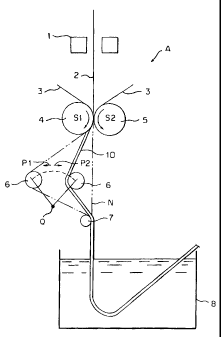
A manufacturing apparatus A for a laminate sheet is shown in
io FIG. 1. An oven is denoted by reference number 1 in which metal sheet 2
passes and is heated continuously, and a couple of laminate rolls 4 and 5 are
shown arranged below oven 1 to press and adhere film 3 to metal sheet 2
coming out the oven 1. At a short distance below the laminate rolls 4 and 5
is arranged a deflector roll 6 rotably and movably in a direction as shown by
arrows PI and P2. Further below deflector roll 6 is arranged a rotatable
guide roll 7. The rotation axes of laminate rolls 4 and 5, deflector roll 6
and
guiding roll 7 are parallel to each other. Quenching tank 8 containing a
quenching liquid is arranged below guide roll 7.
Manufacturing apparatus A' is the one provided with hold down
2o roll 9 for pressing laminate sheet 10 against laminate roll 4 additionally
to
manufacturing apparatus A. Pressure rol19 is rotatable and arranged parallel
to laminate ro114.
The oven 1, for example, can include a dielectric heating oven.
Another heating device such as a heating roll or an induction heating coil
can also be used instead of oven 1. A couple of laminate rolls 4 and 5 are
prior known act as nip rolls for pinching and pressing metal sheet 2 and film
3 running through between them. Normally, laminate rolls 4 and 5 are each
CA 02207272 2006-09-22
-7-
synchronously rotated in opposite directions (arrow S1 and S2) so as to
move the laminate sheet 10 downwardly. The distance between both
laminate rolls is adjustable and rotation speed can also be controlled.
Deflector roll 6 has its both ends rotatably supported by bearings
(not shown), and the bearings are each synchronously movable in the
directions of arrows P 1 and P2 using a control cylinder or the like. The
positions of the bearings are normally adjusted according to a
predetermined laminating condition, but they may be adjusted during the
laminating operation. The bearings are arranged to move straight and
io reciprocatively in a direction perpendicular to the surface of the laminate
sheet. They can also be arranged to rotate about an axis Q which is
positioned below (or above) their axes and parallel to them, that is, the
bearings may be circularly movable as shown by the imaginary line.
Guide roll 7 has its both ends supported by bearings (not shown),
and the bearings are each fixed to a frame or the like. Guide roll 7 is
arranged at such a position as to contact a tangential line N of laminate
rolls
4 and 5. Not shown is an additional drive or nip roll to drive the laminate
sheet 10 into and out from quenching tank 8. Therefore, there causes
tension on laminate sheet 10, and thus a proper tension works on laminate
sheet 10 located between laminate rolls 4 and 5 and guide roll 7.
The manufacturing apparatus constructed as mentioned above is
used as follows. At first, two films 3 and 3a taken out from a supplying
device which is not shown are made to contact both sides of the metal sheet
that has passed through oven 1, and then the three members are passed
through between laminated rolls 4 and 5. Subsequently, the thus laminate
sheet 10 is passed on the left side of deflector ro116 which is deviated to
the
left side from tangential line N shown in FIG. 1, and then it is passed on the
right side of guide roll 7, to thereby take the travelling direction back to
the
CA 02207272 2006-09-22
-8-
original travelling direction. The deviation distance of the deflector roll is
suitably adjusted according to forming conditions and so on. Further, the
laminate sheet 10 is guided downward into quenching tank 8.
As mentioned above, since the laminate sheet 10 coming out
from laminate rolls 4 and 5 travels in a zigzag line, the laminate sheet 10
winds around one laminate roll 4 by a predetermined winding angle
(contacting angle) 6. Contacting angle 0 becomes larger when deflector
roll 6 is deviated to the left side as illustrated in FIG. 1, while it becomes
smaller when deflector roll 6 is deviated to the right side. When the
lo deviation becomes "0", the laminate sheet is guided downward straight as is
conventional, and winding angle becomes 0.
Thus, a pressing force due to the tension of laminate sheet 10 is
worked between film 3 and metal sheet 2 by making laminate sheet 10
contact with one laminate roll 4 by a predetermined winding angle to
thereby increase the period for cooling the laminate sheet. Further in the
case where the pressure roll 9 shown in FIG. 6 is provided, a greater
pressing force can be provided therefore increasing further the contact
between the roll 4 and the laminate sheet 10, which can additionally
improve the cooling effect due to better thermal conduction.
Since the increase of the cooling period is due to the increase of
the applied pressing force worked between film 3 and metal sheet 2, it
affects not only film 3 which contacts one laminate roll 4 but also film 3a
contacting the other side of metal sheet 2 shown by the imaginary line in
FIG. 2. The greater the pressing force and the longer the period for
contacting the laminate roll, the more the total mass of thermal conduction
increases. Therefore, an initial temperature of metal sheet 2 can be raised
due to the increase of the cooling period, and thickness W of melted layer
11 on the side contacting metal sheet 2 can be increased. The relationship
CA 02207272 2006-09-22
-9-
between the contacting period "t" of film 3 to laminate roll 4 and thickness
W of melted layer 11 is substantially in direct proportion as shown in
FIG. 3a.
As the melted layer 11 thickness increases, adhesion of film 3 to
metal sheet 2 during forming increases after being cooled. The relationship
between them is also substantially in direct proportion as shown in FIG. 3b.
In addition to the increase of the melted layer thickness, the increase of the
period during which film 3 is pressed to metal sheet 2 multiplicably affects
film 3 and its adhesion is more improved.
In the above-mentioned example, the increase of adhesion of film
during forming is explained on condition that the laminating speed is the
same as that applied in the conventional method. Conversely speaking, if
the adhesion obtained by the conventional manufacturing method is deemed
sufficient, the laminating can be carried out at a higher speed than is
conventional. Furthermore, winding the film round the laminate roll makes
the contacting period of laminate sheet 10 to laminate roll 4 longer
immediately after the lamination, and the cooling effect by the laminate roll
can be fully obtained. Therefore, film 3 does not wholly melt even when
metal sheet 2 coming out from the oven is heated to a higher temperature,
2o and the unmelted layer can reliably remain outside. Accordingly, even when
the laminating is carried out at a high speed, melted layer 11 having
sufficient thickness can be obtained, thus increasing the film adhesion
during forming. In this case, the orientation of the film in the unmelted
layer is reduced. Between melted layer 11 and slightly oriented layer 12, the
layer whose orientation gradually decreases is intervened.
Next, concrete examples and comparison examples are given and
the effect of the manufacturing method of the present invention is
explained.
CA 02207272 2006-09-22
-10-
(Examples 1 to 3)
A biaxially oriented polyester thermoplastic resin film having a
thickness of 25 m was heat laminated on one side of a strip of
electrolytically chromated steel (TFS) having a thickness of 0.2 mm used
s for can stock using the manufacturing apparatus as shown in FIG. 1. The
temperature of the steel strip just before coming into a couple of laminate
rolls was about 225 C., and that of the laminate roll spontaneously cooled
was about 150 C. The travelling speeds of the laminate sheet were 100,
200 and 400 m/min in
CA 02207272 2006-10-19
-il-
Example 1, 2 and 3, respectively. Winding angle for the laminate
sheet round the laminate roll was 20 in all the exa,mples.
When the laminates thus obtained were formed into a cup
having a diameter of 65 mm and a height of 100 mm using a drawability
taster, no film crack was caused in all the examples and 4.0 to 5.6
N/10 mm of stripping force of the film (adhering strength during
forming) was required to strip the film in each example. The
original ora.entata.on of the film measured by birefringence rate was
about 0.09, while in the laimated film, the melted layer had the
r== '
biretringence rate of 0.01 and the thickness of about 5 to 15 u n1,
slightly oriented layer had the birefringence rate of about 0.058
and the thickness of about 10 to 20 u m, and the intervening layer
had the birefringence rate of 0.01 to 0.05 and the thickness of
about 3 /.t m _
(Comparative examples 1 to 3)
The laminating operation for Comparative examples 1, 2
and 3 were performed on the same conditions (the traveling speed of
the laminate sheet were 100; 200 and 400 mlmin, respectively) as in
Examples exept that the laminate sheet was riot made to wind round
the lami=nate zoll but traveled downward straight. When the
laminate sheet of Comparative example 3 was formed into a cup
substantially the same as Example, film crack was partially caused.
In case of compaxative examples 2 and 3, no film crack was caused,
but stripping force of the film (adhering stzength during forming)
were 4.0 and 2.9 N/10 mm, respectively. The melted layer had the
CA 02207272 2006-10-19
-12-
birefringence rate of 0.01 and the thickness of about 0 to 5{.t m,
the slightly arientIed layer had the birefringence rate of about
0.058 and the thickness of about 20 to 25 kt m, and the intervening
J.ayer had the birefringence rate of 0.01 to 0.05 and the thickness
of about 39 m. The results are shown in Tables 1 and 2.
'-
, ~ .
CA 02207272 2006-10-19
. '
..
. .
=
. .
Table 1
Exaimpie
No traveling thickness of thiokness of adher=ing
speed melted layer oriented layer strength
1 100 m/min 15 11 m 10 m 5.6 N/Id mm
2 200 rn/miri .9 4 m 16 bL m 4.8 N/10 nim
400 m/min 5'.1. m 20 ~G m 4.4 N/.10 mm
' . .
CA 02207272 2006-10-19
. =
=
14-
i
= .
I, .
Tahle 2
Cotpparative eXample
No traveling thickness of thiakness of adhering
speed melted layer oriented layer strength
1 100 m/min 5 g m 20 At m 4. 0 N110 mm
=
2 200 mlmi.n 2.5 g in 22.5 u rn 2.9 N/10 =n
=
3 400 mlmin 0~t m 25 u m 0.5 N/10 mm
. = ,
. .
-
CA 02207272 2006-10-19
-15-
From the results shown above, it is apparent that
according to the manufacturing method of the present invention, a
laminate sheet having excellent adhering strength of the film to a
matallic sheet and hardly to be peeled off during forming can be
obtained, even when the laminate sheet is manufactured at a high
speed of 100 - 400m/min.
Industrial utility
As mentioned above, according to the manufacturing
method of the present invention, the adhering strength of the film
to a mata7,],ic sheet can be improved and it is not reduced even when
the laminating oparation is performed at a high speed. According to
the manufacturing apparatus of the present invention, the
abQve-mentioned manufacturing method can easily be carried out.
_
Summary
A method of producing a laminate sheet (10) comprises the
steps of heating a continuous belt-like metal sheet (2) by a heating
furnace (1), laminating a thermoplastic resin film (3) on at least
one of the surfaces-of the metal sheet, pressing and passing both of
them between a pair of laminate rolls (4 and 5), and thexmally
bonding the film (3) to the metal sheet (2), wherein the laminate
sheet (10) coming out from'between the pair of laminate rolls (4 and
5) is pushed by a deflector roll (6) in a transverse directzon so as
to bias the traveling direction towards the laminate roll (4) which
CA 02207272 2006-10-19
16
contacts the film (3). The invention also discloses an appaxatus
. ~,.
(A) used for this method.
,..