Language selection

Search

Patent 2207349 Summary

Third-party information liability

Some of the information on this Web page has been provided by external sources. The Government of Canada is not responsible for the accuracy, reliability or currency of the information supplied by external sources. Users wishing to rely upon this information should consult directly with the source of the information. Content provided by external sources is not subject to official languages, privacy and accessibility requirements.

Claims and Abstract availability

Any discrepancies in the text and image of the Claims and Abstract are due to differing posting times. Text of the Claims and Abstract are posted:

  • At the time the application is open to public inspection;
  • At the time of issue of the patent (grant).
(12) Patent Application: (11) CA 2207349
(54) English Title: FRAMEWORK FACILITATING POSITIONING OF A TOOL CHEST
(54) French Title: BATI CONCU POUR FACILITER LE POSITIONNEMENT D'UNE TROUSSE A OUTILS
Status: Deemed Abandoned and Beyond the Period of Reinstatement - Pending Response to Notice of Disregarded Communication
Bibliographic Data
(51) International Patent Classification (IPC):
  • B25H 03/02 (2006.01)
  • B25H 03/00 (2006.01)
  • B66C 01/62 (2006.01)
(72) Inventors :
  • CROWSON, KELLY L. (United States of America)
(73) Owners :
  • KELLY L. CROWSON
(71) Applicants :
  • KELLY L. CROWSON (United States of America)
(74) Agent: SMART & BIGGAR LP
(74) Associate agent:
(45) Issued:
(22) Filed Date: 1997-06-09
(41) Open to Public Inspection: 1998-12-09
Availability of licence: N/A
Dedicated to the Public: N/A
(25) Language of filing: English

Patent Cooperation Treaty (PCT): No

(30) Application Priority Data: None

Abstracts

English Abstract


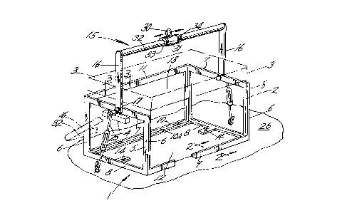
A framework having end members joined by longitudinal members to
define an area for the reception of a tool chest. A bail assembly of
the framework includes a cross member on which an eye equipped sleeve
is positionable and lockable to permit lifting of the tool chest and
framework in the horizontal regardless of being in an unbalanced state.
Fittings on the end members receive turnbuckles for securing the framework
and tool chest to a supporting surface such as the bed of a truck.
Tool chest removal from the framework is prevented by a component of
each end member overlying a tool chest handle.


French Abstract

Bâti comportant des éléments d'extrémité reliés par des éléments longitudinaux pour délimiter la zone de réception d'une trousse à outils. Un ensemble faisant partie de ce bâti est constitué d'une traverse sur laquelle un manchon équipé d'un anneau peut être placé et verrouillé de manière à permettre que l'on soulève la trousse à outils et le bâti à l'horizontale même si elle est en déséquilibre. Des tendeurs, en agissant sur les raccords situés sur les éléments d'extrémité, assurent la fixation du bâti et de la trousse à outils à la surface de soutien qui est, par exemple, la plate-forme d'un camion. Pour empêcher le retrait de la trousse à outils, un composant de chaque élément d'extrémité recouvre une poignée de la trousse.

Claims

Note: Claims are shown in the official language in which they were submitted.


The embodiments of the invention in which an exclusive property or
privilege is claimed are defined as follows:
-1-
A framework for placement about a handle equipped tool chest to
facilitate positioning of the tool chest on a surface, said framework
comprising,
end members of rectangular configuration, longitudinal members
joining said end members, said members defining an open area for the
reception of the tool chest, said end members having fittings for the
reception of turnbuckles for framework tie down to the surface,
a bail assembly including arms and a bar interconnecting the arms,
a sleeve postionable along said bar and including an eye for reception
of a lifting instrumentality, means limiting sleeve movement along said
bar, and
pivot means attaching said arms to said end members.
-2-
The framework claimed in claim 1 wherein said end members each include
a horizontal component for disposition above a tool chest handle to prevent
upward displacement of the tool chest relative the framework.
-3-
In combination,
a tool chest including handles,
a framework comprising end members of rectangular configuration,
longitudinal members joining said end members, said members defining an
open area for the reception of the tool chest,

a bail assembly including arms and a bar interconnecting the arms,
a sleeve positonable along said bar and including an eye for reception
of a lifting instrumentality, means confining the sleeve along said bar,
and
pivot means attaching said arms to said end members.
-4-
The combination claimed in claim 3 wherein said end members include
fittings for the reception of tie down devices.
-5-
The combination claimed in claim 3 wherein said end members of
the framework each include a horizontal component for disposition
respectively immediately above one of the tool chest handles to prevent
upward displacement of the tool chest relative the framework.

Description

Note: Descriptions are shown in the official language in which they were submitted.


~ ' CA 02207349 1997-08-18
FRAMEWORK FACILITATING POSITIONING OF A TOOL CHEST
The present invention concerns generally large tool chests of the
type used by professional mechanics.
In use are large tool chests which when provided with a full compli-
ment of tools may weight two hundred pounds or more. When a mechanic's
job entails the making of repairs at a remote job site, as for example,
in the repair of farm equipment and large trucks, the mechanic must load
his tool chest into a vehicle for travel to the job site. As tool chests,
even the larger ones, provide no lift or attachment points for a cable
the tool chest must be loaded into the vehicle by several men or perhaps
a lift truck and at the end of the trip the operation reversed to return
the tool chest to the mechanic's work station. In addition to the time
and effort expended in accomplishing this task, there is a degree of risk
to the workers and damage to the tool chest.
A complication in the lifting of a heavy tool chest is that the chest
should be lifted in the horizontal to prevent shifting of tools and parts
in the chest to avoid having to reorganize the tool chest after each
repositioning or lifting.
A further problem encountered is that tool chests have hingedly
mounted lids and a series of drawers, the opening and closing of which
must not be impeded during the job at hand. Further, the overall size of
the tool chest should not be increased.

' CA 02207349 1997-08-18
In the prior art are devices for attachment to a load with provision
for positioning an eye for reception of a lifting cable to prevent tilting
of a load. Examples of such devices are disclosed in U. S. Patents
1,148,679; 3,549,190; 3,596,969 and 4,597,602, none of which are believed
suitable for use with a tool chest.
U. S. Patent 5,181,756 shows a framework for the lifting of building
materials with a V-shaped hoisting bar. U. S. Patent 1,148,679 shows an
attachment for a tool with a positionable sleeve on a lift bail to ensure
lifting of the tool in the horizontal.
The present invention is embodied in a framework for reception of a
tool chest to facilitate lifting of same into and out of the cargo areas
of repair vehicles.
The framework includes welded frame members which form a partial
enclosure into which a tool chest is positioned and in which it may remain
for transport and when at the mechanic's work station in a shop. A frame-
work bail is swingably mounted to enable storing of the bail in an incon-
spicuous manner rearward of the framewrok. A lift point of the bail
assembly is adjustably mounted for positioning and locking the bail to
ensure the chest remains at or near the horizontal during loading and
unloading from a transport vehicle. The tool chest is confined in the
framework by a framewrok member being located immediately above a handle
of the tool chest. Further, the framework may include tie down appendages
for convenient installation of locks which also cooperate with fittings
in place on the transport vehicle.

' CA 02207349 1997-08-18
Important objectives of the present invention include the provision
of a framework in which a tool chest may be more or less permanently
installed to facilitate lifting of the chest into and out of repair vehicles
for transport to a remote or emergency job site; the provision of a frame-
work for a large tool chest to facilitate positioning the chest which
does not add appreciably to the bulky nature of such tool chests to enable
the tool chest to be left permanently in place in the frameworkj the pro-
vision of a framework which includes a bail on which is adjustably carried
an eye for reception of a hook equipped cable or the like with the eye
positionable to ensure lifting of the chest in a substantially horizontal
condition.
In the drawings:
Figure 1 is a perspective view of the present framework with a tool
chest therein shown in phantom linesi
Figure 2 is a vertical sectional view taken along line 2-2 of Figure 1;
Figure 3 is a horizontal view of bail attachment structure and taken
along line 3-3 of Figure 1.
With attention to the drawings wherein applied reference numerals
indicate parts similarly hereinafter identified, the reference numeral 1
indicates generally the present framework of welded construction.
A tool chest is shown in phantom lines at 2 and includes a lid 3. A
tool chest handle is at 4.
The framework includes upright end members 5 of rectangular shape each
with a pair of vertical components 6 and a top component 7 of channel section.
A lower component 8 of each end member is of tubular stock.

~ CA 02207349 1997-08-18
Longitudinal lower members of the framework are at 9 and 10. A
shoulder at 9A and 10A on each of the members contributes to confining
the tool chest against displacement during transport. A top longitudinal
member is at 11. Accordingly, a frontal open area of the framework is
provided at 12 while an upper open area at 13 is defined by the frame-
work. The end members are in close proximity with the side walls of the
tool chest. Framework extensions at 14 ensure a suitable lifting area
surface of the framework.
A bail assembly is generally at 15 and includes arms 16 attached to
the top components 7 of the framework by pivot means 17. Said pivot means
includes a pintle 20 having a head 21 with the pintle extending through
the end member to receive a nut 22 which is welded to the top component.
A lower end of arm 16 is apertured to receive the pintle. Washers are at
18 and 19 with the latter tacked to the end member by welds 23. The pintle
head 21 receives a ring at 24 with which a turnbuckle attached hook 25 may
be engaged to secure the framework and tool chest therein against slippage
on a supporting surface 26 which may be the bed of a truck.
An eye at 30 is carried by a sleeve 31 in place on a cross member 32
of the bail assembly. Locks at 33 and 34 confine sleeve 31 at a desired
point therealong near or at the center of gravity of the tool chest and
framework to ensure the chest remaining horizontal during lifting by the
hook equipped cable of a hoist (not shown). The locks 33 and 34 may be
embodied in rings each having a set screw for contact with cross member 32.

- ' CA 02207349 1997-08-18
Sleeve 31 may be positioned after partial lifting of the chest and
framework indicates an adjustment is desired.
In use, the tool chest is positioned in the framework subsequent to
removal of tool chest handles as at 4. Upon handle reattachment, the tool
chest is prevented from upward displac~ment, relative the framework, as
the handles are restricted by upper components 7 of the framework. Forward
and rearward displacement of the tool chest is prevented by shoulders 9A
and lOA of the lower longitudinal members of the framework. As large tool
chests most often include locking means preventing access to the tool chest
interior, removing of handles 7 by an unauthorized person is not possible.
Theft of the combined tool chest and framework from a truck bed is not
feasible by reason of weight which necessitates the use of a crane of the
type commonly found in machine shops. Both during transport of the frame-
work housed tool chest or at a mechanic's work station in a shop, bail
assembly 15 is swung downward and to the rear of the framework so as to
not hinder access to the tool chest interior. If desired, sheet material
may be applied to the end members and to overlie longitudinal members 10
and 11 to prevent damage to the tool chest when carried in a truck bed
with other equipment or supplies.
While I have shown but one embodiment of the invention, it will be
apparent to those skilled in the art that the invention may be embodied
still otherwise without departing from the spirit and scope of the inven-
tion.

Representative Drawing
A single figure which represents the drawing illustrating the invention.
Administrative Status

2024-08-01:As part of the Next Generation Patents (NGP) transition, the Canadian Patents Database (CPD) now contains a more detailed Event History, which replicates the Event Log of our new back-office solution.

Please note that "Inactive:" events refers to events no longer in use in our new back-office solution.

For a clearer understanding of the status of the application/patent presented on this page, the site Disclaimer , as well as the definitions for Patent , Event History , Maintenance Fee  and Payment History  should be consulted.

Event History

Description Date
Inactive: IPC from MCD 2006-03-12
Application Not Reinstated by Deadline 2003-06-09
Time Limit for Reversal Expired 2003-06-09
Deemed Abandoned - Failure to Respond to Maintenance Fee Notice 2002-06-10
Inactive: Abandon-RFE+Late fee unpaid-Correspondence sent 2002-06-10
Application Published (Open to Public Inspection) 1998-12-09
Inactive: Correspondence - Transfer 1998-06-19
Classification Modified 1997-09-03
Inactive: First IPC assigned 1997-09-03
Inactive: IPC assigned 1997-09-03
Inactive: Filing certificate - No RFE (English) 1997-08-15
Filing Requirements Determined Compliant 1997-08-15
Application Received - Regular National 1997-08-15

Abandonment History

Abandonment Date Reason Reinstatement Date
2002-06-10

Maintenance Fee

The last payment was received on 2001-05-22

Note : If the full payment has not been received on or before the date indicated, a further fee may be required which may be one of the following

  • the reinstatement fee;
  • the late payment fee; or
  • additional fee to reverse deemed expiry.

Patent fees are adjusted on the 1st of January every year. The amounts above are the current amounts if received by December 31 of the current year.
Please refer to the CIPO Patent Fees web page to see all current fee amounts.

Fee History

Fee Type Anniversary Year Due Date Paid Date
Application fee - small 1997-06-09
MF (application, 2nd anniv.) - small 02 1999-06-09 1999-04-23
MF (application, 3rd anniv.) - small 03 2000-06-09 2000-04-14
MF (application, 4th anniv.) - small 04 2001-06-11 2001-05-22
Owners on Record

Note: Records showing the ownership history in alphabetical order.

Current Owners on Record
KELLY L. CROWSON
Past Owners on Record
None
Past Owners that do not appear in the "Owners on Record" listing will appear in other documentation within the application.
Documents

To view selected files, please enter reCAPTCHA code :


To view images, click a link in the Document Description column. To download the documents, select one or more checkboxes in the first column and then click the "Download Selected in PDF format (Zip Archive)" or the "Download Selected as Single PDF" button.

List of published and non-published patent-specific documents on the CPD .

If you have any difficulty accessing content, you can call the Client Service Centre at 1-866-997-1936 or send them an e-mail at CIPO Client Service Centre.


Document
Description 
Date
(yyyy-mm-dd) 
Number of pages   Size of Image (KB) 
Representative drawing 1998-12-15 1 19
Abstract 1997-06-08 1 17
Description 1997-06-08 5 178
Claims 1997-06-08 2 46
Drawings 1997-06-08 1 39
Filing Certificate (English) 1997-08-14 1 165
Request for evidence or missing transfer 1998-06-09 1 112
Reminder of maintenance fee due 1999-02-09 1 110
Reminder - Request for Examination 2002-02-11 1 117
Courtesy - Abandonment Letter (Request for Examination) 2002-08-04 1 171
Courtesy - Abandonment Letter (Maintenance Fee) 2002-07-07 1 183
Correspondence 2000-04-13 1 30
Correspondence 2001-05-21 1 34