Sélection de la langue

Search

Sommaire du brevet 2207349 

Énoncé de désistement de responsabilité concernant l'information provenant de tiers

Une partie des informations de ce site Web a été fournie par des sources externes. Le gouvernement du Canada n'assume aucune responsabilité concernant la précision, l'actualité ou la fiabilité des informations fournies par les sources externes. Les utilisateurs qui désirent employer cette information devraient consulter directement la source des informations. Le contenu fourni par les sources externes n'est pas assujetti aux exigences sur les langues officielles, la protection des renseignements personnels et l'accessibilité.

Disponibilité de l'Abrégé et des Revendications

L'apparition de différences dans le texte et l'image des Revendications et de l'Abrégé dépend du moment auquel le document est publié. Les textes des Revendications et de l'Abrégé sont affichés :

  • lorsque la demande peut être examinée par le public;
  • lorsque le brevet est émis (délivrance).
(12) Demande de brevet: (11) CA 2207349
(54) Titre français: BATI CONCU POUR FACILITER LE POSITIONNEMENT D'UNE TROUSSE A OUTILS
(54) Titre anglais: FRAMEWORK FACILITATING POSITIONING OF A TOOL CHEST
Statut: Réputée abandonnée et au-delà du délai pour le rétablissement - en attente de la réponse à l’avis de communication rejetée
Données bibliographiques
Abrégés

Abrégé français

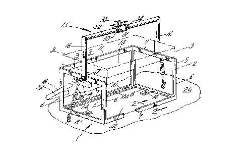
Bâti comportant des éléments d'extrémité reliés par des éléments longitudinaux pour délimiter la zone de réception d'une trousse à outils. Un ensemble faisant partie de ce bâti est constitué d'une traverse sur laquelle un manchon équipé d'un anneau peut être placé et verrouillé de manière à permettre que l'on soulève la trousse à outils et le bâti à l'horizontale même si elle est en déséquilibre. Des tendeurs, en agissant sur les raccords situés sur les éléments d'extrémité, assurent la fixation du bâti et de la trousse à outils à la surface de soutien qui est, par exemple, la plate-forme d'un camion. Pour empêcher le retrait de la trousse à outils, un composant de chaque élément d'extrémité recouvre une poignée de la trousse.


Abrégé anglais


A framework having end members joined by longitudinal members to
define an area for the reception of a tool chest. A bail assembly of
the framework includes a cross member on which an eye equipped sleeve
is positionable and lockable to permit lifting of the tool chest and
framework in the horizontal regardless of being in an unbalanced state.
Fittings on the end members receive turnbuckles for securing the framework
and tool chest to a supporting surface such as the bed of a truck.
Tool chest removal from the framework is prevented by a component of
each end member overlying a tool chest handle.

Revendications

Note : Les revendications sont présentées dans la langue officielle dans laquelle elles ont été soumises.


The embodiments of the invention in which an exclusive property or
privilege is claimed are defined as follows:
-1-
A framework for placement about a handle equipped tool chest to
facilitate positioning of the tool chest on a surface, said framework
comprising,
end members of rectangular configuration, longitudinal members
joining said end members, said members defining an open area for the
reception of the tool chest, said end members having fittings for the
reception of turnbuckles for framework tie down to the surface,
a bail assembly including arms and a bar interconnecting the arms,
a sleeve postionable along said bar and including an eye for reception
of a lifting instrumentality, means limiting sleeve movement along said
bar, and
pivot means attaching said arms to said end members.
-2-
The framework claimed in claim 1 wherein said end members each include
a horizontal component for disposition above a tool chest handle to prevent
upward displacement of the tool chest relative the framework.
-3-
In combination,
a tool chest including handles,
a framework comprising end members of rectangular configuration,
longitudinal members joining said end members, said members defining an
open area for the reception of the tool chest,

a bail assembly including arms and a bar interconnecting the arms,
a sleeve positonable along said bar and including an eye for reception
of a lifting instrumentality, means confining the sleeve along said bar,
and
pivot means attaching said arms to said end members.
-4-
The combination claimed in claim 3 wherein said end members include
fittings for the reception of tie down devices.
-5-
The combination claimed in claim 3 wherein said end members of
the framework each include a horizontal component for disposition
respectively immediately above one of the tool chest handles to prevent
upward displacement of the tool chest relative the framework.

Description

Note : Les descriptions sont présentées dans la langue officielle dans laquelle elles ont été soumises.


~ ' CA 02207349 1997-08-18
FRAMEWORK FACILITATING POSITIONING OF A TOOL CHEST
The present invention concerns generally large tool chests of the
type used by professional mechanics.
In use are large tool chests which when provided with a full compli-
ment of tools may weight two hundred pounds or more. When a mechanic's
job entails the making of repairs at a remote job site, as for example,
in the repair of farm equipment and large trucks, the mechanic must load
his tool chest into a vehicle for travel to the job site. As tool chests,
even the larger ones, provide no lift or attachment points for a cable
the tool chest must be loaded into the vehicle by several men or perhaps
a lift truck and at the end of the trip the operation reversed to return
the tool chest to the mechanic's work station. In addition to the time
and effort expended in accomplishing this task, there is a degree of risk
to the workers and damage to the tool chest.
A complication in the lifting of a heavy tool chest is that the chest
should be lifted in the horizontal to prevent shifting of tools and parts
in the chest to avoid having to reorganize the tool chest after each
repositioning or lifting.
A further problem encountered is that tool chests have hingedly
mounted lids and a series of drawers, the opening and closing of which
must not be impeded during the job at hand. Further, the overall size of
the tool chest should not be increased.

' CA 02207349 1997-08-18
In the prior art are devices for attachment to a load with provision
for positioning an eye for reception of a lifting cable to prevent tilting
of a load. Examples of such devices are disclosed in U. S. Patents
1,148,679; 3,549,190; 3,596,969 and 4,597,602, none of which are believed
suitable for use with a tool chest.
U. S. Patent 5,181,756 shows a framework for the lifting of building
materials with a V-shaped hoisting bar. U. S. Patent 1,148,679 shows an
attachment for a tool with a positionable sleeve on a lift bail to ensure
lifting of the tool in the horizontal.
The present invention is embodied in a framework for reception of a
tool chest to facilitate lifting of same into and out of the cargo areas
of repair vehicles.
The framework includes welded frame members which form a partial
enclosure into which a tool chest is positioned and in which it may remain
for transport and when at the mechanic's work station in a shop. A frame-
work bail is swingably mounted to enable storing of the bail in an incon-
spicuous manner rearward of the framewrok. A lift point of the bail
assembly is adjustably mounted for positioning and locking the bail to
ensure the chest remains at or near the horizontal during loading and
unloading from a transport vehicle. The tool chest is confined in the
framework by a framewrok member being located immediately above a handle
of the tool chest. Further, the framework may include tie down appendages
for convenient installation of locks which also cooperate with fittings
in place on the transport vehicle.

' CA 02207349 1997-08-18
Important objectives of the present invention include the provision
of a framework in which a tool chest may be more or less permanently
installed to facilitate lifting of the chest into and out of repair vehicles
for transport to a remote or emergency job site; the provision of a frame-
work for a large tool chest to facilitate positioning the chest which
does not add appreciably to the bulky nature of such tool chests to enable
the tool chest to be left permanently in place in the frameworkj the pro-
vision of a framework which includes a bail on which is adjustably carried
an eye for reception of a hook equipped cable or the like with the eye
positionable to ensure lifting of the chest in a substantially horizontal
condition.
In the drawings:
Figure 1 is a perspective view of the present framework with a tool
chest therein shown in phantom linesi
Figure 2 is a vertical sectional view taken along line 2-2 of Figure 1;
Figure 3 is a horizontal view of bail attachment structure and taken
along line 3-3 of Figure 1.
With attention to the drawings wherein applied reference numerals
indicate parts similarly hereinafter identified, the reference numeral 1
indicates generally the present framework of welded construction.
A tool chest is shown in phantom lines at 2 and includes a lid 3. A
tool chest handle is at 4.
The framework includes upright end members 5 of rectangular shape each
with a pair of vertical components 6 and a top component 7 of channel section.
A lower component 8 of each end member is of tubular stock.

~ CA 02207349 1997-08-18
Longitudinal lower members of the framework are at 9 and 10. A
shoulder at 9A and 10A on each of the members contributes to confining
the tool chest against displacement during transport. A top longitudinal
member is at 11. Accordingly, a frontal open area of the framework is
provided at 12 while an upper open area at 13 is defined by the frame-
work. The end members are in close proximity with the side walls of the
tool chest. Framework extensions at 14 ensure a suitable lifting area
surface of the framework.
A bail assembly is generally at 15 and includes arms 16 attached to
the top components 7 of the framework by pivot means 17. Said pivot means
includes a pintle 20 having a head 21 with the pintle extending through
the end member to receive a nut 22 which is welded to the top component.
A lower end of arm 16 is apertured to receive the pintle. Washers are at
18 and 19 with the latter tacked to the end member by welds 23. The pintle
head 21 receives a ring at 24 with which a turnbuckle attached hook 25 may
be engaged to secure the framework and tool chest therein against slippage
on a supporting surface 26 which may be the bed of a truck.
An eye at 30 is carried by a sleeve 31 in place on a cross member 32
of the bail assembly. Locks at 33 and 34 confine sleeve 31 at a desired
point therealong near or at the center of gravity of the tool chest and
framework to ensure the chest remaining horizontal during lifting by the
hook equipped cable of a hoist (not shown). The locks 33 and 34 may be
embodied in rings each having a set screw for contact with cross member 32.

- ' CA 02207349 1997-08-18
Sleeve 31 may be positioned after partial lifting of the chest and
framework indicates an adjustment is desired.
In use, the tool chest is positioned in the framework subsequent to
removal of tool chest handles as at 4. Upon handle reattachment, the tool
chest is prevented from upward displac~ment, relative the framework, as
the handles are restricted by upper components 7 of the framework. Forward
and rearward displacement of the tool chest is prevented by shoulders 9A
and lOA of the lower longitudinal members of the framework. As large tool
chests most often include locking means preventing access to the tool chest
interior, removing of handles 7 by an unauthorized person is not possible.
Theft of the combined tool chest and framework from a truck bed is not
feasible by reason of weight which necessitates the use of a crane of the
type commonly found in machine shops. Both during transport of the frame-
work housed tool chest or at a mechanic's work station in a shop, bail
assembly 15 is swung downward and to the rear of the framework so as to
not hinder access to the tool chest interior. If desired, sheet material
may be applied to the end members and to overlie longitudinal members 10
and 11 to prevent damage to the tool chest when carried in a truck bed
with other equipment or supplies.
While I have shown but one embodiment of the invention, it will be
apparent to those skilled in the art that the invention may be embodied
still otherwise without departing from the spirit and scope of the inven-
tion.

Dessin représentatif
Une figure unique qui représente un dessin illustrant l'invention.
États administratifs

2024-08-01 : Dans le cadre de la transition vers les Brevets de nouvelle génération (BNG), la base de données sur les brevets canadiens (BDBC) contient désormais un Historique d'événement plus détaillé, qui reproduit le Journal des événements de notre nouvelle solution interne.

Veuillez noter que les événements débutant par « Inactive : » se réfèrent à des événements qui ne sont plus utilisés dans notre nouvelle solution interne.

Pour une meilleure compréhension de l'état de la demande ou brevet qui figure sur cette page, la rubrique Mise en garde , et les descriptions de Brevet , Historique d'événement , Taxes périodiques et Historique des paiements devraient être consultées.

Historique d'événement

Description Date
Inactive : CIB de MCD 2006-03-12
Demande non rétablie avant l'échéance 2003-06-09
Le délai pour l'annulation est expiré 2003-06-09
Réputée abandonnée - omission de répondre à un avis sur les taxes pour le maintien en état 2002-06-10
Inactive : Abandon.-RE+surtaxe impayées-Corr envoyée 2002-06-10
Demande publiée (accessible au public) 1998-12-09
Inactive : Correspondance - Transfert 1998-06-19
Symbole de classement modifié 1997-09-03
Inactive : CIB en 1re position 1997-09-03
Inactive : CIB attribuée 1997-09-03
Inactive : Certificat de dépôt - Sans RE (Anglais) 1997-08-15
Exigences de dépôt - jugé conforme 1997-08-15
Demande reçue - nationale ordinaire 1997-08-15

Historique d'abandonnement

Date d'abandonnement Raison Date de rétablissement
2002-06-10

Taxes périodiques

Le dernier paiement a été reçu le 2001-05-22

Avis : Si le paiement en totalité n'a pas été reçu au plus tard à la date indiquée, une taxe supplémentaire peut être imposée, soit une des taxes suivantes :

  • taxe de rétablissement ;
  • taxe pour paiement en souffrance ; ou
  • taxe additionnelle pour le renversement d'une péremption réputée.

Les taxes sur les brevets sont ajustées au 1er janvier de chaque année. Les montants ci-dessus sont les montants actuels s'ils sont reçus au plus tard le 31 décembre de l'année en cours.
Veuillez vous référer à la page web des taxes sur les brevets de l'OPIC pour voir tous les montants actuels des taxes.

Historique des taxes

Type de taxes Anniversaire Échéance Date payée
Taxe pour le dépôt - petite 1997-06-09
TM (demande, 2e anniv.) - petite 02 1999-06-09 1999-04-23
TM (demande, 3e anniv.) - petite 03 2000-06-09 2000-04-14
TM (demande, 4e anniv.) - petite 04 2001-06-11 2001-05-22
Titulaires au dossier

Les titulaires actuels et antérieures au dossier sont affichés en ordre alphabétique.

Titulaires actuels au dossier
KELLY L. CROWSON
Titulaires antérieures au dossier
S.O.
Les propriétaires antérieurs qui ne figurent pas dans la liste des « Propriétaires au dossier » apparaîtront dans d'autres documents au dossier.
Documents

Pour visionner les fichiers sélectionnés, entrer le code reCAPTCHA :


Pour visualiser une image, cliquer sur un lien dans la colonne description du document. Pour télécharger l'image (les images), cliquer l'une ou plusieurs cases à cocher dans la première colonne et ensuite cliquer sur le bouton "Télécharger sélection en format PDF (archive Zip)" ou le bouton "Télécharger sélection (en un fichier PDF fusionné)".

Liste des documents de brevet publiés et non publiés sur la BDBC .

Si vous avez des difficultés à accéder au contenu, veuillez communiquer avec le Centre de services à la clientèle au 1-866-997-1936, ou envoyer un courriel au Centre de service à la clientèle de l'OPIC.


Description du
Document 
Date
(aaaa-mm-jj) 
Nombre de pages   Taille de l'image (Ko) 
Dessin représentatif 1998-12-15 1 19
Abrégé 1997-06-08 1 17
Description 1997-06-08 5 178
Revendications 1997-06-08 2 46
Dessins 1997-06-08 1 39
Certificat de dépôt (anglais) 1997-08-14 1 165
Demande de preuve ou de transfert manquant 1998-06-09 1 112
Rappel de taxe de maintien due 1999-02-09 1 110
Rappel - requête d'examen 2002-02-11 1 117
Courtoisie - Lettre d'abandon (requête d'examen) 2002-08-04 1 171
Courtoisie - Lettre d'abandon (taxe de maintien en état) 2002-07-07 1 183
Correspondance 2000-04-13 1 30
Correspondance 2001-05-21 1 34