Language selection

Search

Patent 2207755 Summary

Third-party information liability

Some of the information on this Web page has been provided by external sources. The Government of Canada is not responsible for the accuracy, reliability or currency of the information supplied by external sources. Users wishing to rely upon this information should consult directly with the source of the information. Content provided by external sources is not subject to official languages, privacy and accessibility requirements.

Claims and Abstract availability

Any discrepancies in the text and image of the Claims and Abstract are due to differing posting times. Text of the Claims and Abstract are posted:

  • At the time the application is open to public inspection;
  • At the time of issue of the patent (grant).
(12) Patent: (11) CA 2207755
(54) English Title: A DRILLING METHOD AND BIT ASSEMBLY TO REALIZE THE METHOD
(54) French Title: PROCEDE DE FORAGE ET ENSEMBLE TREPAN POUR LA REALISATION DE CE PROCEDE
Status: Term Expired - Post Grant Beyond Limit
Bibliographic Data
(51) International Patent Classification (IPC):
  • E21B 7/20 (2006.01)
  • E21B 10/00 (2006.01)
  • E21B 17/046 (2006.01)
(72) Inventors :
  • ILOMAKI, VALTO (Finland)
(73) Owners :
  • OY ATLAS COPCO ROTEX AB
(71) Applicants :
  • OY ATLAS COPCO ROTEX AB (Finland)
(74) Agent: BERESKIN & PARR LLP/S.E.N.C.R.L.,S.R.L.
(74) Associate agent:
(45) Issued: 2007-05-15
(86) PCT Filing Date: 1995-12-13
(87) Open to Public Inspection: 1996-06-20
Examination requested: 2002-12-13
Availability of licence: N/A
Dedicated to the Public: N/A
(25) Language of filing: English

Patent Cooperation Treaty (PCT): Yes
(86) PCT Filing Number: PCT/FI1995/000678
(87) International Publication Number: FI1995000678
(85) National Entry: 1997-06-13

(30) Application Priority Data:
Application No. Country/Territory Date
945852 (Finland) 1994-12-13

Abstracts

English Abstract


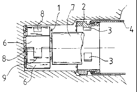
A method to drill a hole in the soil by a bit assembly and a bit assembly
comprising a ring-shaped bit (2) to drill the outer circle of
the hole and to which a protection tube system (4), mounted in the hole while
drilling, is coupled, and a cylindric inner bit (1) to drill the
center portion of the hole, from which bit at least the rotative motion is
transmitted to the outer bit (2). Drilling by the outer bit (2) and
pulling out the protection tube (4) are disconnected upon need by reverse
rotation of the inner bit, whereafter drilling is continued with the
inner bit (1) only.


French Abstract

Cette invention se rapporte à un procédé servant à forer un trou dans le sol à l'aide d'un ensemble trépan, ainsi qu'à un ensemble trépan, qui comprend un trépan de forme annulaire (2) servant à forer la circonférence externe circulaire du trou et auquel est couplé un système de tube de protection (4), monté dans le trou pendant l'opération de forage, ainsi qu'un trépan interne cylindrique (1) qui sert à forer la partie centrale du trou et à partir duquel au moins le mouvement de rotation est transmis au trépan externe. L'opération de forage par le trépan externe (2) et l'opération d'extraction du tube de protection (4) sont séparées lorsque c'est nécessaire, par rotation inverse du trépan interne, puis l'opération de forage est poursuivie à l'aide du trépan interne (1) uniquement.

Claims

Note: Claims are shown in the official language in which they were submitted.


CLAIMS:
1. An inner bit movable through either open end of a ring bit
axially both forward and backward out of the same, whereby the
drill bit drills an outer circumference of a hole and securable
to said ring bit to form a united bit assembly for drilling a
hole or tunnel in soil, said inner bit including transverse
grooves on an outer cylindrical surface with respect to an axial
direction, side faces of the grooves protruding in a direction of
a radius of the inner bit and transmitting impacts and rotation
to the ring bit.
2. An inner bit according to claim 1 further comprising axial
grooves.
3. An inner bit according to claim 1 wherein the transverse
grooves are sequentially arranged on the inner bit, the
transverse grooves being open at one end and closed at an
opposite end by an end face protruding in a direction of a radius
of the inner bit.
4. A method for drilling a hole in soil by means for a bit
assembly comprising a ring-shaped outer drill bit for drilling an
outer circumference of the hole, said outer bit being arranged to
pull a protection tube system into the hole when the drilling
advances, a cylindrical inner bit for drilling a center portion
of the hole and a locking system comprising grooves and
projecting parts, the projecting parts being located on one of a
cylindrical inner surface of the outer bit and a cylindrical
outer surface of the inner bit and the grooves being located in
the other of the cylindrical inner surface of the outer bit and
the cylindrical outer surface of the inner bit, said projections
being movable into said grooves for locking said inner and outer

6
bits and movable out of said grooves to allow transverse movement
between said inner and outer bits, rotative motion of said bit
assembly being transmitted from said inner bit to said outer bit
by means of said locking system, said method comprising the steps
of:
locking said inner and outer bits;
drilling by means of the outer bit and pulling of the
protection tube system;
disconnecting the outer bit from the inner bit at a desired
drilling depth; and
continuing drilling with said inner bit only.
5. A method according to claim 4, wherein, during said step of
drilling by means of said outer bit, the inner bit transmits
impacts to the outer bit by means of said projecting parts.
6. A method according to claim 4, wherein, when said inner bit
and said outer bit are unlocked during said step of
disconnecting, the inner bit is movable through the outer bit in
forward and backward transverse directions and, upon need, the
outer bit is lockable to the inner bit.
7. A method according to claim 4, wherein a first portion of a
hole is drilled during the step of drilling by the locked inner
and outer bits, and a second portion of the hole is drilled by
the inner bit during said step of continuing drilling, said
method further comprising the step of removing the inner bit from
the hole either alone or together with the outer bit and the
protection tube.
8. A bit assembly including:
an inner bit for drilling a center of a hole;

7
an outer bit for drilling an outer circumference of said
hole, the inner bit being threaded through the outer bit;
a protection tube mounted in said hole during drilling and
coupled to said outer bit; and
a rotation-transmitting joint between said inner and outer
bits, the joint including a locking system comprising grooves and
projecting parts, the projecting parts being located on one of a
cylindrical inner surface of the outer bit and a cylindrical
outer surface of the inner bit, and grooves being located in the
other of the cylindrical inner surface of the outer bit and the
cylindrical outer surface of the inner bit, the projecting parts
being movable into said grooves for locking said inner and outer
bits to allow drilling by said outer bit and movable out of said
grooves to allow movement of said inner bit out of said outer bit
to allow drilling by said inner bit only.
9. A bit assembly according to claim 8, wherein the locking
system comprises one or more sequential bayonet joints between
the inner bit and the outer bit for transmitting rotative motion
and drilling force from the inner bit to the outer bit.
10.A bit assembly according to claim 8, wherein one of the
grooves extending in an axial direction in one of the inner and
outer bits comprises a flow channel for flushing medium.
11.The bit assembly according to claim 8, wherein said grooves
are located in the inner bit and the projecting parts are located
in the outer bit.

Description

Note: Descriptions are shown in the official language in which they were submitted.


CA 02207755 2005-05-06
~
A DRILLING METHOD AND BIT ASSEMBLY TO REALIZE THE METHOD
This invention relates to a method for drilling a hole in the
soil and to a bit assembly and a drill bit for use in drilling
a hole or tunnel in the soil.
Previously known are, for instance from patent specifications FI
933074 and GB 2 255 365, double bit assemblies where the inner
bit that drills the centre hole can be pulled out from the hole,
while the ring bit that drills the outer hole circle is left in
the bore. However, in these examples the inner bit can be pulled
out from the hole after drilling and also reinstalled if dril-
ling is continued.
On drilling a hole in the soil, the most general case is that
the first portion of the hole is made in soft soil, whereby a
protection tube is pulled into the drilled hole. Eventually, on
hitting rock, the protection tube is not needed anymore. Dril-
ling can then be continued without a protection tube if change
of the drilling procedure is easy. The problem is the difficulty
to change the way of drilling. The inner bit must then be pulled
out from the hole and replaced by a bit that drills a hole with
a smaller diameter. At this replacement, the complete drilling
equipment is pulled out from the hole and reinstalled furnished
with a new rock-drilling bit. This takes time and money, especi-
ally if the first bore in the soil is long.
In accordance with one aspect of the invention there is
provided a method for drilling a hole in soil by means for a
bit assembly comprising a ring-shaped outer drill bit for
drilling an outer circumference of the hole, said outer bit
being arranged to pull a protection tube system into the hole
when the drilling advances, a cylindrical inner bit for
drilling a center portion of the hole and a locking system
comprising grooves and projecting parts, the projecting parts
being located on one of a cylindrical inner surface of the
outer bit and a cylindrical outer surface of the inner bit and

CA 02207755 2005-05-06
la
the grooves being located in the other of the cylindrical inner
surface of the outer bit and the cylindrical outer surface of
the inner bit, said projections being movable into said grooves
for locking said inner and outer bits and movable out of said
grooves to allow transverse movement between said inner and
outer bits, rotative motion of said bit assembly being
transmitted from said inner bit to said outer bit by means of
said locking system. The method involves the steps of locking
said inner and outer bits, drilling by means of the outer bit
and pulling of the protection tube, disconnecting the outer bit
from the inner bit at a desired drilling depth and continuing
drilling with said inner bit only.
The invention also provides a bit assembly which includes an
inner bit for drilling a center of a hole, an outer bit for
drilling an outer circumference of the hole, the inner bit
being threaded through the outer bit, a protection tube mounted
in the hole during drilling and coupled to the outer bit and a
rotation-transmitting joint between inner and outer bits. The
joint includes a locking system comprising grooves and
projecting parts, the projecting parts being located on one of
a cylindrical inner surface of the outer bit and a cylindrical
outer surface of the inner bit. The grooves are located in the
other of the cylindrical inner surface of the outer bit and the
cylindrical outer surface of the inner bit. The projecting
parts are movable into the grooves for locking the inner and
outer bits to allow drilling by the outer bit and are movable
out of the grooves to allow movement of the inner bit out of
the outer bit to allow drilling by the inner bit only.
The invention also provides an inner bit movable through either
open end of a ring bit that drills an outer circumference of a
hole and securable to said ring bit to form a united bit
assembly for drilling a hole or tunnel in soil, said inner bit
including transverse grooves on an outer cylindrical surface
with respect to an axial direction, side faces of the grooves

CA 02207755 2005-05-06
lb
protruding in a direction of a radius of the inner bit and
transmitting impacts and rotation to the ring bit.
The advantage of this invention is that a hole requiring a
protection tube is drilled with the same bit assembly as a hole
into rock. When the protection tube is not needed,
drilling

CA 02207755 1997-06-13
WO 96/18798 PCT/FI95/00678
2
proceeds nonstop with the inner bit only. In case drilling is
stopped in a dead end, the inner bit can be pulled out through
the outer bit. Even the outer bit can be pulled out from the
bore on condition that also the protection tube is pulled out
simultaneously.
The bit assembly and the method can be applied to drilling by
hammering but also to bits rotating only. The groove in the
bayonet joint that opens in both of the axial directions is
favourably arranged as a flow channel for flushing medium,
whereat the joint is a simple construction.
In the following the invention is disclosed with reference to
the enclosed drawing, where
Fig. 1 shows a section of the bit assembly along line A-A.
Fig. 2 shows the bit assembly viewed from the front.
Fig. 3 shows the inner bit surface viewed from one side.
Fig. 4 shows a section of bore, where drilling proceeds by the
inner bit only.
Fig. 5 shows a cross-section of the ring bit.
Figure 1 illustrates a section of the bit assembly including a
cylindric inner bit 1 fastened to the head of hammer 7, a ring-
shaped outer bit 2 around the inner bit and a protection tube 4
mounted in the hole while drilling and reaching the outer shell
of outer bit 2. The inner bit 1 and outer bit 2 are intercon-
nected by a bayonet joint, where rotation is transmitted to the
outer bit by the inner bit. The inner bit 1 also transmits the
hammer impacts to outer bit 2. Outer bit 2 pulls protection tube
4 into the hole by means of the joint lap between them, which
has restriction for the mutual axial motion.
Figure 2 shows that in the circle between bits 1 and 2 three
bayonet joints are placed, where in the inner bit 1 three axial
grooves 6 are formed to run through the bit. Correspondingly,
there are in inner bit 2 three projecting parts with the same
spacing and moving in grooves 6. Sidewards from grooves 6 in bit

CA 02207755 1997-06-13
WO 96/18798 PCT/FI95/00678
3
1 surface, as per figure 3, there are notches for projecting
parts 3, into which the projecting parts are guided due to the
mutual rotation of the bits. Thereby, bits 1 and 2 are in locked
state and bit 2 is rotated by bit 1, while the locking is re-
tained. The locking is opened by reverse rotation. Projecting
parts 3 are square in order to receive by a bigger face the
impacts from the inner bit and to transmit them to the outer
bit. Groove 6 of bit 1 is also a flow channel for the flushing
medium, whose direction of flow, in this case, is backward in
the channel.
In figure 4 drilling has advanced to a location, where ring bit
2 and protection tube 4 have been left. Drilling has proceeded
only by bit 1. For demounting of the inner bit from the outer
bit, the rotation of the drill assembly has been reversed.
Hammer 7 transmits the rotation to bit 1. Reverse rotation of
bit 1 opens the bayonet joint in such a way that projecting part
3 turns in groove 8 and enters groove 6, whereafter, drilling
further by reverse rotation, projecting parts 3 glide out from
grooves 6 to the front side of the ring bit, whereat the ring
bit stops to rotate and remains totally immobile. The inner bit
drills rock or other hard ground that does not collapse into the
hole. If drilling is stopped at a wanted depth or length, bit 1
and the drilling equipment are pulled out from the hole. Bit one
passes ring bit 2 in running through it, when the bit is turned
into a position where projecting parts 3 hit grooves 6 and glide
through bit 2.
Figure 5 illustrates an example of ring bit 2 with several pro-
jecting parts 3 for several sequentially arranged axial bayonet
joints, by means of which construction a face to transmit
impacts to ring bit 2 is produced. Likewise, the protection tube
is pulled with several sequential shoulder faces. On using many
sequential bayonet joints and pulling shoulders of protection
tube 4, it is possible to make ring bit 2 thinner and yet strong
enough for drillings of longer duration.

CA 02207755 1997-06-13
WO 96/18798 PCT/FI95/00678
4
By means of a method and a bit assembly as per this invention it
is possible to carry out, advantageously, s.c. anchoring dril-
ling, whereat drilling is done by the outer bit till hitting
rock and a certain distance by the inner bit in the rock. Since
reversed flushing is used for removal of drill waste, whereby
there is through inner bit 1 a straight channel tube up to the
surface, an anhcor wire rope can be taken through the channel to
the bottom of the bore and, for instance, on pulling up the bit,
concrete can be poured through the channel into the hole. When
the hole is filled and bit 1 pulled out to the level of ring bit
2, the outer bit and even the protection tube are then pulled
out and the hole is filled with concrete at the same time. If
during drilling the ring bit and the protection tube have been
left in the hole at a too early stage, the inner bit can be
pulled up to the ring bit and locked and drilling continued. In
order to carry out properly the mutual rotation of bits 1 and 2
necessary for locking, it is worth to record on the ground the
mutual depth position of protection tube and the drill rod in-
side it, when bits 1 and 2 are locked, so that relocking could
be made in the same position. This is of great significance,
especially if there are several sequential bayonet lockings
between the bits as shown in figure 5.
The inner bit 1 according to this investion is characterized in
that on its outer shell there are transvers ring grooves 8
ending in a vertikal wall 9. The groove 8 flanks function as
faces transmitting impacts to ring bit 2 and the face 9 as
rotation-transmitting means. The outer shell of bit 1 lacks
stepped impact-transmitting shoulders known from previous
designs.
By means of a method and bit assebmly according to this invent-
ion both vertical as well as horizontal holes can be drilled.
Likewise, the axial groove of the bayonet joint can be also in
the ring bit and the projecting part in the inner bit.

Representative Drawing
A single figure which represents the drawing illustrating the invention.
Administrative Status

2024-08-01:As part of the Next Generation Patents (NGP) transition, the Canadian Patents Database (CPD) now contains a more detailed Event History, which replicates the Event Log of our new back-office solution.

Please note that "Inactive:" events refers to events no longer in use in our new back-office solution.

For a clearer understanding of the status of the application/patent presented on this page, the site Disclaimer , as well as the definitions for Patent , Event History , Maintenance Fee  and Payment History  should be consulted.

Event History

Description Date
Inactive: Expired (new Act pat) 2015-12-13
Grant by Issuance 2007-05-15
Inactive: Cover page published 2007-05-14
Inactive: Final fee received 2007-03-02
Pre-grant 2007-03-02
Notice of Allowance is Issued 2007-01-09
Letter Sent 2007-01-09
4 2007-01-09
Notice of Allowance is Issued 2007-01-09
Inactive: Approved for allowance (AFA) 2006-12-19
Amendment Received - Voluntary Amendment 2006-04-10
Inactive: IPC from MCD 2006-03-12
Inactive: S.30(2) Rules - Examiner requisition 2005-10-11
Amendment Received - Voluntary Amendment 2005-05-06
Letter Sent 2005-01-04
Inactive: Single transfer 2004-12-03
Inactive: S.30(2) Rules - Examiner requisition 2004-11-08
Amendment Received - Voluntary Amendment 2004-04-13
Letter Sent 2004-01-23
Request for Examination Received 2003-12-15
Letter Sent 2003-02-21
Request for Examination Requirements Determined Compliant 2002-12-13
All Requirements for Examination Determined Compliant 2002-12-13
Request for Examination Received 2002-12-13
Letter Sent 2002-01-03
Reinstatement Requirements Deemed Compliant for All Abandonment Reasons 2001-12-12
Deemed Abandoned - Failure to Respond to Maintenance Fee Notice 2000-12-13
Letter Sent 1999-12-17
Reinstatement Requirements Deemed Compliant for All Abandonment Reasons 1999-12-09
Deemed Abandoned - Failure to Respond to Maintenance Fee Notice 1998-12-14
Inactive: First IPC assigned 1997-10-03
Classification Modified 1997-10-03
Inactive: IPC assigned 1997-10-03
Inactive: Correspondence - Formalities 1997-09-18
Inactive: Notice - National entry - No RFE 1997-08-22
Application Received - PCT 1997-08-21
Application Published (Open to Public Inspection) 1996-06-20

Abandonment History

Abandonment Date Reason Reinstatement Date
2000-12-13
1998-12-14

Maintenance Fee

The last payment was received on 2006-11-09

Note : If the full payment has not been received on or before the date indicated, a further fee may be required which may be one of the following

  • the reinstatement fee;
  • the late payment fee; or
  • additional fee to reverse deemed expiry.

Patent fees are adjusted on the 1st of January every year. The amounts above are the current amounts if received by December 31 of the current year.
Please refer to the CIPO Patent Fees web page to see all current fee amounts.

Owners on Record

Note: Records showing the ownership history in alphabetical order.

Current Owners on Record
OY ATLAS COPCO ROTEX AB
Past Owners on Record
VALTO ILOMAKI
Past Owners that do not appear in the "Owners on Record" listing will appear in other documentation within the application.
Documents

To view selected files, please enter reCAPTCHA code :


To view images, click a link in the Document Description column (Temporarily unavailable). To download the documents, select one or more checkboxes in the first column and then click the "Download Selected in PDF format (Zip Archive)" or the "Download Selected as Single PDF" button.

List of published and non-published patent-specific documents on the CPD .

If you have any difficulty accessing content, you can call the Client Service Centre at 1-866-997-1936 or send them an e-mail at CIPO Client Service Centre.


Document
Description 
Date
(yyyy-mm-dd) 
Number of pages   Size of Image (KB) 
Representative drawing 1997-10-08 1 11
Abstract 1997-06-12 1 51
Description 1997-06-12 4 195
Drawings 1997-06-12 1 38
Claims 1997-06-12 2 78
Cover Page 1997-10-08 1 49
Claims 2005-05-05 3 119
Description 2005-05-05 6 263
Claims 2006-04-09 3 115
Representative drawing 2007-04-24 1 14
Cover Page 2007-04-24 1 44
Reminder of maintenance fee due 1997-08-23 1 111
Notice of National Entry 1997-08-21 1 193
Courtesy - Abandonment Letter (Maintenance Fee) 1999-01-10 1 184
Notice of Reinstatement 1999-12-16 1 171
Courtesy - Abandonment Letter (Maintenance Fee) 2001-01-09 1 183
Notice of Reinstatement 2002-01-02 1 172
Reminder - Request for Examination 2002-08-13 1 116
Acknowledgement of Request for Examination 2003-02-20 1 185
Courtesy - Certificate of registration (related document(s)) 2004-01-22 1 107
Courtesy - Certificate of registration (related document(s)) 2005-01-03 1 105
Commissioner's Notice - Application Found Allowable 2007-01-08 1 161
PCT 1997-06-12 7 259
Correspondence 1997-09-17 1 69
Fees 2002-12-12 1 38
Fees 2003-11-27 1 38
Fees 1999-12-08 1 59
Fees 2001-12-11 1 47
Fees 1997-09-17 1 69
Fees 2004-11-04 1 35
Fees 2005-11-14 1 29
Correspondence 2007-03-01 1 28
Fees 2013-11-12 1 25