Language selection

Search

Patent 2208012 Summary

Third-party information liability

Some of the information on this Web page has been provided by external sources. The Government of Canada is not responsible for the accuracy, reliability or currency of the information supplied by external sources. Users wishing to rely upon this information should consult directly with the source of the information. Content provided by external sources is not subject to official languages, privacy and accessibility requirements.

Claims and Abstract availability

Any discrepancies in the text and image of the Claims and Abstract are due to differing posting times. Text of the Claims and Abstract are posted:

  • At the time the application is open to public inspection;
  • At the time of issue of the patent (grant).
(12) Patent Application: (11) CA 2208012
(54) English Title: WATER DRIVEN HAMMER DEVICE
(54) French Title: DISPOSITIF DE MARTELAGE ACTIONNE PAR L'EAU
Status: Dead
Bibliographic Data
(51) International Patent Classification (IPC):
  • B25D 17/00 (2006.01)
  • B25D 9/12 (2006.01)
  • B25D 17/06 (2006.01)
  • F16J 1/02 (2006.01)
(72) Inventors :
  • WIJK, GUNNAR (Sweden)
  • EKWALL, BERNDT (Sweden)
(73) Owners :
  • ATLAS COPCO ROCK DRILLS AB (Sweden)
(71) Applicants :
  • ATLAS COPCO ROCK DRILLS AB (Sweden)
(74) Agent: FETHERSTONHAUGH & CO.
(74) Associate agent:
(45) Issued:
(86) PCT Filing Date: 1995-12-07
(87) Open to Public Inspection: 1996-06-27
Examination requested: 2002-11-22
Availability of licence: N/A
(25) Language of filing: English

Patent Cooperation Treaty (PCT): Yes
(86) PCT Filing Number: PCT/SE1995/001471
(87) International Publication Number: WO1996/019324
(85) National Entry: 1997-06-17

(30) Application Priority Data:
Application No. Country/Territory Date
9404429-4 Sweden 1994-12-21

Abstracts

English Abstract


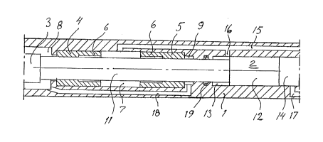
Water driven hammer device comprising a machine housing (1) and a hammer piston movable to-and-fro in the machine housing.
The hammer piston is guided in the machine housing in two guides (4, 5) arranged at a distance from each other. The guides are made
with two parts with different inner diameters. The parts (6) with the largest inner diameters on the guides are turned towards each othe.
The room (7) between the guides is pressurized and the chambers on the other side of the guides are kept at a lower pressure so that a flow
is obtained through the guides for centering the hammer piston in the machine housing so that the hammer piston does not seize.


French Abstract

Dispositif de martelage actionné par l'eau comportant un carter de machine (1) et un piston de martelage qui se déplace en va-et-vient dans le carter. Le piston de martelage est dirigé dans le carter par deux glissières (4, 5) disposées à une certaine distance l'une de l'autre. Les glissières sont construites avec deux parties dont les diamètres internes sont différents. Les parties (6) sur les glissières avec les diamètres les plus grands sont tournées l'une vers l'autre. L'espace (7) entre les glissières est mis sous pression, et la pression des chambres de l'autre côté des glissières est maintenue à un niveau plus faible de façon à obtenir un courant dans les glissières pour centrer le piston de martelage dans le carter de la machine et pour que le piston ne fige pas.

Claims

Note: Claims are shown in the official language in which they were submitted.


Claims:

1. Water driven hammer device comprising a machine housing (1), a
hammer piston (2) movable to-and-fro in the machine housing for impacting a tool (3)
inserted into the machine housing and two guides (4,5) arranged at a distance from
each other in the machine housing (1) for guiding the movement of the hammer
piston, c h a r a c t e r i z e d in that said guides (4,5) comprise at least two parts
with different inner diameters, that the part (6) with the largest inner diameter on each
guide (4,5) is positioned closest to the other guide, that a room (7) between the two
guides (4,5) is pressurized and that a chamber (8,9) on the other side of each guide
(4,5) is kept at a lower pressure than said room (7).

2. Water driven hammer device comprising a machine housing (1), a
hammer piston (2) movable to-and-fro in the machine housing for impacting a tool (3)
inserted into the machine housing and two guides (4,5) arranged at a distance from
each other in the machine housing (1) for guiding the movement of the hammer
piston, c h a r a c t e r i z e d in that said guides (4,5) comprise at least two parts
with different inner diameters, that the part (6) with the largest inner diameter on each
guide is positioned furthest away from the other guide, that a room between the two
guides is kept at a reduced pressure and that a chamber on the other side of each
guide is pressurized

Description

Note: Descriptions are shown in the official language in which they were submitted.


CA 02208012 1997-06-17
WO 96/19324 PCT/S1~95101471


Water driven h~mmer device

The present invention relates to a water driven hammer device. More particularly the
invention relates to the guiding of a h~mmer piston movable to-and-fro in the harnmer
device.

In previously known water driven h~mmer devices one has had problems with the
service life because metallic contact between the h~mmer piston and the m~hine
housing has resulted in the seizure of the hammer piston res--lting in damages on the
h~mmer piston and the m~l~hine housing.

The present invention, which is defined in the subsequent claims, aims at achieving a
water driven hammer device with subst~nti~lly increased service life. This is achieved
by ce.~c, ;.lg the hammer piston in the machine housing so that the driving head of the
h~mmer piston does not come into metallic contact with the m~hine housing. The
centering is achieved by means of a special design of the guides for the hammer
piston in combination with the l~rt;S:iule conditions at the guides.

An embodiment of the invention is described below with reference to the appendeddrawing which schematically shows a section through a part of a water driven
hammer device according to the invention.

The water driven hammer device shown in the drawing comprises a machine housing
1 in which a h~mmer piston 2 is movable to-and-fro. The h~mmer piston comprises a
piston rod 11 and a piston head 12. The piston rod 11 is inten-le~l for impacting a tool
3 inserted into the machine housing 1. The h~mmer piston 2 is driven to-and-fro by
~Itern~tely connecting room 14 to a source of high lJle~i:iUle water or to a low pressure
via channel 17 in the usual way. Room 13 is via ch~nn~l~ 15, 16 continuousl~
p~es~uli~ed in the shown example. It is also possible to supply room 13 with an
alternating pressure in a known manner. The piston rod 11 of the hammer piston is
guided in the m~hine housing 1 by two guides 4 and 5 which are arranged at a
distance from each other in the machine housing 1. The shown guides are made with
two parts of different inner diameter. The parts 6 with the largest inner diameter are

CA 02208012 1997-06-17
WO 96/19324 PCl[/SE95/01471

turned towards each other. The room 7 between the guides is ~lec~." ;~cl via thechannel 15. The channel 15 may contain a not shown restriction in order to obtain a
suitable level of the plCS:jllre in room 7. The chamber 8 is connectecl to a lower
UI~ than the l.ies~ in room 7. The chamber 9 is via channel 18 connected to
chamber 8. A seal 19 is arranged in the m~rhine housing to St;~l~lldle chamber 9 from
the room 13. In a practical example the distance belw~ll the two guides is about 300
mm and the play between the piston rod 11 and the guides 4 and 5 of the order of0.02-0.03 mm. The play at the larger diameter is about the double or somewhat less.
This design of the guides in combination with the ~le~ e in room 7 and the lowerpl~s~ e in chambers 8, 9 gives a pressure and a flow between the piston rod 11 and
guides 4, 5 which causes a precise centering of the h~mmer piston 2 in the guides.
Through this it is avoided that the piston head 12 of the hammer piston comes into
contact with the m~rhine housing 1 in spite of the play between the piston head and
the m~rhine housing being small to avoid ullnecessa~y leakage across the piston head.

The guides have in the shown example two parts with dirr~lenl diameters. They can
also be made with several steps or for inct~nr.e be conical or have another form as
long as a centering pre~ c; and flow is achieved in the slot between the piston rod
and the guide.

As an alternative to what has been described above one can turn the guides 4 and 5
and ~les~lll;7~ the chambers outside the guides and keep the room between the guides
at a lower pressure, whereby the flow through the slots between the guides and the
hammer piston is directed in the opposite direction.

The h~mmer device shown is a down the hole drilling macchine. The invention can
also be used in top h~mmer.~

Representative Drawing
A single figure which represents the drawing illustrating the invention.
Administrative Status

For a clearer understanding of the status of the application/patent presented on this page, the site Disclaimer , as well as the definitions for Patent , Administrative Status , Maintenance Fee  and Payment History  should be consulted.

Administrative Status

Title Date
Forecasted Issue Date Unavailable
(86) PCT Filing Date 1995-12-07
(87) PCT Publication Date 1996-06-27
(85) National Entry 1997-06-17
Examination Requested 2002-11-22
Dead Application 2006-07-06

Abandonment History

Abandonment Date Reason Reinstatement Date
2005-07-06 R30(2) - Failure to Respond
2005-07-06 R29 - Failure to Respond
2005-12-07 FAILURE TO PAY APPLICATION MAINTENANCE FEE

Payment History

Fee Type Anniversary Year Due Date Amount Paid Paid Date
Registration of a document - section 124 $100.00 1997-06-17
Application Fee $300.00 1997-06-17
Maintenance Fee - Application - New Act 2 1997-12-08 $100.00 1997-11-26
Maintenance Fee - Application - New Act 3 1998-12-07 $100.00 1998-11-17
Maintenance Fee - Application - New Act 4 1999-12-07 $100.00 1999-11-17
Maintenance Fee - Application - New Act 5 2000-12-07 $150.00 2000-11-14
Maintenance Fee - Application - New Act 6 2001-12-07 $150.00 2001-11-09
Maintenance Fee - Application - New Act 7 2002-12-09 $150.00 2002-11-06
Request for Examination $400.00 2002-11-22
Maintenance Fee - Application - New Act 8 2003-12-08 $150.00 2003-11-07
Maintenance Fee - Application - New Act 9 2004-12-07 $200.00 2004-11-04
Owners on Record

Note: Records showing the ownership history in alphabetical order.

Current Owners on Record
ATLAS COPCO ROCK DRILLS AB
Past Owners on Record
EKWALL, BERNDT
WIJK, GUNNAR
Past Owners that do not appear in the "Owners on Record" listing will appear in other documentation within the application.
Documents

To view selected files, please enter reCAPTCHA code :


To view images, click a link in the Document Description column. To download the documents, select one or more checkboxes in the first column and then click the "Download Selected in PDF format (Zip Archive)" or the "Download Selected as Single PDF" button.

List of published and non-published patent-specific documents on the CPD .

If you have any difficulty accessing content, you can call the Client Service Centre at 1-866-997-1936 or send them an e-mail at CIPO Client Service Centre.


Document
Description 
Date
(yyyy-mm-dd) 
Number of pages   Size of Image (KB) 
Representative Drawing 1997-11-18 1 11
Abstract 1997-06-17 1 56
Description 1997-06-17 2 95
Cover Page 1997-11-18 1 50
Claims 1997-06-17 1 34
Drawings 1997-06-17 1 20
Assignment 1997-06-17 5 201
Assignment 1997-06-17 7 272
Prosecution-Amendment 2002-11-22 1 42
Prosecution-Amendment 2005-01-06 2 47