Note: Descriptions are shown in the official language in which they were submitted.
CA 02208146 1997-06-06
WO 96/19292 PCT/N095/00238
1
Measuring Apparatus
This invention relates to an apparatus for measurement
of the position of an interface between two fluids in a
centrifuge rotor during rotation, comprising an electric or
magnetic sensor mounted internally on a wall in the centri-
fuge rotor, and means for contact-free and intermittent
transmission of measurement signals from the sensor to a
stationary measuring unit outside the centrifuge rotor.
Of particular interest to this invention is measurement
in centrifuges for the separation of fluids obtained when
producing oil from subsurface formations, including offshore
oil production. In many cases during such production there
will also be obtained water and gas together with the oil.
In centrifuges used for separation of the fluid fractions it
is of great importance to be able to measure the level of
the water layer and the oil layer in the centrifuge rotor,
i.e. in relation to the interior wall of the rotor. A high
degree of accuracy is desired in this level measurement,
i.e. measurement of the position of the interface between
the fluids or media. Specifically it is important to be
able to measure the position of the interface between water
and oil with high accuracy.
Accurate measurement of position or level in this
connection has been found to be difficult however, because
of sources of error and disturbance factors, perhaps in
particular the fact that the level of the interface of
interfaces in a centrifuge rotor during rotation, may vary
somewhat such as in consequence of the through-flow of
fluids in the axial direction of the rotor. Also other
factors can have influence on the measurement, for instance
a varying salinity of the water, capillary effect and so
forth. These factors or circumstances may be influenced
either in a favourable or in an unfavourable direction under
the high acceleration forces to which the fluids are
subjected in the centrifuges concerned, for example 3000 G.
Another consideration of significance is the response time
for the measurements, since quick changes of the interface
SUBSTITUTE SHEET (RULE 26)
CA 02208146 1997-06-06
WO 96/19292 PCT/N095/00238
2
level in the centrifuge rotor may require quick adjustment
or other precautions from an operator or a surrounding
system.
From Swiss patent specification 653,129 there is known
a measurement apparatus as stated in the introductory
paragraph above. This known apparatus, however, will not
result in sufficiently accurate measurement as required
according to the above discussion, especially not in view of
the disturbing factors or circumstances mentioned.
Moreover reference can be made to German patent speci-
fication 2.914.423 relating to a sentrifuge with means for
optical measurements through cells incorporated in the
sentrifuge rotor. There are also shown indications outside
the sentrifuge rotor for measuring or controlling the rot-
ational velocity of the rotor.
What is novel and specific in the apparatus according
to the invention in the first place consists therein
that the sensor has such an extension in the radial
direction of the rotor that the sensor penetrates said
interface,
that the sensor comprises an active electronic circuit
adapted to store measurement values that are recorded during
at least a portion of a revolution of the rotor, before said
transmission of corresponding measurement signals to the
measuring unit, and
that electric power supply to the electronic circuit is
provided for by generator means comprising a stationary
magnet near the centrifuge rotor and a coil mounted in the
rotor so that a voltage is induced in the coil, during move-
ment past the magnet by rotation of the rotor, and the coil
is connected to the electronic circuit.
A substantial advantage of the solution stated here,
consists therein that the measurement can represent an
average of level values over a portion of a revolution of
the rotor or the container, or possibly several revolutions.
This can be a fraction of a revolution, but normally in
practice it will be convenient to transmit measurement
signals to the measuring unit once for each revolution of
SUBSTITUTE SHEET (RULE 26)
CA 02208146 1997-06-06
WO 96/19292 PCT/N095/00238
3
the centrifuge rotor. The invention makes it possible to
measure the position of the interface between water and oil
with an accuracy at the order of magnitude of 0.1 mm.
As regards the basic principle of measurement in the
sensor, this may be a capacitive measurement principle, as
in the above mentioned Swiss patent specification, or the
measurement may be based on other physical parameters, such
as magnetic properties of the fluids concerned.
Although the primary and particularly interesting use
of the invention relates to centrifuges for oil separation,
also other fluids may be of interest.
In the following description, the invention shall be
explained more closely with reference to the drawings, in
which:
Fig. 1 schematically and in principle illustrates the
function of an apparatus according to the inven-
tion, associated with a centrifuge,
Fig. 2 in enlarged cross-sectional view shows a part of
the centrifuge housing and the rotor in Fig. 1,
with the associated measurement apparatus,
Fig. 3 schematically shows important components in an
embodiment of the sensor in the measurement appa-
ratus according to Figs. 1 and 2, with three sur-
rounding fluids, i.e. water, oil and gas,
Fig. 4 shows a simplified electrical system or block dia-
gram of the whole measurement apparatus as illus-
trated in Fig. 1,
Fig. 5 schematically shows a particularly advantageous
oscillator circuit which can be used in the system=
of Fig. 4,
Fig. 6 shows an example of a practical embodiment of a
sensor, partially in cross-sectional view and
partially in longitudinal section, and
Fig. 7 shows a much enlarged and cross-sectional view of
a capacitive measuring element which can be
incorporated in a sensor as illustrated, inter
alia, in Fig. 6.
Fig. 1 shows a portion of the circumference of a
SUBSTITUTE SHEET (RULE 26)
CA 02208146 1997-06-06
WO 96/19292 PCT/N095100238
4
centrifuge rotor 2 being provided with two measuring sensors
4 and 4 '. Preferably these sensors are located at an
angular spacing of 180 from each other, i.e. diametrically
opposite in the rotor. It is obvious that the number of
sensors in a centrifuge rotor can be one, two or more. An
interface iX between two fluids in the rotor 2 is also
indicated in Fig. 1. In the sensor 4 there is schematically
shown a measuring element 25 which can be adapted to measure
the position of the interface iX. Further, in the sensor 4
there is shown a block 8 which represents an electronic
circuit. At one side this circuit is connected to the
measuring element 25 and at the other side to one part 5A of
a transmission device for measurement signals from the
sensor 4 to a stationary measuring unit. In Fig. 1 the
stationary measuring unit is shown as a block 7 in a
measuring housing 10 which also comprises another part 5B of
the transmission device just mentioned, as well as a magnet
device 11 which is incorporated in a generator, as will be
described more closely below with reference to Fig. 2.
For simplicity, the sensor 4 in Fig. 1 is shown with
only one measuring element 25 for measuring the position of
an interface iX, but as will appear from the following
description, it can be an advantage in practice for the
primary use in water-oil-gas separation to employ two
measuring element parts at a mutual spacing in the
longitudinal direction of the sensor, i.e. at different
radial positions in the centrifuge rotor 2.
The measuring unit 7 in housing 10 according to Fig. 1
is connection to an external control or regulating system 30
which comprises at least one output 30A to control equipment
for the centrifuge.
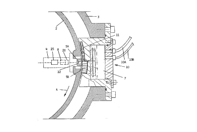
Fig. 2 somewhat more in detail and in cross-section shows the centrifuge rotor
and the cylindrical wall 2 there-'
of, as well as a surrounding housing 3. As in Fig. 1 the
sensor 4 in Fig. 2 is shown schematically with the measuring
element 25, the electronic circuit 8 and more specifically-
the transmission part or head 5A which is located at the end
of sensor 4 which approaches the outer circumference of
SUBSTITUTE SHEET (RULE 26)
CA 02208146 1997-06-06
WO 96/19292 PCT/N095/00238
rotor 2. Thus, in this embodiment the sensor 4 is mounted
in a bore in the rotor wall 2 so that the radially outer end
of the sensor 4 comprising, inter alia, the transmission
head 5A, can cooperate with stationary members or devices
5 located in the measuring housing 10, which for example by
means of bolts is attached to the centrifuge housing 3. In
addition to the head 5A there is also shown in the end
portion of sensor 4 a coil 12 which is incorporated in the
generator device mentioned above, and which like head 5A is
electrically connected to the electronic circuit S.
The measuring unit 7 in Fig. 2 as illustrated can com-
prise a board or substrate carrying the necessary circuits
with electronic components and connections. Also the
stationary transmission head 5B adapted to cooperate with
head 5A in sensor 4, can be considered to belong to
measuring unit 7.
The arrow A in Fig. 2 indicates the direction of rota-
tion of rotor 2. In front of the stationary head 5B as seen
in the rotational direction there are arranged a row of
magnets 11, being preferably permanent magnets, for coope-
ration with the coil 12 at the end portion of the sensor 4.
Accordingly, when the rotor 2 rotates and because of the
magnets 11, there will be induced a voltage in coil 12, and
thereby a sufficient amount of electrical energy will be
generated, for supplying the electronic circuit 8 for the
operation thereof. Such power supply is necessary because
the electronic circuit 8 comprises active elements adapted
to store measurement values being recorded by measuring
element 25 during rotation.
It is preferred that coil 12 is wound on a ferrite
core. When the sensor moves past the permantent magnets 11
there will be generated an alternating current in the coil.
In a manner known per se this alternating current can be
rectified and filtered before it is applied to the
electronic circuit 8. These components in a circuit 20
which is comprised by the generator device, shall be
discussed more closely below in connection with Fig. 4.
It is clear that the high rotational speed, which can
SUBSTITUTE SHEET (RULE 26)
CA 02208146 1997-06-06
WO 96/19292 PCT/N095/00238
6
involve a linear velocity of the rotor circumference of 100
m/s, to a high degree contributes to a sufficient induced
voltage and thereby generated power in the generator device
as a whole.
Of great significance in this connection is also the
gap or spacing between the outer rotor wall 2 with the
sensor end portion comprising the head 5A and the coil-
ferrite core 12, and the adjacent curved surface of
measuring housing 10, in particular the permanent magnets 11
therein. For example the air gap can be of an order of
magnitude of 2 mm. The basic function of the arrangement
described here however, will be the same and in practice
fully possible also with a somewhat wider gap.
An additional important factor in this connection is
the fact that the row of permanent magnets 11 has a certain
extension in the circumferential direction with respect to
the rotor rotation, namely so that the magnet device 11 has
a significantly larger extension in the circumferential
direction than the cooperating coil 12 with its associated
ferrite core. Therefore the electrical power supply for the
electronic circuit 8 takes place over a distance
corresponding broadly to the lenght of the magnet device 11
in the circumferential direction. This constitutes only a
very small fraction of the whole circumference, but as will
be explained more closely below with reference to Fig. 4,
the electronic circuit 8 comprises means for storing the
electrical energy from the generator during a sufficiently
long time for the required'operation of the electronic
components.
The transmission or receiver head 5B is correspondingly .
extended in the circumferential direction like the magnet
device 11, as will be seen from Fig. 2. This contributes to
facilitating the signal transmission from the transmitter
head 5A in rotor 2 during the high speed rotation thereof
past head 5B. In view of a possible disturbance or
influence on receiver head 5A from the main parts 11 and 12
of the generator device, it is an advantage according to a
particular embodiment, that the magnetic field direction for
SUBSTiTUTE SHEET (RULE 26)
CA 02208146 1997-06-06
WO 96/19292 PCT/N095/00238
7
the inductive transmission between heads 5A and 5B, is
normal to the magnetic field direction in generator device
11-12.
Advantageously, both magnetic heads 5A and 5B in the
transmission device can comprise ferrite cores, such as a
row of U-cores arranged in receiver head 5B.
For the primary and specific use in centrifuges for
separation of water, oil and gas, it is important that the
complete apparatus and structure has an explosion-safe de-
sign. A safety precaution in this connection is to let the
power supply from generator device 11-12 to electronic
circuit 8 take place through zener barriers (not shown).
Another design feature aiming at such safety, is potting of
the electrical and electronic components, which also leads
to increased reliability and secure operation.
From measuring housing 10 in Fig. 2 there are shown two
leads or cables l0A and lOB for conveying transmitted and
possibly somewhat processed measurement signals to the above
mentioned control or regulating system 30, which is shown
schematically in Fig. 1, where the connection 10A-B corres-
ponds to the leads or cables just mentioned.
Fig. 3 illustrates somewhat more in detail but anyhow
schematically, the components being incorporated in sensor 4
in a practical embodiment thereof. One end (to the left in
Fig. 3) of sensor 4 is mounted in the rotor wall 2 and pro-
jects (to the right) into three fluids 1A, 1B and 1C which
because of the rotation are separated into layers as shown.
Thus, in the example concerned fluid 1A can be. water,and
fluid 1B oil, with an intermediate interface 1X as mentioned
above. Between the oil layer 1B and the third fluid 1C
which is here a gas, there is another interfac.e 1Y.
~' ' _ -- - - - - - - - -
In sensor 4 there is shown a first capacitive measuring
element 25 for the position of the interface 1X, and a
second capacitive measuring element 26 for the interface 1Y.
The magnetic transmitter head 5A and the generator coil 12
are shown at the radially outer end of sensor 4, i.e. the
end which is mounted in rotor wall 2. Coil 12 is connected
to generator circuit 20.
SUBSTITUTE SHEET (RULE 26)
CA 02208146 1997-06-06
WO 96/19292 PCT/N095100238
8
In a purely block schematic manner there is for sensor
4 in Fig. 3 shown components or blocks incorporated in
electronic circuit 8, i.e. in the first place a transmitter
circuit 41 and a frequency counter 42 being responsive to a
capacitance value from measuring elements 25 and 26. In the
second place there are shown a crystal oscillator 44 and two
further oscillator circuits 46 and 48 being each associated
with a measuring element 25 and 26, respectively.
Measuring element 25 for the water-oil interface 1X
will have a varying capacitance dependent upon how large
proportion of the surface area of the measuring element
against the fluids, is covered with water, since the water
lA as indicated in Fig. 3, constitutes one of the two
electrodes in a capacitor formed by measuring elements 25.
In measuring element 26 however, there are incorporated two
permanent capacitor plates or electrodes, whereby the
intermediate dielectric to a larger or smaller degree
consists of oil or gas, so that the difference in dielectric
constant between oil and gas leads to variations in the
capacitance value of measuring element 26.
The electronic main components being shown in a simpli-
fied way in the arrangement of Fig. 3, are illustrated some-
what more in detail in Fig. 4, where the main parts of the
measurement apparatus in the form of sensor 4, measuring
unit 7 and external control system 30, can be seen.
Measurement values represented by the capacitance of
measuring element 25 serves as an input signal to electronic
circuit 8, which comprises a capacitance-frequency converter
46, frequency counter 42, which possibly can incorporate a-
processing part 42A, the drive or transmitter circuit 41 and
the actual transmitter magnetic head 5A. Besides, the cir-
cuit 8 comprises the reference oscillator 44 which
preferably is crystal controlled, and moreover a time
control circuit 40.
A preferred embodiment of the capacitance-frequency
converter 46 is shown somewhat more in detail in Fig. 5. As
shown therein, the converter circuit can be considered to
constitute a self-compensating oscillator based on a phase-
SUBSTITUTE SHEET (RULE 26)
CA 02208146 1997-06-06
WO 96/19292 PCT/N095/00238
9
locked loop. This includes a phase detecter 43, a filter 45
and two identical voltage controlled oscillators 47 and 49,
each being responsive to a separate measuring capacitor,
namely the reference element or capacitor 37 and the measur-
ing capacitor 35 respectively, in measuring element 25 as
shown for example in Fig. 3. A converter circuit 48 corres-
ponding fully to circuit 46 is provided for measuring
element 26. For the sake of clarity only converter circuit
46 is shown in Fig. 4.
The manner of operation of the circuits described can
be explained briefly as follows: The capacitive elements
are frequency-determining elements in the self-compensating
oscillator or converter circuit 46, and in counter circuit
42 the freqency is converted to a digital output signal upon
counting of the frequency during an exactly determined time
interval. The generation of the digital output signal,
possibly combined with further signal processing, can be
considered to take place in the processing part 42A shown,
which can be more or less integrated with the frequency
counter 42.
The exact determination of the counting period or
interval takes place by means of crystal oscillator 44. The
capacitive measuring element, such as element 35 at a given
capacitance value will result in an output frequency from
the oscillator depending on ambient temperature, supply
voltage and ageing of circuit components being incorporated.
In order to compensate for such and other sources of error,
use is made of the two identical oscillators 47 and 49,
being connected to the reference capacitive element 37 and
the measuring capacitor element 35 respectively, as
mentioned above. Ideally the output frequency of oscillator
47 is stable, except for possible unwanted drift. If the
two oscillators 47 and 49 can be regarded as identical and
being preferably built on the same silicon chip, it can be
assumed that the drift will also be identical for the two
oscillator circuits. Variations in the output frequency
from the "stable" oscillator 47 can therefore be used to
compensate for drift in the measuring oscillator 49. Best
SUBSTITUTE SHEET (RULE 26)
CA 02208146 1997-06-06
WO 96/19292 PCT/N095/00238
results with respect to stability are obtained with two
voltage controlled oscillator circuits 47 and 49, of which
the reference oscillator 47 is incorporated in the phase-
locked loop mentioned above (Fig. 5) against a reference
5 frequency from crystal oscillator 44. Thereby a compensated
working point is established for the measuring oscillator
49.
For transmitting the measurement signals obtained, to
measuring unit 7 in short time during movement of sensor 4
10 past the measuring unit 7, it is preferred to convert the
measurement signals to digital words as already mentioned.
A word length of 12 bits has been found to be suitable.
This makes possible a maximum resolution of 4096 steps,
which is more than sufficient. In actual practice
electronic circuit 8 comprises three parallel frequency-
digital converters, i.e. for water level, oil level and
temperature respectively, since it is also of interest to
measure the temperature of the fluid mentioned, in a
centrifuge rotor during operation. The three resulting
digital words of 12 bits each, are read out consecutively
through magnetic heads 5A and 5B as previously described.
Storing of measurement values being recorded through at
least a proportion of a resolution of the centrifuge rotor,
is effected by controlling the counting interval, which can
for example constitute 10% less than the time for a complete
revolution. Accordingly, the output level will represent an
average value of the various levels of the fluids in the
centrifuge, measured over 90% of the centrifuge circumfe-
rence. Details regarding the associated digital signal
processing in this connection, will be apparent to experts
in the f ield and will not be discussed more in detail here.
In order to secure that the signal transmission from the
rotor takes place at a correct angular position, a starter
pulse is derived from the generator device 11-12 so as to
indicate movement past the last permanent magnet 11.
Concerning the generator circuit in connection with
coil 12, Fig. 4 shows a rectifier bridge 22, a filter 23 and
a voltage regulator 27.
SUBSTITUTE SHEET (RULE 26)
CA 02208146 1997-06-06
WO 96/19292 PCT/N095/00238
11
Measuring unit 7 comprises a discriminator circuit 15
between magnetic head 5B and a line driver or amplifier
circuit 17, for conveying the digital measurement signals
further along a lead 10A to the control system 30. From
control system 30 the lead lOB conducts electrical power to
measuring unit 7. Preferably zener barriers 50A and 50B are
utilized in the control system 30 against the connecting
leads 10A and lOB for measuring unit 7. This is preferred
in view of the risk of explosion. In the control system or
block 30 there are moreover included circuits being more or
less near at hand, such as a current supply circuit 51, an
amplifier circuit 52 and a microcontroller or processor 53
as well as an additional amplifier 54, whereby an electrical
interface is indicated at 55 for connections to controls,
alarms and so forth associated with the operation of the
centrifuge.
In the example of a more practical embodiment of a
sensor design as shown in Fig. 6 with accompanying cross-
sectional views 6A and 6B as well a longitudial sectional
view 6C, sensor 4 has an encasing 61 with a streamlined
outer cross-sectional shape as will appear from the
crossection Figs. 6A and 6B. The cross-sectional shape
here corresponds to a flow of the fluids in the axial
direction of rotor 2.
In Fig. 6 the same three fluids 1A, 1B and 1C are shown
as in Fig. 3 At the two interfaces between the fluids there
is here in particular indicated examples of maximum levels,
namely lXmax and lYmax respectively, as well as minimum
levels, namely lXmin and lYmin respectively. As seen from
Fig. 6 measuring element 25 comprises a capacitive electrode
member or surface 35 adapted to cover the range of variation
(lXmin-lXmax) of interface iX between fluids lA and 1B, and
besides a reference electrode 37 adapted to be always
located in the outer fluid lA during operation of the
centrifuge. Quite correspondingly measuring element 26 has
a measuring part or electrode surface 31 for the interface
1Y between fluids 1B and 1C, and a reference electrode 32
adapted to be immersed in fluid iB during operation. This
SUBSTITUTE SHEET (RULE 26)
CA 02208146 1997-06-06
WO 96/19292 PCT/N095/00238
12
arrangement with reference electrodes 32 and 37 according to
the invention constitutes an advantageous solution for the
purpose of eliminating certain sources of error. This has
been explained already above with reference to the block
diagram of Fig. 4.
Fig. 6A in cross-sectional view shows how the
measuring element 26 is arranged in relation to a through-
running slit 36 in sensor 4, corresponding to the axial flow
direction through the rotor as mentioned above, whereby the
two fluids 1B and 1C concerned, i.e. oil and gas
respectively, in the primary field of use as mentioned, will
enter into the slit 63 without displacement or unfavourable
influence of the interface position to be measured, because
of the flow through slit 63. The above fixed electrodes in
measuring element 26 are located each on one and the other
side of slit 63.
The cross-sectional view of Fig. 6B shows the
measuring element 25 which faces outwards from one side wall
of encasing 61 for direct cooperation with the surrounding
fluid 1A, for example water, or fluid iB which in the
present example is oil. Behind measuring element 25 in Fig.
6B the abovo- electronic circuit 8 has been shown purely
schematically and located within an inner cavity in encasing
61. See also the corresponding location in the longitudinal
section of Fig. 6C. The sensor encasing or housing 61 can
be manufactured conveniently by casting of titanium, which
combines strength and low weight.
Finally Fig. 7 at an enlarged scale shows an embodiment
of the capacitive measuring element 25 mounted at a surface
of encasing 61, which is here shown only partially and in
cross-section. Measuring element 25 is built up on a p.late-
shaped substrate 50, preferably a ceram or other stable
material. On the main surface 51 facing outwards, substrate
50 is provided in the first place with an electrode element
or coating 35, as already explained above, and besides with
a reference electrode coating 37. This arrangement
substantially corresponds to what is also shown with respect
to measuring element 25 in Fig. 6. The opposite main
SUBSTITUTE SHEET (RULE 26)
CA 02208146 1997-06-06
WO 96/19292 PCT/N095/00238
13
surface 52 of substrate 50 preferably as a conductive
coating 54 which constitutes a ground plane. This
contributes to making the whole measuring element 25 more
well defined as to electrical conditions and also
independent of the surroundings in encasing 61.
In front of the electrode coatings 35 and 36 and
preferably intimately engaging these there is provided an
electrically insulating plate 55 as a window against the
fluids surrounding the sensor encasing 61. As discussed
above the most frequent employment of the sensor will
involve the presence of oil or water at the outside of plate
55. In such practical use the plate will be subjected to
very severe external stresses, such as the very high
pressures mentioned above, wear because of particles which
may be contained in the fluids, and a high G-load. A
preferred material in plate 55 is sapphire, which is wear-
resistant and has the required mechanical strength in this
measuring element structure.
The manner of operation of such a capacitive measuring
element has been discussed already above, whereby a larger
or smaller water coverage of the electrode 35 results in
larger or tmaller effective capacitor areas with the
intermediate plate 55 as the dielectric. It may be an
advantage to let the electrode 35 have a surface shape with
a tapering width so that the capacitance variation will be
linear in relation to changes of water level, i.e. the
position of the interface between water and oil.
SUBSTITUTE SHEET (RULE 26)