Note: Descriptions are shown in the official language in which they were submitted.
CA 02208277 2000-02-08
a
-1-
NOZZLE FOR EXTRUDING FLOWABLE MATERIAL
FIELD OF THE INVENTION
This invention relates to a glazing unit having
three or more glass sheets, and, in particular to a triple
glazed unit having a pair of outer glass sheets separated by
an edge assembly having low thermal conductivity, the edge
assembly including a spacer arrangement for supporting a glass
sheet between the outer glass sheets, and method of making,
and nozzle for use in the fabrication of the triple glazed
unit.
BACKGROUND OF THE INVENTION
European Patent Application Publication Number 0 475
213 A1 published 18.03.92 Bulletin 9212 (hereinafter "The EP
Application) based on U.S. Patent No. 5,177,916 issued January
12, 1993 teaches a glazing unit having an edge assembly having
low thermal conductivity and a.method of making same. In
general, the EP application teaches an insulating unit having
a pair of glass sheets about an edge assembly to produce a
compartment between the sheets. The edge assembly has a U-
shaped spacer that is moisture and/or gas impervious, and has
materials selected and sized to provide the edge assembly with
a predetermined RE-value (as defined and determined in the
disclosure of The E application). The E Application further
discloses a triple glazed unit having a low thermal conducting
edge.
U.S. Patent No. 4,149,348 teaches a technique for
making a triple glazed unit. In general, the triple glazed
unit introduces a pair of outer glass sheets separated by a
spacer-dehydrator element, or metal spacer, having a groove to
maintaining a third glass sheet between the outer two glass
sheets.
CA 02208277 2000-02-08
-2-
Although the triple glazed unit taught in U.S.
Patent No. 4,149,348 is acceptable, there are limitations.
More particularly, the spacer-dehydrator element is
structurally stable and is formed with a groove prior to its
use. The spacer has desiccant therein; therefore, it is stored
in a dry environment to prevent adsorption of moisture by the
desiccant. The metal spacer has to be formed to have a groove;
the additional forming increases the fabrication cost of the
spacer. Further, the groove formed in the spacer disclosed is
U.S. Patent No. 4,149,348 maintains the third glass sheet
spaced from the outer sheets; therefore, the groove has to be
properly sized to prevent movement of the inner sheet relative
to the outer sheets.
As can be appreciated, it would be advantageous to
provide an insulating unit having three or more sheets that
does not require storage of prefabricated materials e.g. a
spacer-dehydrator element having a groove, does not require
shaping the spacer to have a groove, and does not depend
solely on the groove formed in the spacer to secure the
intermediate sheet in position.
SUMMARY
This disclosure relates to a glazing unit having at
least three glass sheets. The unit includes a spacer having a
receiving surface to maintain the glass sheets in spaced
relationship to one another. In one embodiment of the
invention, the spacer has a base, a first wall and a second
wall each extending upward from the base to provide the spacer
with a generally U-shaped cross section with the receiving
surface between the walls. The glass sheets are secured to the
spacer, e.g. by a moisture and/or gas impervious adhesive on
outer surfaces of the walls of the spacer to provide sealed
compartments between the outer glass sheets e.g. a sealed
compartment between one of the outer sheets and the
CA 02208277 2000-02-08
i
-3-
intermediate sheet and a sealed compartment between the other
outer sheet and the intermediate sheet. A layer of a flowable,
pliable material has a generally U-shape cross section to
provide a groove to receive marginal edge portions of the
third or intermediate glass sheet. Facilities are provided to
maintain the intermediate sheet in a substantially fixed
relationship to the outer glass sheets. In one embodiment of
the invention, the wall portions of the spacer at selected
corners of the finished unit are bent toward one another and
spaced a sufficient distance to receive the intermediate glass
sheet therebetween. The wall portions of the spacer bent
toward one another biases the pliable material on the
receiving surface of the spacer toward the intermediate sheet
to maintain the intermediate sheet in position.
In a further embodiment of the invention a desiccant
is provided in the pliable material, an insulating gas e.g.
argon gas is provided in the compartments formed by adjacent
sheets and the spacer, and/or the edge assembly including the
spacer, the adhesive and the pliable material have a RES-value
equal to or greater than 10 as measured using ANSYS.
The disclosure further relates to a method of making
an insulating glazing unit having at least three sheets
including the steps of providing two glass sheets having
substantially the same peripheral configuration and dimensions
and a spacer of a predetermined length having a receiving
surface. In one embodiment of the invention, the spacer is
formed by providing notches at selected positions on a flat
bendable substrate to provide opposed pair of notches defining
bend areas of the spacer. The flat substrate is shaped to
provide a spacer having a generally U-shaped cross section
defined by a first outer leg, a base and a second outer leg. A
shaped layer of a flowable material e.g. a pliable material or
a material that hardens after flowing and is dimensionally
stable, having a groove is provided on the receiving surface
of the spacer. The glass sheet or sheets to be positioned
between
CA 02208277 2000-02-08
a
-4-
the outer sheets has peripheral configurations similar to the
outer glass sheets and peripheral dimensions less than the
outer sheets. The spacer is positioned around the edge of the
intermediate sheet with the edges of the intermediate sheet in
the groove. The intermediate sheet is maintained in a
generally fixed position relative to the outer glass sheets by
the pliable material and/or the spacer. In one embodiment of
the invention, as the spacer having the U-shaped cross section
is positioned around the periphery of the third sheet, the
wall portions of the spacer at the bend areas are bent inward
toward one another urging the pliable material toward the
corner areas of the intermediate sheet. The layer of the
pliable material may have a desiccant mixed therein. The outer
glass sheets are secured to the outer surfaces of the legs of
the spacer by an adhesive, e.g. by a moisture and/or gas
impervious adhesive.
The disclosure still further relates to a nozzle to
deposit the shaped layer of the flowable material on the
spacer. The nozzle includes a platform having a shaping.tip or
member mounted therein. The shaping tip at a first end has
converging sides and at the opposite end has sides that are
generally parallel to one another. The elevation of the
shaping tip at the first end is different e.g. lower, than the
elevation of the shaping tip at the second end. Holes for
moving material therethrough are in the nozzle, e.g. one hole
on each side of the tip and one in the tip. The converging end
of the tip and the different elevations of the tip minimize,
if not eliminate, tailing when moving e.g. pumping of the
material has been discontinued.
The disclosure still further relates to an injector
arrangement for filling the compartments between the sheets
with an insulating gas.
Embodiments of the invention will now be described with
reference to the accompanying drawings.
CA 02208277 2000-02-08
-5-
BRIEF DESCRIPTION OF THE DRAWINGS
Fig. 1 is a frontal view of a triple glazed unit
embodying the invention.
Fig. 2 is the view taken along lines 2-2 of Fig. 1.
Fig. 3 is a view similar to the view of Fig. 2
illustrating another embodiment of an edge assembly.
Fig. 4 is a fragmented elevated view of a substrate
having portions removed prior to forming a spacer used in the
practice of the invention.
Fig. 5 is an elevated side view of a nozzle
embodying the invention for extruding a shaped layer of
adhesive on the base of a spacer.
Fig. 6 is a plane view of the tip of the nozzle
illustrating features embodying the invention.
Fig. 7 is a side view of the tip of the nozzle.
Fig. 8 is a view similar to the view of Fig. 6
illustrating another embodiment of a tip embodying the
invention.
Fig. 9 is a view similar to the view of Fig. 7
illustrating further details of the tip of Fig. 8.
Fig. 10 is a side elevated view of an injector
arrangement embodying the invention for filling the
compartments of a glazing unit with an insulating gas.
Fig. 11 is an end view of the injector arrangement
of Fig. 10.
Fig. 12 is a view illustrating the use of the
injector arrangement embodying the invention to fill a unit
having a single compartment with an insulating gas.
Fig. 13 is a view similar to the view of Fig. 12
illustrating the use of the injector arrangement embodying the
instant invention to fill a unit having two sealed
compartments.
CA 02208277 2000-02-08
s
-6-
Fig. 14 is a view similar to the view of Fig. 2
showing an insulating unit having three compartments embodying
the invention.
BRIEF DESCRIPTION OF THE PREFERRED EMBODIMENTS
The glazing unit embodying the instant invention
will be discussed having the edge assembly disclosed in the EP
Application which teachings are hereby incorporated by
reference. As will be appreciated the instant invention is not
limited to the configuration of the spacer disclosed therein,
and other spacer configurations may be used in the practice of
the invention to maintain the at least three spaced sheets in
spaced relationship to one another; i.e. prevent or minimize
movement of the intermediate sheet toward an outer sheet.
With reference to Figs. 1 and 2 there is shown a
glazing unit 20. With specific reference to Fig. 2 the unit 20
includes a pair of outer sheets 22 and 24 and an intermediate
sheet 26. The outer sheets 22 and 24 and the intermediate
sheet 26 are maintained in spaced relationship by an edge
assembly or spacer arrangement 28.
In the following discussion the sheets 22, 24 and
26 are referred to as glass sheets; however, as will become
apparent, the materials of the sheets are not limited to
glass and any one or all of the sheets may be made of any
similar or dissimilar material e.g. plastic, metal or wood.
Further, one or more of the sheets may be coated e.g. glass
or plastic transparent sheets may have an opaque coating of
the type used in making spandrels. Still further, one or
more of the glass or plastic transparent sheets may have an
environmental coating on one or more of the sheet surfaces
to selectively pass predetermined wavelength ranges of
light. More particularly, glass sheets may have coatings to
filter portions of the infrared range e.g. low E coatings
and/or coatings to reflect light e.g. reflective coatings.
Although not limiting to the invention, coatings disclosed
CA 02208277 2000-02-08
s r
_7_
in U.S. Patent Nos. 4,610,711; 4,806,220 and 4,853,256 may be
used in embodiments of the invention. Still further, one or
more of the glass sheets may be coated and or uncoated colored
sheets. Although not limiting to the invention, colored sheets
of the type disclosed in U.S. Patent Nos. 4,873,206;
5,030,593 and 4,792,536 may be used in embodiments of the
invention.
The outer glass sheets 22 and 24 may have the same
peripheral configuration and dimensions; however, as can be
appreciated, one outer glass sheet may be larger than the
other outer glass sheet and may have a different peripheral
configuration.
The edge assembly 28 includes a spacer 30 having a
generally U-shaped cross section as shown in Fig. 2, an
adhesive layer 32 on outer surfaces of outer legs 34 and 36 of
the spacer 30 and a shaped layer 38 of material (to be
discussed below) on inner surface 40 of base 42 of the spacer
30. A layer 44 of a material similar to or dissimilar from the
material of the layers 32 may be provided over outer surface
46 of the base 42 of the spacer 30 as shown in Fig. 2.
As can be appreciated, the configuration of the
spacer is not limiting to the invention and may have any cross
section provided it has a surface to receive the shaped layer
38 and the intermediate glass sheet 26. For example and with
reference to Fig. 3, there is shown a unit 50 having the glass
sheets 22 and 24 separated by an edge assembly 52 having the
adhesive layers 32 to secure the glass sheets 22 and 24 to
spacer 54. The spacer 54 may be made of wood, metal or plastic
having any cross sectional configuration and a receiving
surface 56 to receive the shaped layer 38 in a similar fashion
as the surface 40 of the spacer 30 of the edge assembly 28
shown in Fig. 2.
CA 02208277 2000-02-08
_8_
As discussed, the spacers 30 and 54 may be made of
any material and configuration that preferably provides
structural stability to maintain the outer glass sheets 22 and
24 in spaced relationship to one another when biasing forces
are applied to secure the glazing unit in a sash or a
curtainwall system. Further the spacers 30 and 54 should have
a substantially flat surface to receive the shaped layer 38.
Although the spacers 42 and 54 may be made of any material and
have any configuration provided it has a receiving surface, it
is preferred that the spacer have low thermal conductivity so
that the edge assembly 28 shown in Fig. 2, and the edge
assembly 52 shown in Fig. 3, have a low thermal conductivity
or high RES-value and are made of moisture and/or gas
impervious materials.
In regards to the edge assembly having a low thermal
conductivity, spacers made of aluminum conduct heat better
than spacers made of metal coated steels e.g. galvanized or
tin plated steel, spacers made of metal coated steels conduct
heat better than spacers made of stainless steels, and spacers
made of stainless steels conduct heat better than spacers made
of plastics. Plastic provides a better spacer from the
standpoint of low thermal conductivity; however, metal is
preferred for spacers because it is easier to shape and lends
itself more easily to automation than plastic.
The EP Application discusses in detail how RES-value
is determined and the contributions of the components of the
edge assembly to the RES-value. The following is a less
detailed discussion.
The heat loss through an edge of a unit is a
function of the thermal conductivity of the materials used,
their physical arrangement, the thermal conductivity of the
frame and surface film coefficient. Surface film coefficient
is transfer of heat from air to glass at the warm side of the
unit and heat transfer from glass to air on the cold side of
CA 02208277 2000-02-08
t r
_g_
the unit. The surface film coefficient depends on the weather
and the environment. Since the weather and environment are
controlled by nature and not by unit design, no further
discussion is deemed necessary. The frame or sash effect is
not relevant in the present discussion because the discussion
is directed to the thermal conductivity of the materials at
the unit edge and their physical arrangement.
The resistance of the edge of a unit to heat loss for an
insulating unit having sheet material separated by an edge
assembly is given by equation (1).
( 1 ) RHL = G1 + GZ + . . . + Gn + S1 + SZ + . . . + Sn
where RHL is the resistance to edge heat loss at the
edge of the unit in hour - °F/BTU/inch of unit
perimeter (Hr-°F/BTU-in.)
G is the resistance to heat loss of a sheet in
Hr-°F/BTU-in.
S is the resistance to heat loss of the edge
assembly in Hr-°F/BTU-in.
For an insulating unit having two sheets separated by a
single edge assembly equation (1) may be rewritten as
equat ion ( 2 ) .
(2) RHL = Gl + GZ + S1
The thermal resistance of a material is given by
equation (3).
(3) R = L/kA
where R is the thermal resistance in Hr-OF/BTU-in.
k is thermal conductivity of the material in
BTU/hour-inch-°F.
L is the thickness of the material as measured in
inches along an axis parallel to the heat flow.
A is the area of the material as measured in square
inches along an axis transverse to the heat flow.
The thermal resistance for components of an edge
assembly that lie in a line substantially perpendicular
CA 02208277 2000-02-08
s
-10-
or normal to the major surface of the unit is determined by
equation (4).
( 4 ) S = R1 + RZ + . . . + Rn
where S and R are as previously defined.
In those instances where the components of an edge
assembly lie along an axis parallel to the major surface of
the unit, the thermal resistance (S) is defined by the
following equation (5).
1
(5) R = 1 + 1 + ...+ 1
R~ R2 Rn
where R is as previously defined.
Combining equations (2), (4) and (5), the resistance
of the edge of the unit 20 shown in Fig. 2 to heat flow may be
determined by following equation (6).
1
( 6 ) RHL = R22 + R24 + 2832 + 2834 + 1 + 1- + 1
Ra2 R3s Raa
where RHL is as previously defined,
R22 and R29 are the thermal resistance of the glass
sheets,
R32 is the thermal resistance of the adhesive layer
32,
R94 is the thermal resistance of the adhesive layer
44,
R34 is the thermal resistance of the outer legs 34 of
the spacer 30,
R92 is the thermal resistance of the base 42 of
the spacer 30,
R38 is the thermal resistance of the adhesive
layer 38, and
R26 is the thermal resistance of the middle sheet 26.
For ease of discussion, equation (6) does not
consider the thermal conducting contribution of the
intermediate sheet 26. If the thermal conductivity
contribution of the intermediate sheet 26 were considered,
CA 02208277 2000-02-08
-11-
it is expected that the value of RHL in equation (6) would be
about 10% higher than the value calculated without considering
the contribution of the thermal conductivity of the
intermediate sheet 26. In the RES-value given in the
specification and claims the RES-value does not include the
contribution of the intermediate sheet 26.
Although equation (6) shows the relation of the
components to determine edge resistance to heat loss, Equation
6 is an approximate method used in standard engineering
calculations. Computer programs are available which solve the
exact relations governing heat flow or resistance to heat flow
through the edge of the unit.
One computer program that is available is the
thermal analysis package of the ANSYS program available from
Swanson Analysis Systems Inc. of Houston, PA. The discussion
of the edge resistance of the edge assembly (excluding the
outer glass sheets) will now be considered. The edge
resistance of the edge assembly is defined by the inverse of
the flow of heat that occurs from the interface of the glass
sheet 22 and adjacent sealant layer 32 at the inside side of
the unit to the interface of glass sheet 24 and adjacent
sealant layer 32 at the outside side of the unit per unit
increment of temperature, per unit length of edge assembly
perimeter (including the intermediate sheet). The outer glass
sealant interfaces are assumed to be isothermal to simplify
the discussion. Support for the above position may be found,
among other places, in the paper entitled Thermal Resistance
Measurements of Glazing System Edge-Seals and Seal Materials
Using a Guarded Heater Plate Apparatus written by J. L. Wright
and H. F. Sullivan ASHRAE TRANSACTIONS 1989, V.95, Pt.2.
In the discussion herein and in the claims, RES-
value is defined as the resistance to heat flow of the edge
assembly e.g. the edge assembly 28 in Fig. 2 and the edge
assembly 52 in Fig. 3, per unit length of perimeter.
CA 02208277 2000-02-08
-12-
The materials of the adhesive layers 32 and the
layer 44 are not limiting to the invention and are preferably
a material that is moisture and/or gas impervious to prevent
the ingress of moisture into the compartment between the
sheets. Although not limiting to the invention, butyl hot
melts of the type sold by H. B. Fuller e.g. H. B. Fuller 1191
may be used in embodiments of the invention. Units filled with
an insulating gas e.g. Argon preferably have the adhesive
layer 32 and the layer 44 of a moisture and/or gas impervious
material to maintain the insulating gas in the compartment
between the sheets 24, 26 and 26, 22. It is recommended that
the adhesive layer 32 or sealant layer 32 be thin and long to
reduce the diffusion of the insulating gas out of, the
compartments of the unit or atmosphere's gas into the
compartments of the unit. More particularly, increasing the
thickness of the layer 32 i.e. the distance between the glass
sheet and the adjacent leg of the spacer while keeping all
other conditions constant increases the diffusion rate, and
increasing the length of the layer 32 i.e. the distance
between the top of the outer leg of the spacer and the
peripheral edge of the sheets or the outer surface 46 of the
spacer 30 as viewed in Fig. 2 while keeping all other
conditions constant decreases the diffusion rate of gas
through the adhesive layer 32. In embodiments of the
invention, the adhesive layer 32 can have a thickness less
than about 0.125 inch (0.32 cm) and more particularly, of
about 0.005 inch (0.013 cm) to about 0.125 inch (0.32 cm),
preferably about 0.010 inch (0.025-cm) to about 0.020 inch
(0.050 cm) and most preferably about 0.015 inch (0.38 cm), and
a height of greater than about 0.010 inch (0.025 cm), and more
particularly, of about 0.010 inch (0-025 cm) to about 0.50
inch (1.27 cm), preferably about 0.125 inch (0.32 cm) to about
0.50 inch (1.27 cm) and most preferably about 0.200 inch (0.50
cm) .
CA 02208277 2000-02-08
,,
-13-
As can be appreciated the thickness and length of
the layer 32 may change as the moisture and/or gas resistance
value of the moisture and/or gas impervious material changes.
For example as the resistance value of the material increases,
the thickness of the layer 32 may be increased and the length
of the layer 32 decreased and as the resistance value of the
material decreases, the thickness of the layer 32 should be
decreased and the length of the layer 32 should be increased.
Adhesives that may be used in embodiments of the invention
include but are not limited to butyls, silicons, polyurethane
adhesives and are preferably butyls and polyurethanes such as
H. B. Fuller 1191, H. B. Fuller 1O81A and PPG Industries, Inc.
4442 butyl sealant.
With respect to the loss of the fill gas e.g. an
insulating gas such as Argon from the unit, in practice the
length and thickness of the layer 32 are chosen in combination
with the gas permeability of the material so that the rate of
loss of the fill gas matches the desired unit performance
lifetime. The ability of the unit to contain the fill gas is
measured using a European procedure identified as DIN 52293.
Preferably, the rate of loss of the fill gas should be less
than 5% per year and, more preferably, it should be less than
1% per year.
The preferred material for the layer 32 should have
a moisture permeability of less than 20 gm mm/MZ day using ASTM
F 372-73 and more preferably less than 5 gm mm/MZ day.
As can be appreciated, the spacer 30 should also be
made of a material that is moisture and/or gas impervious e.g.
metal or plastic of the type disclosed in the EP Application
such as but not limited to metal coated steels, stainless
steel, gas pervious spacers covered with a metal or
polyvinylidene chloride film and/or a halogenated polymeric
material.
CA 02208277 2000-02-08
r
-14-
In Fig. 2 there is shown the layer 44 provided on
' the outer surface 46 of the spacer 30. The layer 44 may be a
material similar to the material of the layers 32 and is
preferably non-tacky so that the units when stored or shipped
do not stick to the supporting surface. Further when the units
have the layer 44, the spacer 30 is preferably below the
peripheral edges of the sheets 22 and 24 to provide a channel
to receive the layer 44. The thickness of the layer 44 is not
limiting and where used increases the RES-value because of the
thermal insulating properties of the sealant. Embodiments of
the invention may have no layer 44 to a layer 44 having a
thickness of about 0.50 inch (1.27 cm), preferably about 0.062
inch (0.16 cm) to about 0.250 inch (0.64 cm) and most
preferably about 0.150 inch (0.38 cm). Preferably the layer 44
has similar moisture and gas resistance values on the layers
32.
With specific reference to Fig. 2, the layer 38 is
shaped to provide a groove 46 to receive the peripheral edge
of the intermediate sheet 26. The material~selected for the
layer 38 is a material that is flowable onto the receiving
surface 40 of the base 42 of the spacer 30 and adheres thereto
as contrasted to a preformed material of the type taught in
U.S. Patent No. 4,149,348. Using a flowable material provides
for ease of automating the fabrication of the spacer, edge
assembly and/or units, as will be appreciated in the following
discussion. The term "flowable material" means a material that
may be flowed onto a surface, for example but not limited to
the invention by extrusion or pumping. In the selection of the
materials for the layer 38, consideration has to be given to
maintaining the intermediate sheet 26 in position, e.g.
prevent or limit its movement toward one of the outer sheets.
Materials that are most preferably used in embodiments of the
invention are those materials that are flowable and remain
CA 02208277 2000-02-08
-15-
pliable after flowing and materials that are flowable and
harden e.g. are dimensionally stable after flowing. The term
"pliable materials" means materials that have a Shore A
Hardness of less than 45 after 10 seconds under load. Pliable
materials that may be used in embodiments of the invention
have a Shore A Hardness of less than 40 after 10 seconds.
Pliable materials used had a Shore A Hardness of 25 with a
range of 20-30 after 10 seconds. The term "hardened material",
is a material other than a pliable material.
In the instance where the intermediate sheet 26 is
to be held in position only by the shaped layer 38, the layer
38 should be a material that is flowed onto the surface 40 of
the spacer to provide the groove layer 38, and, thereafter,
the material is sufficiently rigid to maintain the
intermediate glass sheet in position. In the instance where
the material is flowed onto the base and is not sufficiently
rigid, it is recommended that facilities be provided to secure
the intermediate glass in position. Also if the material of
the layer 38 requires time to become sufficiently rigid and
the unit is to be moved prior to setting of the layer 38, it
is recommended that facilities be provided to secure the
intermediate glass in position. The preferred manner in either
instance is to use the spacer 30 alone or in combination with
the layer 38 in a manner to be discussed below. Other external
facilities such as spacer blocks may be used.
The EP Application teaches a spacer frame having a
continuous corner which may be used in the practice of the
invention to limit movement of the intermediate sheet 26. With
reference to Fig. 2, the continuous corners are formed by
portions 58 (see Fig. 2) of the legs 34 and 36 of the spacer
30 biased toward one another at the corner over the receiving
surface 40 of the spacer 30. By selectively removing material
from the biased portions 58 of the legs of the spacer, a space
is provided between the biased portions to accommodate the
CA 02208277 2000-02-08
-16-
intermediate sheet. To prevent damage to the intermediate
sheet when such sheet is made of glass by contacting the bent
portions 58, the space between the bent portions can be
increased in a manner discussed below. As the bent portions 58
of the legs 34 and 36 are urged toward one another, portions
60 of the shaped layer 38 are moved against the intermediate
glass sheet and are shown by numeral 60 in Fig. 2.
As can be appreciated, the spacer of the EP
Application may be used with material that is sufficiently
rigid to hold the sheet as well as materials that are not
sufficiently rigid. The further advantage of the continuous
corner is that it provides a continuous non-permeable corner
to moisture and/or gas penetration.
In the instance where the layer 38 is to carry the
desiccant to keep the space between the sheets i.e.
compartments dry, the material should be a moisture pervious
material. Although the invention is not limited thereto,
materials having a permeability greater than 2 gm mm/Mz day as
determined by the above reference to ASTM F 372-73 are
recommended.
As can now be appreciated, embodiments of the
invention are not limited to the number of corners of a unit
that may have bent portions 58 to limit movement of the
intermediate sheet 26. For a rectangular unit, two opposite
corners having bent portions 58 are sufficient to limit
movement of the intermediate sheet toward the outer sheets;
however, four corners having bent portions 58 are recommended.
In one embodiment a unit similar to the unit 10
shown in Figs. 1 and 2 was made having rectangular shaped
coated, clear glass sheets 22, 24 and uncoated, clear glass
sheet 26. Each of the outer glass sheets 22 and 24 had a
length of about 42-7/8 inches (108.9 cm) and a width of about
19-3/4 inches (50.17 cm). The intermediate sheet had a length
of about 42-1/2 inches (107.95 cm) and a width of about 19-3/8
inches (49.2 cm) .
CA 02208277 2000-02-08
is Y
-17-
The glass sheets 22~and 24 each had on a major
surface a coating of the type made by PPG Industries sold
under its registered trademark Sungate° 100 coated glass. The
coated surface of each of the sheets 22 and 24 faced the
intermediate sheet 26.
A spacer having four continuous corners was made as
follows. With reference to Fig. 4, a flat tin coated steel
strip 70 has a length of about 126 inches (320 cm), a width of
about 1.30 inches (3.302 cm) and thickness of about 0.010 inch
(0.25 mm) with a tapered and swedged end 72 having a hole 74.
Opposite end 76 had a hole 78 and receives the end 72 when the
spacer is positioned around the intermediate sheet. The taped
end 72 had a length of about 1-1/2 inch (3.81 cm). Space at
locations about 1.5 inches (3.8 cm), about 21-1/8 inches
(53.65 cm), about 63-7/8 inches (162.24 cm), and about 83-1/2
inches (212.09 cm) from the end 70, material was removed from
opposite edge portion of the substrate 70 to provide a set of
pair of notches 80, 82, 84 and 86 respectively. The notched
areas form the bent portions 58 (see Fig. 2), and the notches
provide for the bent portions to be a sufficient distance so
as to receive the intermediate sheet. Crease lines 88 were
provided at the notches as shown in Fig. 4 for ease of bending
the bent portions.
Each of the notches of the set of pair of notches
82, 84 and 86 had a length of about 0.536 inch (1.36 cm) at
the edge 90 of the substrate, a depth of about 0.170 inch
(0.43 cm) as measured from the edge 90 of the substrate toward
the center of the substrate. The notches 80 were similar in
size as the notches 82, 84 and 86 but the left side of the
notch as shown in Fig. 4 were further cut to accommodate the
end 72. The distance between the points of pairs of notches
depends on the width of the base i.e. the desired spacing
between the outer sheets. The unit made had the point of the
CA 02208277 2000-02-08
1, y ~
-18-
crease lines spaced about 0.282 inch (0.71 cm) from the edge
of the substrate to provide the base with a width of about
21/32 inch (1.67 cm).
After the substrate 62 had the notches, crease lines
and holes, the substrate is shaped to provide the spacer 30
with the U-shaped cross section. With reference to Fig. 2, the
ends of the upright legs 34 and 36 are radiused inwardly to
provide stability to the spacer e.g. to reduce flexing of the
spacer 20 prior to bending it around the glass sheet 26. After
the substrate is shaped, the shaped layer 38 were provided by
extruding H. B. Fuller HL-5102-X-125 butyl hot melt matrix
having a desiccant therein is flowed onto the base of the
spacer in using a nozzle arrangement to be discussed below
embodying the invention. As can be appreciated, the invention
is not limited to the equipment for providing the shaped layer
38. Each of the raised portions of the shaped layer 28 had a
height of 0.125 inch (0.32 cm) and a width of 0.255 inch
(0.64 cm) to provide a groove having a depth of 0.093 inch
(0.23 cm) and a width of 0.125 inch (0.32 cm). It is preferred
to have the material of the layer 38 under the sheet to
eliminate any contact between the sheet and the base of the
spacer to prevent damage to the edge of the sheet.
In practice, the flat substrate was cut, notched,
shaped, and the adhesive applied using the nozzle embodying
the instant invention on, equipment sold by Glass Equipment
Development Inc. of Twinsburg, Ohio, Model No. HME 55 PHE-L.
Although not limiting to the invention, after the
extrusion of the shaped layer 38, the layers 32 are extruded
onto the outer walls of the outer legs 24 and 26 of the spacer
20. The sealant adhesive of the layer 32 used was sold by H.
B. Fuller as H. B. Fuller 1191 hot melt butyl. The layer 32
had a thickness of about 0.020 inches (0.05 cm) and a height
of about 0.300 inch (0. 76 cm).
CA 02208277 2000-02-08
-19-
As can be appreciated, the shaped layer 38 may be
extruded onto the base of the spacer before, after, or during
the extrusion of the layers 32 onto the side of the spacer.
The intermediate sheet 26 was positioned in the
groove 48 of the shaped layer 38 between the pair of notches
82 and 84. The spacer between the pair of notches 84 and 86
was bent to position the groove 48 of the layer 38 between the
notches 84 and 86 about the edge of the sheet; the spacer
between the pair of notches 86 and the end 76 was bent to
position the sheet in the groove 48 of the layer 38
therebetween. The tapered end 72 was bent to a 90° angle, and
the spacer was bent to position the groove 48 of the spacer
layer 38 between the pair of notches 80 and 82 about the
intermediate sheet. The tapered end 72 was telescoped into the
end 76 of the spacer. As the spacer was positioned about the
glass sheet 26, the bent portions 58 at the corners moved the
adhesive of the shaped layer 38 toward the corner of the glass ,
sheet 26 as previously discussed.
The outer glass sheets 22 and 24 were thereafter
positioned over the sealant adhesive 32 and biased toward one
another to flow the adhesive 32 and secure the outer glass to
the spacer. Thereafter the adhesive 44 was flowed into the
channel formed by the peripheral edges of the sheets and the
base of the spacer.
As can be appreciated the holes 74 and 78 in the
substrate for the unit made were aligned with each and with
the edge of the intermediate sheet. Therefore the hole was
sealed with polyol polyisobutylene and sealed over with the
adhesive layer 44. It is recommended that the hole or holes
(shown in Fig. 4 as dotted lines 92) be offset from the
intermediate sheet 26 and a close end rivet used to secure the
ends of the spacer together. In this case the polyol
polyisobutylene is not required to seal the compartment.
CA 02208277 2000-02-08
l c.
-20-
The discussion will now be directed to a nozzle
embodying the invention used to provide the shaped layer 38.
With reference to Figs. 5-7 there is shown nozzle arrangement
100 having a conditioning chamber 102 and a nozzle 104 secured
thereto in any convenient manner e.g. by screws. The
conditioning chamber 102 is connected by hose or conduit 106
to a supply of the adhesive material (not shown) . In the
instance where the material is a hot melt adhesive, the
conditioning chamber 102 is provided with heating elements to
heat the adhesive to its flow temperature; in the. instance
where the adhesive is a two component adhesive, the adhesive
is mixed in the conditioning chamber 102.
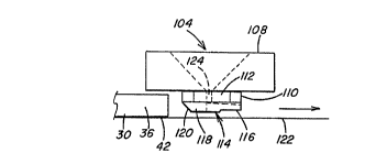
With specific reference to Figs. 6 and 7, the nozzle
104 has a base 108 supporting a raised platform 110 having a
pair of opposite flat sides 112 clearly shown in Fig. 6. The
platform 110 has a forming surface including a forming tip 114
that forms the shaped layer 38 in a manner to be discussed.
The forming tip 114 has a generally arrow shaped end 116
narrower than opposite end 118. The end 116 is lower in height
than the end 118 with the end 118 sloping toward the platform
110 as shown by numeral 120 in Fig. 7. In practice the U-
shaped spacer 30 advances from left to right as shown in Fig.
7. As the lead end of the spacer 30 engages the tip 114 the
sloped end 120 biases the leading end of the spacer downward
as viewed in Fig. 7 against conveyor 122 in those instances
where the lead end of the spacer is raised. As the spacer
advances past the nozzle 104 the adhesive is extruded through
holes 124 and 126 onto the base of the spacer as the forming
tip 124 shapes the adhesive to provide the shaped layer 38 on
the base of the spacer.
In making the unit discussed above, the base 108 had
an outside diameter of about 2-1/2 inches (6.35 cm) and a
thickness of about 1/4 inch (0.635 cm). The platform 110 had a
CA 02208277 2000-02-08
~. . , s
-21-
height of about 3/8 inch (0.95 cm). The platform was circular
with a diameter of about 0.52 inch (1.37 cm) except for the
flat sides 112 that are spaced from each other about 0.485
inches (1.23 cm) and each have a length of about 0.23 inch
(0.53 cm). The tip 114 at the narrow end 116 has a width of
about 0.028 inch (0.020 cm) and expands toward the center line
of the tip to a width of about 0.062 inch (0.157 cm). The
slope surface 120 starts at the edge of the platform 110 and
terminates about 0.125 inch (0.37 cm) therefrom. With
reference to Fig. 7, the tip 114 at the sloped end 118 has a
height of about 0.080 inch (0.20 cm) and at the narrow end 116
of about 0.065 inch (0.165 cm). The holes 124 in the platform
each had a diameter of about 0.120 inch (0.3 cm) and the hole
126 in the tip had a diameter of about 0.093 inch (0.236 cm).
In practice, H. B. Fuller adhesive HL-5102-X-125
having a desiccant therein is heated to about 250°F (482°C). As
the U-shaped spacer 30 moves past the nozzle 104, the platform
110 is positioned between the outer legs 34 and 36 of the
spacer with the highest portion of the tip 114 e.g. end 118 of
the tip spaced about 1/32 inch (0.08 cm) from the base 42 of
the spacer 36. As.the spacer 30 moves past the nozzle the
sloped end 120 urges the leading edge of the spacer downward,
if lifted, toward the conveyor as adhesive is extruded from
the holes 124 and 126 to provide the shaped layer 38.
The narrow portion of the tip and the step of the
tip prevent tailing of the adhesive when the flowing e.g.
pumping or extrusion of the material is stopped. It is
expected that providing a step for the platform 110 similar to
that of the tip will further ensure elimination of tailing.
With reference to Figs. 8 and 9, there is shown
nozzle 130 having platform 132. The nozzle 130 is similar
to the nozzle 104 except the platform 132 is provided with a
lower portion 134 and a raised portion 136 and the
CA 02208277 2000-02-08
.~ r
-22-
platform and nozzle where the change in elevation occurs is
radiused surface 140 as shown in Fig. 8. It is expected that
the radiused surfaces 140 and change in elevation will
eliminate tailing.
The term "tailing" as used herein is the noted
effect that occurs when the flowing e.g. pumping or extrusion
of the material is stopped but due to the adhesive adhering to
the nozzle, strings of adhesive are pulled.
In the instance where an insulating unit e.g. the
unit 20 shown in Figs. 1 and 2 has an insulating gas between
adjacent glass sheets 22, 26 and 26, 24, the insulating gas
may be flowed into the compartment between the glass sheets in
any convenient manner. For example and with reference to Figs.
and 11 there is shown injector arrangement 150 that may be
used to move an insulating gas into a compartment while
removing air in the compartment through a single spacer hole.
The injector arrangement 150 includes a spring biased
bifurated member 152 having outer legs 154 and 156 connected
to a base 158. The spring member 152 is made of spring metal
such that the legs 154 and 156 are spring biased toward one
another to engage the glazing unit in a manner discussed
below. The member 152 used was a binder clip.
An inner tube 160 has an enlarged end 162 mounted
in a housing 164 and passes through the housing. The tube
160 extends-beyond the housing and outer tube 166 and is
shown in Fig. 11 as end 168. The end 168 of the tube 160 is
sized for insertion through the base 42 of the spacer 30
(see Fig. 2). The housing 164 has a hole 170 that provides
access to the hollow interior of the housing. The outer
tube 166 has end connected to the housing 164 and has
external threads thereon. The housing arrangement is
secured to the base 158 of the member 152 by passing the
outer tube through a hole (not shown) in the base 158. A
CA 02208277 2000-02-08
4. ~
-23-
nut 172 threaded on the outer tube 166 engages O rings 174 on
each side of the base 158 about the tube 166 to capture the
base between the housing 164, the O rings 174 and the nuts 172
as shown in Fig. 11.
In practice the end 162 of the inner tube 160 is
connected to an Argon supply (not shown), and the injector
arrangement clamped to the unit by spreading the legs 154 and
156 apart by urging members 180 and 182 toward one another and
inserting the end 168 of the inner tube 160 in a hole (not
shown) in the spacer e.g. aligned holes in the substrate 70.
The members 180 and 182 are released to clamp the nozzle
arrangement 152 on the edge of a unit as shown in Fig. 12. It
is recommended that the clamp engage the glass at the edge
assembly of the unit e.g. edge assembly 28 of the unit 20
shown iri Fig. 2, to prevent damage to the glass. As Argon
moves into the unit through the inner tube 168, air in the
compartment between the sheets is displaced and moves out of
the compartment through the annulus between the outer tube 166
and the inner tube 160 through the housing 164 and out of the
hole 170. After the compartment is filled with Argon the
nozzle is removed and the hole sealed in any convenient manner
e.g. with a sealant or a closed end rivet.
When the unit has one chamber e.g. as taught in the
EP Application, one nozzle centrally located as shown in Fig.
12 is preferred. When the unit has two or more compartments
e.g. unit 20 shown in Fig. 2, one nozzle-may be used for each '
compartment or a nozzle arrangement having two nozzles may be
used e.g. nozzle arrangement 194 shown in Fig. 13. i
As can now be appreciated the invention is not j
limited to making a triple glazed unit. For example as shown
in Fig. 14 there is a unit 200 having four glass sheets 22, 24
and 202. When more than three sheets are used, a blank or
spacer 204 may be used between glass sheets 202 shown in Fig.
14. Further, the intermediate sheet may have a hole drilled
therein to interconnect the compartments of the triple glazed
unit.