Note: Descriptions are shown in the official language in which they were submitted.
CA 02208381 1997-06-20
CWC- 128
APPARATUS FOR CUTTING AND THREADING
A TAIL OF A TRAVELLING WEB IN A PAPERMAKING MACHINE
Field of the Invention
The present invention relates to an apparatus for cutting and threading
a tail from one section of a papermaking machine to a downstream section.
In particular the present invention relates to the use of a waterjet cutting
s device to clip or chop the tail traveling through a calender or pull stack.
Background of the Invention
In practice, after a paper break, the web is threaded in stages through
the paperm~king machine by cutting a tail and threading the tail through the
machine. Any part of this threading process that can be automated is
10 advantageous because it reduces downtime associated with web breakage.
The term tail refers to an edge piece cut into the traveling web by means of
a cut into the web from the edge of the web and a continuous slit along the
web which forms the "tail" or "edge piece" of the paper web. This tail may
be blown or directed into the next portion of the paper making machine at
which time the remainder of the web is severed widening the tail, so that the
CA 02208381 1997-06-20
- 2 - cwC - 128
tail pulls the web through the next portion of the machine to be threaded.
Typically the tail is anywhere from 10 to 20 centimeters in thickness
compared to the remainder of the width of the web which can be in the
order of 7 meters.
In the calendering section of a paper machine, a leader, or tail is cut
upstream of the calender anywhere from 10-20 centimeters in width and
threaded through the calender stack into nips formed by two-, or several
successive rolls of the calender, at which point it emerges from a last nip
formed by an upper "queen roll" and a lower "king roll". As the tail passes
through the last nip, the tail follows the king roll and is removed from the
king roll by a doctor blade that directs the paper web into a broke pit. Once
the tail is threaded through the last nip in the calender, the tail cutter
upstream of the calender widens the web to full web width which can be in
the order of 7-10 meters.
It is at this stage that the tail cutter upstream of the calender is cutting
a new slit into the web which now follows through all nips and emerges at
the king roll as a fresh tail. This new tail must be severed, or "chopped" in
its cross width for thre~cling into the next section of the papermaking
machine such as a reel, winder, coater, or possibly a dryer section.
While the use of waterjet cutting devices to cut a tail in a
papermaking machine has been disclosed in U.S. patent 4,931,140 issued
June 5, 1990 to Peltola et al, this patent is primarily concerned with moving
the water jet back and forth at a suitable rate to reduce wetting of the web
supporting felt. There is no teaching associated with how to use such a
CA 02208381 1997-06-20
- 3 - cwc - 128
waterjet cutting device in association with tail cutting in a calender section
of a paperm~king machine where the web passes or travels over rolls in the
papermaking machine and must be removed from those rolls.
An automatic web threading apparatus for a calender section of a
papermaking machine is disclosed in U.S. patent 4,904,344 issued February
27, 1990 to Robert E. Peiffer. This patent teaches using a foil that moves
into engagement with the edge of the web passing over the king roll
downstream of the nip between the queen and king rolls. The doctor blade
associated with the king roll includes an air nozzle that directs air up
o towards the underside of web. The air nozzle and the foil combine to cause
the edge of the paper web to lift off the king roll. A support plate tray
carries a knife that moves the knife blade forward into contact with the edge
of the paper lifted off the king roll to cut a tail from the edge of the paper.
The knife is withdrawn and the tail travels over the support plate to the next
section of the paper making machine. While this patent discloses an
automatic tail cutter and threading apparatus, the patent requires the
movement of a foil into contact or close proximity with the web at the king
roll, an air nozzle and movement of a cutting blade into the web portion
lifted off the first or king roll.
U.S. Patent 5,622,601 issued April 22, 1997 to Adams et al discloses
a combination doctor and waterjet cutting device fixedly located relative to
each other on a platform that moves laterally of a roll to clip a tail edge and
remove the tail edge from the roll. In this arrangement both the waterjet and
doctor blade move into position with the roll. This arrangement, however,
CA 02208381 1997-06-20
- 4 - cwc - 128
does not allow for a reverse cut should a new tail need to clipped as a result
of improper thre~-ling of the clipped tail downstream.
It would be an advantage over the above discussed automatic web
threading apparatus to provide an automatic tail cutting, severing and
threading apparatus for use in a calender section of a papermaking machine
that does not require movement of apparatus, such as a foil or doctor blade,
into position to effect clipping of a tail in a web or removal of the clipped
tail since these moving parts complicate the machine and consume time to
be moved into place. The quicker the tail can be cut from the web, the less
lO paper is wasted during the threading process.
Sllmm~ry of The Invention
The present invention is directed to an apparatus for chopping a tail in
a web sheet traveling through a nip between two rolls. A waterjet is
positioned adjacent the edge of the web upstream from the nip. The
waterjet directs a jet of water through the web and against the upper roll of
two rolls. The waterjet travels relative to the edge of the web either into or
out of the web to clip a tip in the tail that continues to travel with the
remainder of the web sheet towards and through the nip. The waterjet
penetrates the web and splashes against the one roll such that the wetted
portion of the one roll compresses against the tip of the tail to carry or pull
the tail around the one roll away from the other roll. The remainder of the
non-wetted web sheet continues to follow the surface of the other roll. A
doctor blade is mounted in engagement with the upper roll in line with the
CA 02208381 1997-06-20
- 5 - cwc - 128
tail to direct the tail away from the upper roll and towards the next section
of the paperm~kin~ machine.
By using the waterjet located upstream of the web, the tail can be
quickly chopped or clipped cut and the adhesion characteristics of the water
on the one roll used to direct or draw the clipped tail over the one roll which
is different from the other roll over which the remainder of the web travels.
Further the direction of movement of the waterjet into or out of the web to
clip the tail can be reversed anytime subsequent to the first tail being
clipped to provide a second clipped tail in the event the first clipped tail is
lO improperly threaded downstream.
By mounting the doctor blade against the one roll, which is the
wetted roll, the doctor blade can be continuously maintained loaded in place
against the one roll, and does not have to be moved either against the
direction of web travel or laterally relative to the direction of web travel.
While the doctor blade can be pivoted to load the blade against the one roll,
the doctor blade is positioned away from the normal travel of the web and
hence does not have to be moved out of engagement with the one roll.
Hence, cutting and doctoring the tail against a roll different from the roll
over which the remainder of the web sheet passes results in a less movably
complex and cluttered calender section.
It should be understood that throughout the specification and claims
that when reference is made to cutting a tail it is meant to be a thin edge
slice of between lO and 20 centimeters which may continue for anywhere
from lO to 50 feet, for example.
CA 02208381 1997-06-20
- 6 - cwc - 128
In accordance with one aspect of the present invention there is
provided an apparatus for chopping a tail in a web in a calender section of a
papermaking machine and for guiding the tail downstream to a next section.
The calender section has a queen roll positioned vertically above a king roll
to form a nip therebetween through which the web passes and follows the
king roll. The improvement comprises a waterjet cutting device located
upstream of the nip for directing a waterjet towards the web and the queen
roll to chop the tail in the web leaving a main web portion The waterjet
wets the queen roll whereby the tail passes through the nip and adheres to
lO the queen roll with the main web portion continuing to follow the king roll.
A first doctor blade is located downstream of the nip adjacent the queen roll
for picking up the tail from the queen roll after the tail passes through the
mp.
While the present invention has been described in relation to the
calender section of a paperm~kin~ machine, it should be understood that the
present invention may have application in other parts of a papermaking or
board making machine. Thus in accordance with another aspect of the
present invention there is provided an apparatus for cutting a tail from a
web in a first section of a papermaking machine and for guiding the tail
downstream to a next section of the papermaking machine. The first section
has a first roll positioned relative to a second roll to form a nip therebetweenthrough which the web passes and follows the first roll. The improvement
comprises a waterjet cutting device located upstream of the nip for directing
a waterjet towards the web and the second roll to cut the tail in the web
CA 0220838l l997-06-20
-7- CWC -128
leaving a main web portion. The waterjet wets the second roll such that the
tail passes through the nip and adheres to the second roll with the main web
portion continuing to follow the first roll. The apparatus includes a doctor
blade located downstream of the nip adjacent the second roll for picking up
the tail from the second roll and guiding the tail towards the next section.
Brief Description of The Drawin~
For a better understanding of the nature and objects of the present
invention reference may be had to the accompanying diagr~ tic
drawings in which:
o Figures 1 to 3 are side views of the apparatus of the present invention showing the web threading feature in various stages; and,
Figure 4 is a view similar to Figure 3 showing an alternate
embodiment.
Detailed Description of The nrawin~
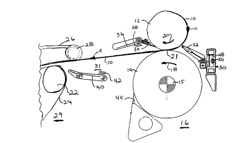
Referring to Figure 1 there is shown a paper web 10 moving in the
direction of arrow 11 through a calender section 16 of a papermaking
machine. The web 10 is shown to travel around the periphery of queen roll
12 and pass through nip 21 where queen roll 12 meets king roll 14. While
only the queen roll 12 and the king roll 14 for the calender 16 are shown in
the drawings, in practice there can be one or more stacking rolls located
above the queen roll 12 through which the web 10 winds itself in a
serpentine fashion. The king roll 14 is driven about shaft 15 causing the
king roll 14 to rotate in the direction of arrow 18 and causing the queen roll
12 to rotate in the direction of arrow 20.
CA 02208381 1997-06-20
- 8 - cwc - 128
The web 10 leaving the nip 21 of the calender section 16 is
transferred to roll 22 by being captured between one or more guide ropes 24
passing over roll 22 and the one or more guide ropes 26 passing around rope
sheave 28. This section of the papermaking machine is referred to as the
s next section 29 of the machine. The web 10 is shown to travel over an open
draw 31 between the calender section 16 and the next section 29.
Located upstream of the nip 21 is a waterjet apparatus 30 having a
waterjet nozzle 32 pointing towards the web 10 and the queen roll 12. A
first doctor blade 34 is located downstream of the nip 21 of the calender 16
o positioned adjacent to and in engagement with the queen roll 12. The
doctor blade 34 is located above and away from the normal travel 11 of web
10 through the calender section 16 and, hence, does not necessarily have to
be moved into and out of engagement with the queen roll 12. The doctor
blade 34 is followed by a first guide tray 36 against which an air shower 38
iS directed in the direction of web travel upon demand. Continuing
downstream in the direction of web travel is a second guide tray 40 also
provided with an air shower 42 which can be directed against the tray 40 in
the direction of travel of the web upon demand.
A second doctor blade 44 is located downstream of the nip 21 of the
calender 16 and positioned against the king roll 14. The function of doctor
blade 44 is explained hereafter.
The waterjet cutting device 30, first doctor 34, tray 36, and tray 40
are secured relative to an outside edge of the web 10. The mechanism these
components in place may comprise any suitable means such as, for example
CA 0220838l l997-06-20
-9- CWC -128
a base stand secured to the floor having an arm extending laterally into the
edge portion of the web 10. The waterjet cutting device or tail chopper 30
typically includes a movable carriage 48 movable along rail 50 laterally
across the width of the tail 54. The waterjet cutting device 30 can be
initially positioned adjacent the edge of the web 10 and moved laterally into
the web 10 to clip the tail. Alternatively, the waterjet cutting device 30 can
be initially positioned laterally inward from the edge of the web 10 and
moved to the outside edge of the web to chop or clip the tail. Furthermore,
this bi-directional movement capability of the waterjet cutting device 30
o allows for a second tail to be clipped anytime after a first tail is clipped by
reversing the direction of movement of the waterjet cutting device. There
may be occasion to have to quickly chop a new tail in the event the
previously chopped tail does not properly thread at some location
downstream.
Figure 1 of the drawings represents the scenario where the entire web
has been threaded through to the next section of the papermaking machine
and the web 10 is running during normal calendering operation.
Referring to Figure 2 of the drawings, there is shown the threading of
the web 10 into the calender section 16. In this scenario the web 10 has
been completely drawn through nip 21 and continues to follow king roll 14.
Doctor blade 44 extends along the king roll 14 and scrapes the web 10 from
the king roll 14. The web 10 is directed at 46 into a broke pit (not shown).
Initially, a tail is fed through nip 2 1, over king roll 1 4 and into the broke pit.
CA 02208381 1997-06-20
- 10- cwc- 128
Referring to Figure 3, the function of the tail cutting device and
threading apparatus is described. In this Figure, the queen roll 12 is shown
partially in a three dimensional perspective. The web 10 is shown for
illustrative purposes to be moving toward queen roll 12 at arrow 51. In
practice, web 10 at arrow 51 is moving toward the uppermost stacking roll
(not shown) located in the calender section 16. The web 10 at arrow 51 has
an edge slit cut about 10 to 20 centimeters in from the edge of the web 10
by means of a waterjet cutting device shown for illustrative purposes
upstream at 56. The web 10 is slit once the entire web 10 has been threaded
10 through nip 21 of the calender. The location of this waterjet 56 is upstream
from the calender section 16 and may cut against either side of web 10. The
web 10, shown passing over the top surface of queen roll 12, is divided by
the slit 53 cut out in the web 10 by waterjet 56 into a main web portion 52
and an edge portion or trim portion 54. Once the web 10, with the slit 53,
enters nip 21, or shortly thereafter, the waterjet 30 is operated to cut in, or
chop, from the edge of the web 10 across the edge portion 54 and stopping
its lateral cut at the slit 53. The waterjet 30 operating in this manner cuts a
new tail to be threaded to the next section 29 of the papermaking machine.
As the waterjet 30 cuts through the edge trim portion 54, the water jet
splashes water against the queen roll 12. As the wet portion of queen roll
12 moves past nip 21 with the wet tail portion of the edge portion 54,
adhesion occurs between the tail, or tip of the cut edge portion 54 and the
queen roll 12. The tip of edge portion 54 then follows the surface of the
queen roll 12 and is removed from the surface of queen roll 12 by doctor
CA 0220838l l997-06-20
-11- C W C -128
blade 34. Air shower 38 directs the tip edge portion 54 against tray 36 and
the tip 54 continues in the direction of arrow 58 onto the lower tray 40. Air
spray 42 directs the tip of edge portion 54 over the upwardly sloped end of
lower tray 40 between ropes 24 and 26 as shown at contact point 60 in
Figure 3. Once the tail is caught between ropes 24 and 26 at 60, these ropes
can be accelerated temporarily to straighten the edge portion 54 between the
nip 21 and the point of contact 60 similar to that shown for web 10 in Figure
1.
The main portion 52 of web 10 passing through nip 21 continues to
follow the outside peripheral surface of king roll 14 and is scraped from
king roll 14 by doctor blade 44 with the broke 46 entering the broke pit.
The main portion 52 of the web 10 continues to follow the king roll even if
a corner of the main portion 52 is wet because the main portion may extend
for several feet which will pull any wet part of main portion 52 down into
the broke pit.
Once the tail has been threaded and straightened from nip 21 to
contact point 60 in the next section 29, then waterjet 56 moves laterally
across web 10 widening the tail 54. As the tail or edge strip 54 widens, it is
pulled through the next section 29 of the papermaking machine until the
entire web 10 has been threaded into this next section 29 at point 60.
Referring to Figure 4, alternate embodiments are shown. One
alternative embodiment is to have web 10 entering nip 21 move in the
direction of lead in arrow 62 which is angled away from the peripheral
surface of queen roll 12. That is to say the web 10 does not wrap itself
CA 02208381 1997-06-20
- 12 - cwc - 128
around the peripheral surface of queen roll 12. In this alternative
embodiment, the web entering the nip 21 has already been slit upstream by
another cutter (not shown). The waterjet 30 in this embodiment acts in the
same manner as described for Figure 3 which is to chop the tail tip and to
s wet the queen roll 12.
In a second alternative embodiment, the waterjet 30 acts to cut the tail
end tip portion and maintain the slit. This might require two nozzles co-
operating to cut the edge strip and also slit the web 10. This will wet the
queen roll and once the tail 54 initially is threaded into contact point 60 of
o the next section 29, the waterjet cuts laterally across the main portion 52 of
the web severing the web 10 and at the same time increasing the width of
the tail or edge portion 54. It should be understood that the function of the
waterjet cutting device 30 in this embodiment is not limited to cutting the
web 10 angled away from the queen roll 12 as shown in Figure 4 but rather
can be used with the web 10 passing over the periphery surface of the queen
roll 12 as illustrated in Figure 3.
It should be understood that the width of the doctor blade 34 and
trays 36 and 40 are chosen to be slightly wider than the width of the edge
trim portion 54 slit in the web 10. Further, the doctor blade 34, and the
trays 36 and 40 can be angled to keep the tail 54 directed to the outside edge
of the web 10. The doctor blade 34 is shown in the drawings loaded in
place against the queen roll 12. The doctor may be pivoted about point 64
by an air cylinder (not shown) into the loaded position or away from the
CA 02208381 1997-06-20
- 1 3 - CWC - 1 28
queen roll 12 in an unloaded position. There is no lateral movement of the
doctor blade 34 in from the outside edge of the calender.
While reference is made in the disclosure to a waterjet tail cutter
located upstream of the calender section 16 for the purposes of slitting the
web 10 and cutting a tail in the web 10 prior to entering the calender section
16, any other suitable cutting tool may be used for this purpose, such as, for
example, a knife cutter.