Note: Descriptions are shown in the official language in which they were submitted.
CA 02208401 1997-06-20 9 5 l 0 0 1
~-CT1~~~ 3 4
~ 5 JAN19y6
1
BUILDING PANELS
FIELD OF THE INVENTION
This invention relates to a method and apparatus employed in building
construction,
and in particular a form of panel employing the principle of post and beam
construction and the method of building using these panels.
BACKGROUND TO THE INVENTION
The cost of timber in building construction can be expensive, and methods of
construction employing concrete can require substantial amounts of equipment
for
bracing and supporting wet concrete during construction.
OBJECTS OF THE INVENTION
Thus, it is an object of the present invention to provide an apparatus and
method
which allows building construction employing a concrete post and beam
construction, which overcomes at least some of the abovementioned problems, or
which at least provides the public with a useful alternative.
Other objects of the invention will become apparent from the following
description,
which is given by way of example only.
BRIEF DESCRIPTION OF INVENTION
According to one aspect of the present invention, there is provided a building
panel
having an upper edge which is adapted to interlock with a lower edge of a
vertically
adjacent substantially identical panel, the panel having side edges which are
substantially planar to permit abutment of a side edge of one panel against a
side
edge of an horizontally adjacent substantially identical panel, and wherein a
continuous channel extends the length of each side edge and the upper edge.
- F "-'~'="vx 'sriv s ni: ea aaox .
i4D6J1.~91Mt'!81
~
SUBSTITUTE SHEET =. "' '~.'T'' 0A-'G1.~SAn G'N
CA 02208401 1997-06-20
:= ~~i~~Z
9 5 / 0 0 1 3 4
1 5 JAN i5 6
2
The panel can either be a square or a rectangle. The continuous channel can be
formed substantially mid-way between a front face of the panel and a back face
of
the panel.
In one preferred form of the building panel of the present invention, the
depth of the
continuous channel on each side edge is between 5% and 10% of the width of the
panel.
In a further preferred form of the invention, the depth of the continuous
channel in
the upper edge is between 10% and 15% of the height of the panel.
Preferably the building pahel of this invention is made of a durable,
lightweight
material, for example polystyrene.
In a preferred form of the invention the building panel can further comprise a
diagonal channel interconnecting one end of the continuous channel at a lower
part
of a side edge with the continuous channel substantially at one end of the
upper
edge, diagonally opposite the lower part of a side edge.
In a further aspect of the present invention, there is provided a wall
incorporating a
post and beam construction formed using multiple building panels, wherein each
panel has a continuous channel extending the length of each side edge and an
upper edge, and wherein the continuous channel of each building panel
interconnects with the continuous channel of each adjoining panel in the wall,
the
channels filled with concrete forming the post and beam construction.
SUBSTITUTE SHEET
CA 02208401 1997-06-20
CUNZ 95100 134
1 5 JAN 1996
3
The panel can either be a square or a rectangle. The continuous channel can be
formed substantially mid-way between a front face of the panel and a back face
of
the panel.
In a further aspect of the present invention, there is provided a method of
building
construction employing building panels, upper edges of which are adapted to
interlock with lower edges of vertically adjacent substantially identical
panels, and
side edges of which are substantially planar to permit abutment of a side edge
of
one panel against the side edge of an adjacent panel, and wherein a continuous
channel extends the length of each side edge and the upper edge, the method
comprising:
t = -
a) positioning a first layer of abutting panels, wherein the continuous
channel in a side edge of one panel is adjacent the continuous
channel of a side edge of an adjacent panel forming a post
channel, and the continuous channel in the upper edge of each
adjacent panel forms a beam channel;
b) pouring wet concrete into the post channels and beam channel of
the first layer of panels;
c) positioning a further layer of panels vertically above and aligned
with the first layer of panels so that the continuous channels in
the side edges of the panels of the further layer form post
channels which continue vertically above the post channels of the
first layer;
d) pouring wet concrete into the post channels and a beam channel
formed in the upper edge of the further layer of panels; and
e) repeating steps c) and d) to produce a wall of the required height.
SUBSTITUTE SHEET
CA 02208401 1997-06-20
:~7,
9 5/ 0 0 13 4
1 5 JAPd 1996
4
In a preferred form of this aspect of the invention reinforcing rods can be
positioned in the post and beam channels during construction.
In a further preferred form of this aspect of the invention, each building
panel can
further comprise a diagonal channel interconnecting one end of the continuous
channel at a lower part of a side edge and a mid-portion of the continuous
channel substantially at one end of the upper edge, diagonally opposite the
lower
part of the side edge, these diagonal channels forming additional
strengthening to
the walls formed by the method. Preferably, the building panels in each layer
of
the wall are positioned so that each adjacent panel has the diagonal channel
running in an opposite direction.
The panel can either be a square or a rectangle. The continuous channel can be
formed substantially mid-way between a front face of the panel and a back face
of the panel.
BRIEF DESCRIPTION OF DRAWINGS
Other aspects of the present invention will become apparent from the following
description which is given by way of example only, and with reference to the
accompanying drawings, in which:
Figure 1: shows a perspective view of a building panel according
to one aspect of the present invention.
Figure 2: shows a cross-section through the middle of a building
panel of figure 1.
c_;LRBSTiTUTE SHEET
CA 02208401 1997-06-20
~c-., ~:;,- T 95 /00 134
1 5 JAN 1996
Figure 3: shows edges of a panel of figure 1 from views A, B, C
and D.
Figure 4: shows a side view of adjoining building panels of the
present invention in a wall construction.
Figure 5: shows a view from above of two panels of figure 1
adjoined in a wall construction.
Figure 6: shows a cross-section through a central part of two
panels adjoined vertically in a wall construction.
.
Figure 7: shows a vertical cross-section through a lower part of a
building panel of figure 1 adjoining a floor or foundation of a building
structure.
Figure 8: shows a view from above of a corner of a building
construction incorporating building panels of the present invention.
Figure 9: shows a view from above of an internal wall
intersection incorporating building panels of the present invention.
Figure 10: shows a vertical cross-section through a building panel
of the present invention adjoining a roof framing construction.
Figure 11: shows a vertical cross-section through a building panel
of the present invention adjoining an alternative roof framing
construction.
SUBSTITUTE SHEET
CA 02208401 1997-06-20 9 5 0 0 1 3 4
1 5 JAN 1996
6
DETAILED DESCRIPTION OF DRAWINGS
According to a preferred form of the apparatus of the present invention, as
shown in figures 1 to 3, there is provided a building panel 1, preferably made
of
polystyrene. The panel 1 is about 1.2 m2 in the preferred embodiment.
However, it will be appreciated that different circumstances may require
panels
of different sizes, and the scope of the invention is not limited to panels of
any
particular dimensions.
The front 2 and back 3 surfaces are essentially flat. The upper edge 4 has
recessed edges 5 which may form a tongue and groove connection with a
bottom edge 6 of another panel, the bottom edge 6 having a recessed portion 7.
Side edges 8, 9 are flat, to enable adjacent panels to abut forming
substaritially
flush front and back surfaces.
The top edge 4 includes a central upper channel 10, whilst side channels 11
are
formed in the central part of side edges 8, 9. The upper 10 and side 11
channels
each has a width substantially 50% of the thickness of the building panel 1.
Referring to figure 2, the depth "a" of upper channel 10 is at least 10%, and
up
to 15%, of the height "b" of a building panel 1. The depth "c" of each side
channel 11 is between 5% and 10% of the width "d" of the panel 1.
A diagonal channel 12 passes through the centre 13 of the panel 1 from the
upper channel 10 to a lower part 14 of a side channel 11. This diagonal
channel
12 is an optional feature where additional strengthening is required.
The method of construction of the present invention, employing the building
panels of the invention, is now described.
SUESTtTUTE SHEET.
CA 02208401 1997-06-20
9 5 i 0 0 1 3 4
1 5 JAN 1996
7
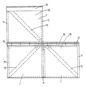
A wall is constructed employing one layer of building panels at a time.
Referring
to figure 7, a panel 1 of a lower layer 15 of panels is positioned on a
preformed
base 16. Reinforcing rods 21 may be employed if necessary. A series of panels
1 are positioned on this preformed base 16 side edge 8 to side surface 9., as
shown in figures 4 and 5. Adjoining panels are kept aligned using battens 17
tied together by wire 18 passing through the join 19 between the adjacent
panels, as shown in figure 5.
With the lower layer 15 of panels in position concrete is poured into the
upper
channel 10 to fill this channel 10 as well as side channels 11 and diagonal
channels 12 in each panel 1. Vertically disposed reinforcing rods 20 can be
positioned in side channels 11, and horizontally disposed reinforcing rods 21
can
be positioned in upper channel 10, as shown in figure 5.
Reinforcing rods can be constructed from timber, steel and the like.
The panels 1 of the lower layer 15 are positioned so that the diagonal channel
12
of each alternate panel runs in the opposite direction, as shown in figure 4.
With the lower layer 15 completed a second layer 22 of panels 1 is positioned
on
top of the lower layer. Referring to figures 4 and 6, the recessed slot 7 of
the
bottom edges 6 of the second layer 22 form a tongue and groove connection
with the recessed edges 5 of the top edges 4 of the lower layer 15. The panels
of the second layer 22 are aligned directly above the panels of the lower
layer 15
so that the side channels 11 continue in a substantially vertical post-form.
However, as can be seen in figure 4, each of the panels of the second layer 22
is
inverted in relation to the adjacent panel of the first layer 15 so that the
diagonal
channels 12 form continuous lines between layers of panels.
SUBSTITUTE SHEET
= CA 02208401 1997-06-20
9 5 /00 134
1 5 JAN1996
8
Once the new layer of panels is in position more concrete is poured to fill
the
upper, side and diagonal channels 10, 11, 12 of the new layer.
This process of construction is repeated, as necessary, to complete the wall
structure to the required height.
Outer corners are constructed as shown in figure 8. One panel 24 is positioned
perpendicular to a second panel 25 so that the side edge 8 of panel 25 is
substantially aligned with the inner surface 26 of side channel 11 of panel
24.
Battens 27, held in place by wires 28 passing through the panels 24, 25 are
used
to hold the panels 24, 25 in position and form the outer corner 29. The corner
post area 30 is therefore filled with concrete at the same time as the
channels of
the relevant layer of panels. Reinforcing rods may be positioned vertically 31
in
the corner post area 30 and horizontally 32 from the upper channel 10 of panel
24, through the corner post area 30 to the upper channel 10 of panel 25.
The construction of wall intersections is shown in figure 9. A substantially
vertical segment the thickness of a panel is cut in the front 2 or back 3
surface
of a panel 34 of the main wall of panels 35 to the depth of the inner surface
36
of the upper channel 10. An end 37 of an intersecting panel 38 is slotted into
this segment. The side channel 11 of intersecting panel 38 intercepts with the
upper channel 10 of panel 34. Vertically 31 and horizontally 32 disposed
reinforcing rods may be incorporated.
Roof framing may be affixed to the top layer 40 of panels of a wall
construction
as shown in figures 10 and 11. In figure 10 a galvanised plate "T" bracket 41
is
f
affixed in side channels 11 between adjacent panels. This plate "T" bracket 41
is joined to reinforcing rod 42. A joist hanger 43 is affixed on the
protruding part
Si~~ST6 T UTE SHEET
CA 02208401 1997-06-20
95 /00 ~34
1 6 JAN 1996
9
44 of the plate "T" bracket 41, which is in turn affixed to lintel 45 by coat
screw
46.
Alternatively, as shown in figure 11, reinforced top channel 47 of the top
layer
40 of panels forms the support for pitching plate 48 secured via threaded
extensions of vertically disposed reinforcing rods 49. Gang nail truss 50 is
supported on pitching plate 48.
The exterior finish of a wall constructed employing building panels of the
present
invention can be of plaster or other finish, and the interior may optionally
include
a gib-board finish.
Using the method and apparatus of the present invention multistorey
constructions can be built, up to three storeys high.
Thus, employing the building panels of the apparatus of the present invention,
the method of the present invention enables the building of walls
incorporating a
post and beam construction, and this method is adapted to allow internal and
external wall connections and roof connections. The method requires no
substantial formwork during construction, thus saving building costs.
Although the invention has been described by way of example, and with
particular reference to the preferred embodiments shown in the accompanying
drawings, it should be appreciated that variations and modifications may be
made
thereto, without departing from the scope of the invention as herein
described.
For example, the building panels described are made of polystyrene, but other
durable, lightweight materials could also be used. Further, the concrete
structures formed in the upper channels and side channels provide horizontal
and
~UBSTi -I UTE SHEET
CA 02208401 1997-06-20
9 5/ 0 013 4
JAN 1996
vertical bracing respectively, of a wall of panels. Diagonal bracing is an
optional
addition. It is also envisaged that diagonal bracing could be provided in both
directions by each panel having a diagonal cross configuration of internal
channels.
SUBSTITUTE SHEET