Note: Descriptions are shown in the official language in which they were submitted.
__
r
EAT 0165 PEP
CA 02208487 1997-06-13 95-ELT-720
SYSTEM AND METHOD FOR PREVENTING GEAR
HOPOUT IN A COMPOUND TRANSMISSION
Technical Field
The present invention relates to compound
vehicle transmissions, and more particularly to a system
for preventing gear hopout during "power take off" (PTO)
operation in a compound transmission.
Background Art
Compound change gear transmissions are typi-
tally associated with heavy duty vehicles such as large
trucks, tractor/semi-trailers, and the like. Compound
transmissions comprise main and auxiliary transmission
sections connected in series, and provide a total number
of available transmission ratios equal to the product of
the main and auxiliary section ratios. By way of
example, a compound change ge-ar transmission comprising
a four (4) speed main section connected in series with
a four (4) speed auxiliary section will provide sixteen
(4x4=16) available ratios.
Power is transmitted from the engine, through
the master clutch and into the transmission via the
input shaft. In "Fuller" transmissions, a gear is
splined to the input shaft (namely the headset gear)
which is permanently enmeshed with two countershaft
gears situated 180° apart on the periphery of the
headset gear. Torque is transmitted to the countershaft
gears and subsequently through the countershafts. The
countershafts generally include a number of gears which
. CA 02208487 1997-06-13
i
EAT 0165 PEP -2-
mate with mainshaft gears which are placed along the
same axis of the input shaft, free to float on a float-
ing mainshaft. Clutches are provided between the
mainshaft and the mainshaft gears to provide progressive
ratios. By moving a clutch from its neutral position to
an engaged position, torque is transmitted from the
countershafts, into the mainshaft gear, through the
clutch and into the mainshaft. This method splits the
input torque equally between the countershafts and
brings the geared torque back into the mainshaft gear,
again split equally.
For the torque to be split equally and effec-
tively, it is important that the mainshaft, mainshaft
gears, and clutches are able to float to assume centered
positions. It is not necessary to firmly fix the
mainshaft gears and mainshaft, as is common practice
with single layshaft transmissions, since the separating
and tangential forces generated at the gear teeth are
equal and opposite and therefore cancel each other out.
In fact, fixing the mainshaft/input shaft gears can be
detrimental and produce a torque imbalance because it is
impossible to manufacture the geartrain perfectly, i.e.,
to absolute sizes without tolerance. The manufactured
tolerances can result in the gear teeth of the mainshaft
and input shaft gears being more heavily loaded on one
side than the other, and consequently, the gears on one
countershaft are loaded more than on the other. Fur
thermore, this can give rise to gear tipping problems
and, in extreme cases, gear hopout during normal driving
conditions.
In a single layshaft, medium-duty transmis-
sion, torque is supplied into the transmission via the
' CA 02208487 1997-06-13
. 3 L
EAT 0165 PEP -3-
input shaft through the headset gear, and is passed from
the headset gear to a mating layshaft gear, and into the
single layshaft. In this case, the mainshaft is simply
supported with bearings with very little radial clear-
s ante. The mainshaft gears are held concentric with the
mainshaft on needle roller bearings. This is necessary
due to the high tangential and separating forces set up
between the two mating gears which must be reacted
through rolling elements into the transmission housing.
Compound transmissions are sometimes used for
"power take off" (PTO) operation in which torque is
transmitted from one of the countershafts to an ancil-
lary unit, such as a pump or flange device for operating
a truck bed lifter, etc. The headset gear of a conven-
tional Fuller twin countershaft transmission is splined
to the input shaft with a small diametral float, and
when a PTO is fitted to the drive from the front coun-
tershaft, the transmission is utilized in a single
layshaft manner. The headset gear or mainshaft gears
are not coupled to the mainshaft, hence no torque split.
The headset gear drives torque through one countershaft
only. Since the headset gear is not coupled with the
clutch, there cannot be any gear hopout. The small
diametral clearance ensures that the headset gear runs
concentric with the input shaft and the large drive
splines are strong enough to sustain the load cycles
during PTO operation.
In certain designs, the splitter is configured
such that the headset gear, which is usually mounted on
the input shaft via a spline, can be free to rotate and
float, and performs the low split function (on an
overdrive transmission) as well as the fourth gear
' CA 02208487 1997-06-13
EAT 0165 PEP -4-
function. This gear is mounted on a spindle which is
screwed into the mainshaft. The headset gear bore
includes a clearance fit to the spindle so that it may
float under normal driving operation to ensure ~a bal-
anced torque split. It is also supported axially by
cylindrical thrust roller bearings which compensate for
the axial thrust forces apparent during normal operation
due to the helical gearing, which is not balanced.
These forces are accompanied by a differential rotation
between the headset gear and spindle when the low split
gear is selected (i.e., when it is a driving gear),
hence the need for thrust bearings. A splitter gear is
then placed on the input shaft, forward of~the head-
set/fourth gear with a plain clearance bore to the input
shaft which provides a high split function. These two
gears are then selectable using a splitter clutch
splined to the input shaft and free to slide along the
spline to supply the clutching function.
This design is operational for normal driving
conditions, however, when these two gears are used for
PTO operation, there is a tendency for the clutch to
hopout of engagement. In essence, the reason for this
hopout condition, both at high and low split, is due to
the fact that the transmission is being used as a single
layshaft transmission without bearings under the driving
gear.
The hopout can be attributed to inadequate
parallelism and concentricity between the selected
splitter or headset gear, splitter clutch and shaft on
which the gear is situated. The gear becomes displaced
radially taking up the clearance between the gear bore
and shaft at the high split position, and similarly at
CA 02208487 1997-09-30
EAT 0165 PEP -5-
the low split position but with the added clearance that
exists due to the floating nature of the mainshaft and
spindle. This results in a tipping affect.
The need exists for providing such torque
splitting options, while also providing the availability
of PTO operation corresponding with both the splitter
gear and the headset/fourth gear. It is necessary to
provide gear float for balanced torque splitting,
however, unfortunately, this float allows greater gear
tipping, particularly during PTO operation, which
increases the likelihood of gear hopout at the splitter
clutch.
It is desirable to provide a compound trans-
mission design which provides substantially balanced
torque splitting, with the availability of PTO operation
corresponding with both the. splitter gear and head-
set/fourth gear without increasing the risk of gear
hopout during PTO operation.
Disclosure Of The Invention
The present invention overcomes the above-
referenced shortcomings of prior art compound
transmission assemblies by providing a compound
transmission which includes a splitter gear and
headset/fourth gear, both mounted on the input shaft.
The splitter gear is provided with a minimal diametral
float of between 0.005 and 0.020 inches with respect to
the input shaft in order to minimize splitter gear
tipping while allowing substantially balanced torque
splitting, and the headset/fourth gear is mounted to
the input shaft via a pair of oppositely tapered roller
bearing sets disposed about the input shaft to minimize
CA 02208487 1997-09-30
EAT 0165 PEP -6-
headset/fourth gear tipping. In this manner, gear
hopout is prevented during PTO operation, and substan-
tially balanced torque splitting is accomplished.
More specifically, the present invention
provides a compound transmission assembly with reduced
gear hopout, including an input shaft disposed along a
central axis, a floating mainshaft disposed substantial-
ly along the central axis adjacent the input shaft, an
auxiliary section adjacent the mainshaft, and at least
one countershaft parallel with and spaced from the
central axis, said countershaft being operative to
transmit input shaft torque to the mainshaft and to
facilitate PTO operation. The assembly further compris-
es a splitter gear disposed on the input shaft and
having a central bore formed therethrough with a
minimal diametral clearance of between 0.005 and 0.020
inches with respect to the input shaft to minimize gear
tipping, and a sufficient diametral clearance for load-
sharing balance. A synchronizer is disposed about the
input shaft adjacent the splitter gear and includes a
clutch spline. A pair of oppositely tapered roller
bearing sets are disposed about the input shaft
adjacent the synchronizer. A headset gear is rotatably
mounted on the pair of oppositely tapered roller
bearing sets for minimizing gear tipping during PTO
operation. The synchronizer clutch spline is
selectively engageable with one of the splitter gear
and the headset gear, and the likelihood of gear hopout
of either gear with respect to the clutch spline during
PTO operation is reduced.
A method of eliminating gear hopout during PTO
operation in a compound transmission assembly is also
provided. The method comprises: (1) providing a
.' . CA 02208487 1997-06-13
EAT 0165 PEP -7-
splitter gear on the input shaft'with a minimal dia-
metral clearance with respect to the input shaft to
minimize splitter gear tipping; (2) providing a pair of
oppositely tapered roller bearing sets on the input
shaft; and (3) mounting a headset gear on the pair of
oppositely tapered roller bearing sets to minimize
headset gear tipping.
Accordingly, an object of the present inven-
tion is to provide a compound transmission assembly with
substantially balanced torque splitting capability with
low split and high split operations available while
reducing the likelihood of gear hopout during PTO
operation.
The above object and other objects, features,
and advantages of the present invention are readily
apparent from the following detailed description of the
best mode for carrying out the invention when taken in
connection with the accompanying drawings.
Brief Description Of The Drawings
FIGURE 1 shows a vertical cross-section of a
prior art "Fuller" twin countershaft compound change
transmission;
FIGURE 2 shows an enlarged partial cross
se'ctional view of a compound transmission assembly in
accordance with the present invention;
FIGURE 3 shows an enlarged sectional view of
the transmission shown in Figure 2;
CA 02208487 1997-06-13
EAT 0165 PEP =8-
FIGURE 4 shows a cut-away sectional view of a
washer and headset gear in accordance with the embodi-
ment shown in Figure 2;
FIGURE 5 shows an enlarged partially cut-away
sectional view of a washer, headset gear, and attachment
screw in accordance with the embodiment shown in Figure
2;
FIGURE 6 shows an enlarged partially cut-away
sectional view of a washer, headset gear, and attachment
screw in accordance with the embodiment shown in Figure
2; and
FIGURE 7 shows a cut-away sectional plan view
of the assembly shown in Figure 6.
Detailed Description of the Preferred Embodiment
Figure 1 shows a sectional view of a prior art
"Fuller" twin countershaft compound change transmission
assembly 10. This typical twin countershaft assembly
includes an input shaft 12 which carries torque from the
engine into the transmission. The input shaft 12 drives
the headset gear 14, which is splined to the input shaft
12, and also permanently enmeshed with opposing counter-
shaft gears 16. The countershaft 18 includes a series
of gears 20, 22, 24, 26 and 28 which mate with corre-
sponding mainshaft,gears 21, 23, 25, 27 and 29 which are
placed along the same axis as the input shaft, free to
float on a floating mainshaft 30. Clutches are provided
between the mainshaft 30 and the mainshaft gears to
provide progressive ratios. Torque then is transmitted
from the mainshaft through the auxiliary drive gear 32,
CA 02208487 1997-09-30
EAT 0165 PEP -9-
and into the auxiliary section 34, and finally through
the output shaft 36.
The present invention, as shown in Figures 2-
7, provides such a compound transmission design with
substantially balanced torque splitting, while also
providing the availability of PTO operation correspond-
ing with both the splitter gear and the headset/fourth
gear without increasing the risk of gear hopout during
PTO operation.
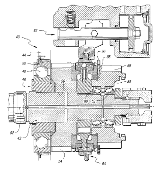
Referring to Figures 2-3, a compound change
gear transmission assembly 40 is shown in accordance
with the present invention. The assembly 40 includes an
input shaft 42 which carries torque into the assembly.
The input shaft 42 is supported within the transmission
housing 44 by a spacer 46 which is rotatably supported
with respect to the housing 44 by an input bearing 48
which is secured to a sleeve.50.
The input shaft 12 is disposed along a central
axis 52. A splitter gear 54 is disposed on the input
shaft 12 adjacent the spacer 46. The splitter gear has
a central bore 56 formed therethrough with a minimal
diametral clearance of between 0.005 and 0.020 inches
with respect to the input shaft in order to minimize
splitter gear tipping. This minimal diametral
clearance provides sufficient float in order to
maintain a substantially balanced torque split between
opposing countershafts when the splitter gear 54 is
operated in a high split mode. The diametral clearance
provides a range of approximately a 40%-60% and 60%-40%
torque split between opposing countershafts. This
differential does not create a significant balance
problem because excess torque on one countershaft is
CA 02208487 2002-11-29
'. 0 -
reacted by bearings and support restructure in the assem-
bly. In order too prevent further load-sharing or torque
split imbalance, a sufficient diametral clearance is
maintained.
Further rearward on the input shaft 42, a
headset/fourth gear 58 is mo~:r.~ec on r_he input shaf t 42
by means of a pair of oppositolv~ tapered roller bearing
sets 60,E2, which are mou.n~ed on :_~~.e input shaft. These
oppositely tapere-.i z-ollf~~_ bea~:in J Sets 60, ~2 minimi ze
headset; fourth gear 58 tippi hg.
Accordingly, the prasew.. ir_vention effectively
minimizes tipp.r_a of eit~zer the splitter gear 54 or
headset/fourth Near Cp8 when c~cera~ing in the high split
or low split P':'G mode of cpvrat~ on, respectively, ar_d
concentricity and. paral~.elis~: are maintained with
r_spect to th~_~ r:lutch. ~<~r.~v,-.:~s~concentricity and
parallelism of the. spl:~tter~ y _.._ 54 and headset/fourtr
gear 58 with respect to the ~,!'.~~..._ are maintained, these
gears are less =ikely to "hop:~ut'' ..._ engagement with the
sliding sleeve,iclutch r'8.
The splitter gear 5~-'-_ or headset/ fourth gear 58
may be selectiveiy engaged with t:he ~.nput shaft 42 by
means of the bat::lk ring ~>ynch~on?:~er assembly 64. '"his
type of baulJt rin.~ sy~~~chronizer 64 ~s fu:lly described in
U.S. Patent Na. 5,42r~,437 t~.~ ~atcr_ ~2orporation.
riltrlc:ugh this synchronizer
is preferred, other synchronize=r designs would be
compatible with the present in.ve~:a:i.on.
The synchronizer ~~ includes a fixed hub 66
secured to the .>piinE:~s 68 of the input shaft 42. Pre-
CA 02208487 1997-06-13
EAT 0165 PEP =11-
energizer springs 70 preload the guide pins 72 and
rollers 74 against an annular groove 76 formed in the
sliding sleeve 78. The sliding sleeve 78 may be slid by
the shift fork 80 by means of the shifting assembly 82
for selectively engaging -the clutch 78 with either the
splatter gear 54 or the headset/fourth gear 58. The
splatter gear includes a synchro flange 84 splined
thereto which includes gear teeth 86 which are engage-
able with the sliding clutch 78. Similarly, the head-
set/fourth gear 58 includes a synchro flange 88 splined
thereto and including gear teeth 90 which are similarly
engageable with the sliding clutch 78. Synchro rings
92,94 are fractionally engageable with the respective
synchro flanges 84,88 in order to fractionally synchro-
nize rotational speed between the fixed hub 66 and the
splatter gear 54 or headset/fourth gear 58. The synchro
rings 92,94 also act as blockers to prevent movement of
the sliding sleeve/clutch 78 toward their respective
synchro flange 84, 88 until the respective synchro flange
84,88 is brought up to spe-ed with the fixed hub 66 to
allow engagement of the clutch 78 with the respective
synchro flange.
Sliding movement of the sliding sleeve/clutch
78 is limited in the direction of the headset/fourth
gear 58 by the washer 96 and set screw 98, as shown in
Figures 2-6. In assembly, once the sleeve 78 is in
place, the washer 96 can be pushed over the headset gear
teeth 59 and indexed until the two radial holes 100 in
the washer 96 align with the two set screws 98, which
are screwed into the set screw holes 102 formed in the
headset/fourth gear 58. In this position, the splines
104 of the washer 96 are in alignment with the gear
teeth 59 of the headset/fourth gear 58 in order to act
CA 02208487 1997-06-13
EAT 0165 PEP -12-
as a positive stop, as shown in Figure 5. In this
position, a suitable hexagon wrench can be inserted
through the radial access openings 106 formed in the
washer 96 in order to unscrew the set screw 98 until the
set screw 98 is seated in the screw seats 108 formed in
the washer 96. This configuration alleviates a problem
faced in many transmissions in which the screws have a
tendency to work themselves loose due to vibrations and
with the presence of centrifugal force, unscrew, and can
enter the meshing gear teeth and cause damage. With
this design, the set screws 98 must overcome centrifugal
force to screw themselves into the gear 58, which is
very unlikely.
While the best mode for carrying out the
invention has been described in detail, those familiar
with the art to which this invention relates will
recognize various alternative designs and embodiments
for practicing the invention within the scope of the
appended claims.