Language selection

Search

Patent 2208624 Summary

Third-party information liability

Some of the information on this Web page has been provided by external sources. The Government of Canada is not responsible for the accuracy, reliability or currency of the information supplied by external sources. Users wishing to rely upon this information should consult directly with the source of the information. Content provided by external sources is not subject to official languages, privacy and accessibility requirements.

Claims and Abstract availability

Any discrepancies in the text and image of the Claims and Abstract are due to differing posting times. Text of the Claims and Abstract are posted:

  • At the time the application is open to public inspection;
  • At the time of issue of the patent (grant).
(12) Patent Application: (11) CA 2208624
(54) English Title: A CUSTOM, INTRA-ORAL, MUSCLE-CONTRACTION REDUCTION APPARATUS
(54) French Title: APPAREIL INTRA-ORAL FAIT SUR MESURE PERMETTANT DE REDUIRE LES CONTRACTIONS MUSCULAIRES
Status: Dead
Bibliographic Data
Abstracts

English Abstract


A custom, intra-oral apparatus in two parts which prevents intense contraction of
the elevator muscles of the mandible by triggering the Jaw Opening Reflex. The upper part
of the apparatus fits over the maxillary six anterior teeth forming a smooth, flat platform,
anteriorly following the curvature of the teeth with a flat posterior border, running from
the cuspid to the cuspid across the palate. The lower part of the apparatus fits over the
four mandibular incisors and has a small dome located over the longitudinal axis of the
two central incisors at the midline.When the upper and lower teeth are brought together,
the dome of the lower part of the apparatus engages the flat platform of the upper, thus
directing the force exerted by the muscles down the long axis of the lower incisors. This
action triggers the Jaw Opening Reflex and causes the muscles to relax ( to prevent
damage to these teeth ). Intense contraction of the elevator muscles of the mandible during
the R.E.M. phase of sleep has been implicated in the complex etiology of chronicheadache, tension- type headache and migraine headache pain. This apparatus is designed
to be worn while asleep and, by preventing the intense contraction of the elevator muscles
of the mandible, considerably reduces the incidence of headaches.This two part apparatus
overcomes the shortcomings of previous known art consisting of only one part, because of
its definitive prevention of contact of the posterior teeth.


French Abstract

Appareil intra-oral en deux parties fait sur mesure qui prévient la contraction intense des muscles releveurs du mandibule en déclenchant le réflexe d'ouverture de la mâchoire. La partie supérieure de l'appareil s'ajuste sur les six dents antérieures maxillaires afin de former une plate-forme lisse et plane. Elle suit antérieurement la courbe des dents avec une bordure postérieure plane et s'étend depuis une canine jusqu'à la canine de l'autre côté du palais. La partie inférieure de l'appareil s'ajuste sur les quatre incisives mandibulaires et comprend un petit dôme sur l'axe longitudinal des deux incisives centrales dans la partie médiane. Lorsque les dents supérieures et inférieures entrent en contact, le dôme de la partie inférieure de l'appareil s'engage avec la plate-forme plane de la partie supérieure, dirigeant ainsi la force exercée par les muscles vers le bas de l'axe long des incisives inférieures. Cette action déclenche le réflexe d'ouverture de la mâchoire et a pour effet de relaxer les muscles (pour éviter que les dents ne soient endommagées). Une contraction intense des muscles releveurs du mandibule durant la phase de sommeil MOR a été liée à l'étiologie complexe des céphalées chroniques, des céphalées par tension psychique et des migraines. L'appareil est conçu pour être porté durant le sommeil et, en prévenant la contraction intense des muscles releveurs du mandibule, réduit considérablement la fréquence des maux de tête. Cet appareil en deux parties remédie aux lacunes des dispositifs antérieurs constitués de seulement une partie parce qu'il évite réellement un contact entre les dents postérieures.

Claims

Note: Claims are shown in the official language in which they were submitted.


THE EMBODIMENTS OF THE INVENTION IN WHICH AN EXCLUSIVE PROPERTY
OR PRIVILEGE IS CLAIMED ARE DEFINED AS FOLLOWS:


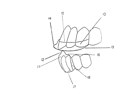
1. A custom, two piece, intra-oral apparatus which reduces muscle contraction, comprising:
an upper part which fits over, and is closely adapted to, preferably, the maxillary front six teeth
forming a smooth, flat platform whose anterior border follows the curvature of the teeth and
extends beyond their labial surfaces to a distance slightly beyond that to which the patient is able
to bring the dome of the lower part of the apparatus when fully protruding their mandible, with a
posterior border running across the palate from cuspid to cuspid;
a lower part which fits over, and is closely adapted to, usually, the lower four incisor teeth with a small
dome located on its upper surface over the longitudinal axis of the two central incisors at the
midline, in such a manner that when the upper and lower teeth are closed together, the dome
engages the flat platform of the upper part of the apparatus thus preventing any contact of the
posterior teeth, and causing the forces exerted by the elevator muscles of the mandible to be
directed down through the long axes of the lower incisor teeth.
2. An intra-oral apparatus as claimed in claim 1, wherein the actual number of maxillary teeth
covered can vary, because that is not an essential element of the invention.
3. An intra-oral apparatus as claimed in claims 1 and 2, wherein the anterior border of the upper
part of the apparatus completely covers the labial surfaces of the maxillary teeth.
4. An intra-oral apparatus as claimed in claims 1, 2 and 3, wherein the shape and placement of the
posterior border of the upper part of the apparatus can vary depending on the number of teeth
incorporated in the apparatus.


5. An intra-oral apparatus as claimed in claims 1, 2, 3 and 4, wherein the shape of the raised dome of
the lower part of the apparatus is not defined because shape is not the essential element; it is the
location and the fact that it is raised which are the essential elements.
6. An intra-oral apparatus as claimed in claims 1, 2, 3, 4 and 5, wherein the lower part of the
apparatus has flanges extending laterally from the front and/or back surfaces, following the
curvature of the arch of the teeth.
7. An intra-oral apparatus as claimed in claims 1, 2, 3, 4, 5 and 6, wherein wire extensions extend
laterally from either or both sides of the body of the lower part of the apparatus.
8. An intra-oral apparatus as claimed in claims 1, 2, 3, 4, 5, 6 and 7, wherein stainless steel wire or
orthodontic wire clasps are added on either the upper or lower or both parts of the apparatus to
aid in retention
9. An intra-oral apparatus as claimed in claims 1, 2, 3, 4, 5, 6, 7, and 8 wherein a vinyl resin is used
to construct the apparatus instead of methylmethacrylate.
10. An intra-oral apparatus as claimed in claims 1, 2, 3, 4, 5, 6, 7 and 8, wherein a light cured resin is
used to construct the apparatus instead of methylmethacrylate.
11. An intra-oral apparatus as claimed in claims 1, 2, 3, 4, 5, 6, 7 and 8, wherein a silicone material is
used to construct the apparatus instead of methylmethacrylate.
12. An intra-oral apparatus as claimed in claims 1, 2, 3, 4, 5, 6, 7 and 8, wherein the material of
construction of the apparatus is not an essential element.
13. An intra-oral apparatus as claimed in claims 1, 2, 3, 4, 5, 6, 7, 8, 9, 10, 11 and 12, wherein a soft
lining material which is actually an integral part of the apparatus is placed between the apparatus
and the teeth to act as a gasket to aid in retention.


14. An intra-oral apparatus as claimed in claims 1, 2, 3, 4, 5, 6, 7, 8, 9, 10, 11 and 12, wherein the
material of construction of the apparatus is a two part hard/soft acrylic material with the soft part
on the inside ( or fitting side) of the apparatus to aid in retention, surrounded on the outside by
the hard acrylic.
15. The method of reducing the intensity of muscle contraction of the elevator muscles of the
mandible and hence the incidence of headache pain, by means of the construction and fitting of the
custom, intra-oral apparatus described, to be worn by the patient while asleep, or at other times
considered appropriate, but not to be worn while eating.


Description

Note: Descriptions are shown in the official language in which they were submitted.


CA 02208624 1997-07-08


A CUSTOM, INTRA-ORAL, MUSCLE CONTRACTION-REDUCTION APPARATUS.

The present invention relates to chronic headaches, tension-type headaches, migraine he~d~che
pain, the pain and discomfort associated with T.M.Joint dysfunction and to the reduction ofthese
problems by prevention of severe and intense contraction of the elevator muscles of the mandible.
lo To date, the approach to treating these problems has been to treat the symptoms. Physicians will
usually take the drug approach and prescribe analgesics and/or muscle relaxants. Other approaches
include physiotherapy, cl~iroplactic, acupuncture, homeopathy, naturopathy and craniopathy.
The concept of addressing these problems by treating the cause by the prevention of the intense
contraction of the elevator muscles of the mandible is very new and the known art is very limited.
The known art consists of single devices placed on only one dental arch. Examples of these are
described in U.S. Patents # 5,085,584 and #5,513,656 dated February 4th, 1992 and May 7th, 1996 and
granted to James P. Boyd. They are either custom or semi-custom made and have several drawbacks.
They very often have to adjusted many times until the stage is reached where the posterior teeth
cannot be brought into contact in any excursion of the mandible. It is essential to the success of this
30 concept, that the posterior teeth not be able to come in contact with each other or with the appa~ s
because, if this occurs, the intense contractions of the muscles can again take place. As soon as the
posterior teeth can be clenched upon, the Jaw Opening Reflex is neutralized and its effect lost.
The design of the known art is such that a patient could move the device into a position in which
pressure could be applied to a single tooth in a direction other than down the long axis of the tooth which
40 could result in the loosening of the tooth with resultant loss of supporting bone structure.
The material with which the semi-custom devices are constructed tends to be porous, stains very
easily, is easily impregnated by oral bacteria and quickly loses its clinically clean appearance.

CA 02208624 1997-07-08


The known art is quite difficult to adapt to situations where patients have serious malocclusions
and/or deep overbites. A large antero-posterior discrepancy in the upper and lower arches (large overjet)
also presents difficulties.

The appalalus in this new invention consists oftwo completely separate parts. The first preferably
fits
over, and is very closely adapted to the maxillary ( or upper ) 6 anterior teeth ( although in difficult cases
where retention of the apparatus is a problem, the number of teeth incorporated into the appalallls can
vary). The other part fits over and is closely adapted to, usually, the 4 lower ( or mandibular ) incisor
teeth.
This invention embodies several ideas new to the known existing art and succes~fi-lly addresses
the shortcomings of the said known art.
The known existing devices have the potential to allow a clenching patient to isolate and clench
on a single tooth in a direction which could result in the loosening of the tooth and the eventual loss of
the bone supporting that tooth.

The design of this new apparatus completely precludes this possibility because of the smooth flat
platform of the upper part of the appal ~lus.
The known existing devices can have a situation where it is extremely difflcult to prevent the
lower cuspid teeth from touching the device and allow clenching and intense muscle contraction to occur.
In such cases, tooth structure will actually be removed from the tip of these teeth.

The design of this new apparatus completely precludes this possibility, without the need for any
adjustments to address this problem at future visits ( which are time cons~lming and costly to the patient ).
The requirement to remove tooth structure from healthy lower cuspid teeth is completely elimin~ted

CA 02208624 1997-07-08


any forward or lateral resistance to the lower part of the device and, because of the shape of the platforrn,
the only force which can be applied to the lower anterior teeth is along the long axis of the teeth. Teeth
can best resist forces exerted down their long axis - much more so than forces exerted in any other
direction. This one aspect of the design greatly reduces the threat to the integrity of the periodontal health
lo of the patient's teeth.


CA 02208624 1997-07-08


The invention, as exemplified by a prefel . ed embodiment, is described with reference to the
drawings in which:
Figure 1 is a view of both parts of the apparatus showing them in place on the teeth as seen from the
front of the mouth showing also how the two parts come together and prevent the posterior teeth
o from coming into contact.
Figure 2 shows both parts of the apparatus on the teeth as seen from the lateral aspect, showing how the
parts come together and prevent the posterior teeth from coming into contact.
Figure 3 is a plan view of the upper part of the apparatus in place on the teeth.
Figure 4 is a view of upper part of the apparatus shown in figure 3 shown from the front of the mouth.
20 Figure 5 is a cross-sectional view of the upper part of the apparatus in figures 3 and 4 taken through its
midline.
Figure 6 is a plan view of the lower part of the apparatus in place on the teethFigure 7 is a view of the lower part of the apparatus shown from the front of the mouth
Figure 8 is a cross-sectional view of the lower part of the apparatus taken through its midline

Referring further to the drawings, figure I shows the upper part of the apparatus (10) and the
lower part of the apparatus ( I I ) and shows how they engage each other when the teeth come together.
The dome of the lower part (12) engages the flat platform (13) of the upper part thus preventing the
posterior teeth from coming into contact.
The extension of the flat platform of the upper part beyond the labial surfaces of the upper teeth
(14) can be clearly seen, as can the extension up the labial surfaces (15)
The top surface ofthe lower part is clearly visible (16) as is its lower border (17). The main body

CA 02208624 1997-07-08


of the lower part is extended laterally to include the four lower incisors but must be kept clear of the
cuspids (18).
Figure 2 also shows how the two part of the apparatus come together with the dome of the lower
(12) eng~ging the flat platform (13) ofthe upper.This drawing also shows that, due to the shape ofthe
platform, and the position of the platform on the upper and the dome on the lower parts of the appa~ s,

no matter where the patient is able to position the mandible, the forces exerted by the muscles are always
transmitted through the long axis of each of the four lower incisors.
In figure 3 which is a plan view of the upper part of the appa~ s, the curved anterior border of
the upper part is shown ( 19) having the same curvature as the arch of the teeth. The smooth, flat platform

(13) can be seen showing the position and shape of its posterior border (20). The forward extension of
the flat platform beyond the labial surface of the upper teeth ( 14) is much easier to see and understand in
this view.This forward extension of the platform is extremely important to the success of the appa~ s
and is determined by the patients ability to protrude the mandible and is custom made to that criterion.
In figure 4 the curved anterior border of the upper part is shown ( 19) as is the extension of the flat

platform beyond the labial surfaces of the teeth (14).
In figure 5, the posterior border of the upper part of the apparatus (20) is clearly indicated as is
the smooth, flat platform (13). The significance ofthis platform can be seen in this view as it elimin~tes
the irregularities presented by the shapes of the teeth which could provide resistance to the lower part of
the apparatus hence allowing the forces exerted by the muscles to be directed against an individual tooth.

The flat platform çlimin~tes this possibility altogether. The extension of the platform beyond the labial
surface ofthe teeth is shown (14) and its extension up the labial surface ofthe teeth is also indicated (15).
Figure 6 shows the anterior border of the lower device and its curvature to conform to the lower

CA 02208624 1997-07-08


teeth (21). The top surface (16) is seen in plan view and the lateral extension ofthe appa~ s (18) is
shown to be quite clear of the cuspid teeth. The inner curved surface of the device is indicated (22). The
integral plastic dome and its location on the top surface is shown ( 12). The exact positioning of this dome
is very important in order that the forces exerted by the muscles are transmitted down through the long
axis of the four lower incisors.
Figure 7 shows the integral plastic dome ( 12) which engages the flat platform of the upper device.
The upper surface of the device is seen ( 16) and the lateral extension being kept clear of the cuspid teeth
is also shown ( 18) as is the lower border of the device ( 17).
Figure 8 shows the anterior border of the lower part (21), the dome (12), the upper surface (16),
the inner curved surface (22) and the lower border ( 17).
This apparatus, in its preferred embodiment, is constructed of methylmethacrylate, a plastic
material used routinely in the construction of dentures. The material is cured to reduce absorption of
mouth fluids and oral bacteria and to present a smooth non-irritating surface to the soft tissues of the
mouth.
The apparatus, in its plere"ed embodiment, is designed, formed in wax, flasked in a mold, the
wax burned out and replaced in the mold by the methylmethacrylate, cured, finished and finally polished -
all using the same techniques and processes used in the construction of dentures.
Although only a single embodiment of the present invention has been described and illustrated, the
present invention is not limited to the features of this embodiment, but includes all variations and
modifications within the scope of the claims.

Representative Drawing
A single figure which represents the drawing illustrating the invention.
Administrative Status

For a clearer understanding of the status of the application/patent presented on this page, the site Disclaimer , as well as the definitions for Patent , Administrative Status , Maintenance Fee  and Payment History  should be consulted.

Administrative Status

Title Date
Forecasted Issue Date Unavailable
(22) Filed 1997-07-08
Examination Requested 1997-07-08
(41) Open to Public Inspection 1999-01-08
Dead Application 2000-07-10

Abandonment History

Abandonment Date Reason Reinstatement Date
1999-07-08 FAILURE TO PAY APPLICATION MAINTENANCE FEE

Payment History

Fee Type Anniversary Year Due Date Amount Paid Paid Date
Application Fee $150.00 1997-07-08
Request for Examination $200.00 1997-07-08
Owners on Record

Note: Records showing the ownership history in alphabetical order.

Current Owners on Record
FRAZER, HUGH
Past Owners on Record
None
Past Owners that do not appear in the "Owners on Record" listing will appear in other documentation within the application.
Documents

To view selected files, please enter reCAPTCHA code :


To view images, click a link in the Document Description column. To download the documents, select one or more checkboxes in the first column and then click the "Download Selected in PDF format (Zip Archive)" or the "Download Selected as Single PDF" button.

List of published and non-published patent-specific documents on the CPD .

If you have any difficulty accessing content, you can call the Client Service Centre at 1-866-997-1936 or send them an e-mail at CIPO Client Service Centre.


Document
Description 
Date
(yyyy-mm-dd) 
Number of pages   Size of Image (KB) 
Abstract 1997-07-08 1 33
Description 1997-07-08 6 217
Claims 1997-07-08 3 93
Drawings 1997-07-08 3 32
Cover Page 1999-01-25 2 82
Representative Drawing 1999-01-25 1 5
Assignment 1997-07-08 3 96
Correspondence 1997-09-05 1 19