Note: Descriptions are shown in the official language in which they were submitted.
CA 0220873~ 1997-06-2~
MULTI POSITION PALLETIZER HEAD FO~
ADHESIVE SUPPLY UNIT
S B~ CGROUND OF THE INVENTION
1. Field of the Invention
This invention relates to a multipositional apparatus used in conjunction
with an adhesive supply unit for dispensing thermoplastic adhesive in a plurality of
patterns onto a variety of containers to be palletized.
2. Description of the Prior Art
In the known art, thermoplastic adhesive modules and attached nozles
are fixedly connected to adhesive supply unit in a horizontal position. Prior art
nozzles do not allow for a variation in position. The nozzles in this position dispense
thermoplastic adhesive, or hot melt, in a bead pattern. The current invention
improves upon and overcomes the limitations of the prior art. By allowing for the
quick and easy changeover from a horizontal position which dispenses thermoplastic
adhesive only in a bead pattern to a vertical position for dispensing thermoplastic
adhesive in a sinusoidal pattern.
SUMMARY OF THE INVENTION
The nature of the invention is in the ease in which the module changes
over from a horizontal position~ or first position, to a vertical position, or second
CA 0220873~ 1997-06-2~
position, without the need for a change in parts except for the positioning of the
service housing itself.
One of the principle objects of this invention is to facilitate the
changeover from a horizontal to a vertical spray configuration. A further object of the
invention is to increase pallet load stabilization by applying thermoplastic adhesive in
a sinusoidal pattern to containers.
A further object of this invention is to decrease costs involved in
palletizing containers by using an application of thermoplastic adhesive in a sinusoidal
position rather than costly stretch wrap and/or netting.
A further object of this invention is to promote safety by the increased
stability of loads that are palletized using thermoplastic adhesive applied in asinusoidal pattern.
BRIEF DESCRIPTION OF THE DRAWINGS
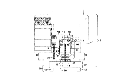
Figure 1 is a frontal ~iew of the adhesive supply unit with the service block ina horizontal position for adhesive bead pattern formation.
Figure la is a cross-sectional view drawn along line la-la of the adhesive supply
unit with the service block in the horizontal position.
Figure 2 is a frontal view of the adhesive supply unit with the service block ina vertical position for therrnoplastic adhesive sinusoidal pattern formation.
Figure 2a is a cross-sectional view drawn along line 2a-2a of the adhesive supply
unit with the service block in the vertical position.
CA 0220873~ 1997-06-2~
DESCRIPTIOI~ OF l ~E PREFERRED EMBODIMENT
Figure 1 illustrates one of the several possible embodiments of the
multipositional apparatus 2 contemplated by this invention.
As shown in Figure 1, the manifold 10 with a plurality of attachment apertures
11 is connected to the adhesive supply unit 1 used for heating and containing the
thermoplastic adhesive prior to being dispensed upon the containers at the uppermanifold portion 14 of the manifold 10 by a manifold attachment means 40. The
manifold 10 functions as a mechanism to which all of the various parts of the
multipositional apparatus 2 are attached.
As shown in Fi_ure 1, in one embodiment, the manifold attachment means 40,
consists of at least one bolt 16 for securing the manifold 10 to the adhesive supply unit
1. The bolt 16 is inserted into at least one of the attachment apertures 11 located at
the upper manifold portion 14. The bolt 16 is then attached to the adhesive supply
unit via conventional means.
In the first position, as shown in Figure 1, the manifold 10 is removably
attached to the service housing 20 by a multipositional attachment means 28. Theservice housing 20 provides an adhesive port, air pressure, and electrical power to the
module.
As shown in figure 1, the multipositional attachment means 28, when in the
second position may comprise at least one bolt 16 which secures the service housing
20 to the manifold 10. At least one bolt 16 is inserted into at least attachmentaperture 11 at the front portion 26 of the manifold 10. The bolt 16 is then attached
to the service housing 20 via conventional means. The service housing 20, when
CA 0220873 7 1997 - 06 - 2,
attached to the front portion 26 of the manifold 10, as shown in figure 2, is attached
in the second position, to dispense sinusoidal spray.
- As shown in Figure 1, when in the first position, the service housing 20 is in a
horizontal position and dispenses thermoplastic adhesive in a bead pattern. As shown
in Figure 2, when in the second position, the service housing is in a vertical position
and dispenses thermoplastic adhesive in a sinusoidal pattern.
The module 12 is removably mounted to the front wall 30 of the service
housing 20 by a module attachment means 58 via conventional methods.
A nozzle 34, which produces a plurality of thermoplastic adhesive patterns, as
shown in Figure la, is removably attached to the lower portion 50 of the module 12
by a nozzle attachment means 52. A second tip attachment 54 is removably attached
to the nozzle and produces a sinusoidal pattern of thermoplastic adhesive while in the
second position. Further, a first tip attachment 56 is removably attached to the nozle
34 and produces a bead pattern of thermoplastic adhesive while in the first position.
As shown in Figure la, in one embodiment, an adhesive port 178 is positioned
vertically in the manifold 10. The adhesive port 178 consists of an upper portion 62,
a body 64, and a lower portion 66. The lower portion 66 branches into a side outlet
168 and a lower outlet 170. The upper portion 62 of the adhesive supply 1 unit is
cooperative with an inlet 68 to the adhesive port 178.
The multipositional attachment means 28, when in the first position may
comprise at least one bolt 16 which secures the service housing to the manifold 10.
At least one bolt 16 is inserted into at least one attachment aperture 11 at the bottom
portion 80 of the manifold 10. The bolt 16 is then attached to the service housing 20
via conventional means. The service housing 20, when attached to the bottom portion
CA 0220873~ 1997-06-2~
80 of the manifold 10, as shown in figure 1, is attached in the first position, in order
to dispense bead spray.
As shown in Figure la, in one embodiment, when in use, in the first position,
the service housing 20 is mounted to the lower outlet 170 via conventional mounting
S means. In this configuration, the side outlet 168 of the adhesive port 178, which is not
in use, is blocked off with a blocking means 180. The blocking means 180 may consist
of a blocking plate 182. In this configuration, the thermoplastic adhesive dispersed
from the nozzle 34 is in a bead pattern.
As shown in Figure 2a, in one embodiment, when in use, in the second position,
the service housing 20 is mounted to the side outlet 168 via conventional means. The
lower outlet 170 is blocked by a blocking means 180. As shown in Figure 2, in one
embodiment of the invention, the blocking means consists of a blocking plate 182.
Other variations of this invention are contemplated by this application, and thescope of the invention is to be limited only by the followin~ claims.