Note: Descriptions are shown in the official language in which they were submitted.
CA 02208736 1997-06-2~
W O 96/20655 PCTrUS9~ 803
METHOD AND APPARATUS FOR MINIMALLY INVASIVE TREATMENT
OF CHRONIC VENOUS INSUFFICIENCY
BACgGROUND OF THE lNv~iNlloN
This invention relates to the correction of
incompetent venous valves or venous valvuloplasty, and more
particu].arly to minimally invasive correction of venous
insufficiency using a catheter based system to deploy an
appliance or a prosthesis to repair or augment a valve in a
vein.
The human venous system of the lower limb consists
essentially of the superficial venous system and the deep
venous system with perforating veins connecting the two
systems. The superficial system includes the great saphenous
vein and the small saphenous vein. The deep venous system
includes the anterior and posterior tibial veins which unite to
form the popliteal vein which in turn becomes the femoral vein
when joined by the small saphenous vein. The venous systems
contain a plurality of valves for directing blood flow to the
heart.
Venous valves are usually bicuspid valves, with each
cusp forming a sack or reservoir for blood which, under
pressure, forces the free edges of the cusps together to
prevent retrograde flow of the blood and allow only antegrade
flow to the heart. When an incompetent valve attempts to close
in response to a pressure gradient across the valve, the cusps
do not seal properly and retrograde flow of blood occurs.
,
CA 02208736 1997-06-2~
W O 96/20655 PCTfUS95/14803
--2--
There are two chronic venous diseases in which incompetence of
venous valves is thought to be an important factor in the
pathophysiology. These are varicose veins and chronic venous
insufficiency.
Chronic venous insufficiency is a problem caused by
hydrodynamic forces acting on the lowest part of the body, the
legs, ankles and feet. As the veins dilate due to increased
pressure, the valves in the veins become less able to withstand
the weight of the blood above them. This causes the veins to
dilate further and the valves in the veins to fail. As they
fail, the effective height of the column of blood above the
feet and ankles grows longer, and the weight increases with an
increase in the pressure exerted on the tissues of the ankle
and foot. When the weight of that column reaches a critical
point because of enough dilation and valve failures, the person
begins to have ulcerations of the ankle which start deep and
eventually come to the surface. These ulcerations are very
difficult to heal because the weight of blood causing them
still exists, with the tendency to enlarge the ulcer, and
because they are deep, often to the bone.
Chronic venous insufficiency consists of hypertension
of the lower limb in the deep, perforating and often
superficial veins with associated pigmentation, pain, swelling
and ulceration. Existing treatments for chronic venous
insufficiency are less than ideal. The only therapies
currently available include elevation of the legs for twenty
minutes every two hours, elastic support hose to compress the
veins externally and surgical repair or replacement of the
CA 02208736 1997-06-2~
W 096/20655 PCTrUS95/14803
--3--
valves by grafting vein from the person's arm into the leg.
These methods are variably effective. Moreover, surgery has
its associated complications with risk to life and is usually
very expensive. Similarly, the palliative therapies require
major lifestyle changes for the patient. Also, without
repairing the valves, even if the ulcers are healed, the ulcers
always recur unless the patient continues to elevate the legs
and to use support hose continuously.
Chronic venous insufficiency is essentially caused by
venous hypertension and chronic venous stasis due to valvular
incompetence both of a primitive nature (or primary or
essential or idiopathic) and of a secondary nature following
past illnesses of the venous system (generally speaking, deep
venous thrombosis or phlebitis). In the case of venous
valvular incompetence, the doctor has no efficacious drugs at
his disposal, and the surgeon does not have ready access to
artificial venous valves; whereas, valves of various types for
heart diseases, etc. have been available for many years. Some
methods of valvular reconstructive surgery may allow the
recovery of valvular function in certain cases. However, the
use of reconstructive surgery is obstructed by the delicate
nature and irreversible damage of the valvular structures.
The varicose vein condition consists of dilatation
and tortuosity of the superficial veins of the lower limb and
resulting cosmetic impairment, pain and ulceration. Primary
varicose veins are the result of primary incompetence of the
venous valves of the superficial venous system. Secondary
varicose veins occur as the result of deep venous hypertension
CA 02208736 1997-06-2~
W O 96/20655 PCTrUS95114803
which has damaged the valves of the perforating veins, as well
as the deep venous valves.
The initial defect in primary varicose veins often
involves localized incompetence of a venous valve thus allowing
reflux of blood from the deep venous system to the superficial
venous system. This incompetence is traditionally thought to
arise at the saphenofemoral junction but may also start at the
perforators. Thus, gross saphenofemoral valvular dysfunction
may be present in even mild varicose veins with competent
distal veins. Even in the presence of incompetent perforators,
occlusion of the saphenofemoral junction usually normalizes
venous pressure.
The initial defect in secondary varicose veins is
often incompetence of a venous valve secondary to hypertension
in the deep venous system. Since this increased pressure is
manifested in the deep and perforating veins, correction of one
site of incompetence could clearly be insufficient as other
sites of incompetence will be prone to develop. However,
repair of the deep vein valves would correct the deep venous
hypertension and could potentially correct the secondary valve
failure. Apart from the initial defect, the pathophysiology is
similar to that of varicose veins.
Prior art prostheses include artificial venous valves
and artificial valves for the heart and other anatomy which are
adaptable for use in a vein. One such disclosed venous valve
is comprised of an annular support member or ring defining an
opening therethrough, including leaflets hingedly attached to
the support ring for opening and closing the support ring
CAW096/206S5 PCT~S9511~803
--5--
opening in a manner permitting substantially unidirectional
flow therethrough. Such valves are designed to be sutured or
sewn into place within a blood vessel during a lengthy open
surgery. The support ring of the valve is secured within a
~ 5 flexible fabric tube at a location generally medially of the
tube. The blood vessel then is completely severed to provide
two free ends; and each end of the fabric tube, within which
the valve is secured, is sutured or sewn to a corresponding end
of the free blood vessel to effectively splice the blood
vessel.
Such prior art valves are likely to result in
clotting of blood about the support member of the valve. Such
clotting is, of course, undesirable and may be promoted by the
fabric tube commonly utilized when suturing the valve into
place. In particular, the fabric of the tube normally defines
regions or voids within which blood is permitted to accumulate
and clot. Furthermore, the fabric of the tube and support ring
may provide gaps or spaces between the outer surface of the
support ring and the inner wall of the fabric tube. Such gaps
may cause the buildup of blood, thereby promoting clotting.
SUMMARY OF THE lNv~NllON
Briefly, and in general terms, the present invention
provides a much less painful, less expensive and faster method
for solving the underlying problems of venous valve insuff-
iciency and uses a unique repair system, including a delivery
catheter for placement of an appliance or a prosthesis. The
system and method of the invention eliminate the need for open
CA 02208736 1997-06-2~
W096/20655 PCT~S95/14803
surgical valve repair procedures, obviate the need for arm vein
transplantation into the leg, and allow patients to return to
their former active lifestyles without the limitations
currently associated with the treatment of this condition.
For the sake of convenience, the invention will be described in
relation to the correction of incompetent valves in the venous
system of the lower limb in man; however, it is to be
understood that the invention is not limited thereto.
The procedure for repair of incompetent venous valves
may be accomplished by any qualified physician under
fluoroscopic observation. First, the skin on the patient's
ankle is cleaned and disinfected. A needle is inserted into
the saphenous vein at the ankle and a wire is threaded through
the needle as per the Seldinger technique. Alternatively, a
cutdown to the saphenous vein is performed.
Once access to the vein is obtained as above, a
delivery catheter is placed into the vein either over a wire or
directly. The catheter is used to inject x-ray contrast
material so that the venous valves can be identified. The
catheter is moved up the vein toward the heart and is
positioned at the level of the first functional valve or as far
as the femoral vein. If the Seldinger technique is used, the
wire would first be placed up to the femoral vein and the
catheter would then be passed ovèr the wire as described above.
Once the incompetent valve to be repaired is
identified by injected contrast through the delivery catheter
and the catheter is positioned at that valve, a clip appliance
is deployed from the catheter and affixed to the valve. More
CA 02208736 l997-06-2~
W 096/20655 PCTrUS95/14803
--7--
than one clip may need to be placed. The catheter may contain
more than one clip, or may have an integral clip making up its
tip, so that a new catheter would be used for each clip placed
and for each valve repaired. Alternatively, a prosthesis, such
as an artificial valve, may be deployed from the catheter.
After the clip is placed, the delivery catheter is
positioned proximate the next venous valve to be repaired. All
valves may be repaired, or selective valves may be repaired.
If the catheter design is a single clip type, then the wire and
catheter is positioned proximate the next valve. The wire is
left at that level in the vein while the catheter is removed.
Another catheter and clip assembly is then placed over the wire
with a repeat of the above procedure. If a catheter containing
multiple clips is used, then the catheter is merely positioned
at each valve wherein another clip appliance is deployed.
The delivery catheter is repositioned and clip
appliances are deployed on sequentially lower valves until all
desired valves are repaired and functionally competent. Valve
competence may be determined by contrast injection or Doppler
probe measurement. A competent, functioning valve demonstrates
Doppler flow toward the heart with leg compression at the calf,
but no flow in the reverse direction past the repaired valve
with compression of the thigh. Once each valve is repaired,
the wire and catheter are completely removed from the patient's
leg.
Alternatively, a prosthesis, such as a replacement
valve, or a natural or processed replacement vein may be placed
by a catheter system. The prosthesis may be deployed similar
CA 02208736 1997-06-2~
W096/20655 PCT~S95/14803
to the clip appliance. Likewise, the replacement vein is
placed at the proper position within the patient's vein and
affixed with a stent having spikes or a similar attachment
system. If necessaryl the prosthesis, vein and stent are
expanded and secured within the lumen of the vein by a balloon,
spring or other method.
The clip appliance is made of a biocompatible
material, such as a polymer, metal or fabric. The clip is
constructed so that it will fit on or within the delivery
catheter. The clip is configured with spreadable legs so as to
fit over both sides of the venous valve. The clip is further
configured to close either by a spring action or by compression
so as to lock the legs together over the venous valve. The
clip may have a single set of legs or may have multiple sets of
legs. Conversely, the appliance could be staple-like and
pierce or go through the valve as opposed to over the top of
the valve leaflets.
The delivery catheter of the present invention is
configured to position the appliance or prosthesis within the
vein proximate the venous valve to be repaired. The catheter
is capable of twisting or otherwise moving to allow for proper
placement of the appliance or prosthesis. In addition, the
catheter prevents the appliance or prosthesis from being
inadvertently released into the bloodstream of the vein, etc.
The catheter may be further configured for expanding or
compressing a clip appliance, aligning the clip on each valve
and assuring that the clip is securely fastened to the valve.
Also, the delivery catheter tip would actually be the clip and
CA 02208736 1997-06-2~
W096/20655 PCT~S9S/14803
_g_
would be disconnected from the rest of the catheter after
appropriate placement. The catheter also may be configured to
deliver x-ray contrast material. The delivery catheter, guide
wire and appliance or prosthesis should be constructed of
materials which would allow their visualization under
fluoroscopy, x-ray, ultrasound or other imaging techniques.
These and other features and advantages of the
present invention will become apparent from the following more
detailed description, when taken in conjunction with the
accompanying drawings which illustrate, by way of example, the
principles of the invention.
BRIEF DESCRIPTION OF THE DRAWINGS
FIGURE 1 shows a perspective view in partial cross-
section of a vein having both competent and incompetent valves.
FIG. 2 is a plan view of a clip appliance of thepresent invention secured to the distal end of a delivery
catheter.
FIG. 3 is a perspective view of the clip appliance
and delivery catheter of FIG. 2.
FIG. 4 is a partial cross-sectional view showing the
clip appliance of FIG. 2 inserted into a vein proximate an
incompetent valve.
FIG. 5 is a partial cross-sectional view showing the
clip appliance of FIG. 2 positioned with the legs of the
appliance over the cusps of an incompetent valve.
FIG. 6 is a partial cross-sectional view showing the
clip appliance of FIG. 2 positioned with the legs of the
CA 02208736 1997-06-2~
W O 96/20655 PCTrUS95/14803
--10 -
appliance closed and locked onto the cusps of a valve.
FIG. 7 is a partial cross-sectional view showing the
clip appliance of FIG. 2 disengaged from the delivery catheter.
FIG. 8 is a plan view of an alternative embodiment of
the clip appliance of the present invention shown with a
gripping device.
FIG. 9 is a partial cross-sectional view of the clip
appliance and gripping device of FIG. 8 configured within the
distal end of a delivery catheter.
FIG. 10 is a plan view of an alternative embodiment
of the clip appliance of the present invention shown with a
locking plate and delivery catheter.
DET~TT~T~n DESCRIPTION OF THE PREFERRED EMBODIMENTS
As shown in the exemplary drawings, the invention is
embodied in a clip appliance 15 and delivery catheter 16 for
use in a vein 20 for minimally invasive treatment of chronic
venous insufficiency. As shown in FIG. 1, venous valves are
usually bicuspid valves and are disposed within muscle tissue
21 and may be deep near a bone 22. In a normal and competent
valve 24, each cusp 25 forms a sack or reservoir 26 for blood
which, under pressure, forces the free edges of the cusps
together to prevent retrograde flow of the blood and allow only
antegrade flow to the heart (Arrow A). When an incompetent
valve 30 attempts to close in response to a pressure gradient
across the valve, the cusps do not seal properly and retrograde
flow of blood occurs.
In accordance with the present invention, an
CA 02208736 1997-06-2~
W096/20655 PCT~S95114803
appliance or prosthesis 15 is positioned by the delivery
catheter 16 within the vein 20 adjacent an incompetent valve
30. The catheter is used to position an appliance so as to
close the cusps 25 of the venous valve or otherwise reconstruct
the valve to return it to its normal and competent function.
Similarly, the catheter may be used to deliver a prosthesis,
such as an artificial valve, proximate an incompetent valve or
between incompetent valves so as to prevent retrograde flow of
the blood moving through the vein. Thus, the system and method
of the invention eliminate the need for open surgical valve
repair procedures, such as vein transplantation into the leg,
and allow patients to return to their former active lifestyles
without the limitations currently associated with the treatment
of chronic venous insufficiency.
As shown in FIG. 2, an embodiment of the appliance
comprises a clip 15. The clip appliance comprises a first leg
40 connected to a biasing member 41. The biasing member is
connected to a second leg 42, which is shorter than the first
leg. The purpose of having a longer first leg is to ensure
that the first leg enters one side of the cusp 25 of the
incompetent valve 30 prior to inserting the second leg into the
other cusp of the valve. The legs have serations or bends 44
which assist the clip in gripping the valve cusps.
The clip appliance 15 further comprises an adjustment
mechanism 50 consisting of a screw-like member 52 attached to
a cord 53 which is secured to the first leg 40 and the second
leg 42. The delivery catheter 16 is used to manipulate the
clip appliance through the anatomy and activate the adjustment
CA 02208736 1997-06-2~
W 096/20655 PCTrUS95/14803
-12-
mechanism. The catheter is removably secured by threads or
other means to the clip at the proximal end 54 of the
adjustment screw. As the adjustment screw is rotated (Arrow
B), the cord shortens, thereby moving the first leg and the
second leg closer together (Arrow C). Continued rotation of
the adjustment screw in one direction (e.g., counterclockwise)
will move the legs in close proximity to each other.
The clip appliance 15 further comprises a locking
mechanism 55. The locking mechanism includes a locking hook 56
fixed on the second leg 42. The hook is configured to be
secured over the first leg 40. As the adjustment mechanism
moves the first leg closer to the second leg, the locking hook
and first leg engage, thereby holding the legs of the clip
appliance together in position. When the clip legs are in the
closed position, the cusps 25 of the incompetent valve 30 are
brought closer together to ensure competency of the valve.
Likewise, the walls of the vein are brought closer together
along the axis of the valve perpendicular to the direction of
the clip closing. Once the lock mechanism is engaged, the
delivery catheter 16 may be rotated in the opposite direction
(e.g., clockwise) to release the clip appliance from the
catheter.
In an alternative embodiment of the clip device, the
adjustment means may comprise of a small diameter winder or
screw member (not shown). The function of the smaller winder
is basically the same as described heretofore, such that
turning the winder causes the legs of the clip device to move
together and for the locking mechanism to engage. The smaller
CA 02208736 1997-06-2~
W 096/20655 PCTrUS9~/14803
winder, however, is adapted to be used with a smaller diameter
catheter and requires less torque and more winding to close the
legs.
As depicted in FIG. 3, the delivery catheter 16 of
the present invention includes an elongate tubular member 60
configured for traversing the vein of a human patient. The
catheter may be comprised of various materials which are
biocompatible with the human anatomy. Such materials include
stainless steel, PEBAX, and similar plastics. Such plastics
may be injected or otherwise made with radiopaque material for
visualization under fluoroscopy. In addition, radiopaque
markers 62 may be embedded or otherwise secured to the catheter
for observation under x-rays for fluoroscopy. For ease of
traversing the vein, the catheter may be configured with an
outer sheath (not shown). Such an outer sheath is configured
to cover the distal end 65 of the catheter and the appliance or
prosthesis, and is coaxial and separately retractable from the
elongate tubular member 60.
The distal end 65 of the delivery catheter 16 is
threaded or otherwise configured so as to engage the proximal
end 66 of the adjustment mechanism of the clip device. The
catheter may be turned, twisted and torqued from the proximal
end 66. When the delivery catheter is engaged with the clip
appliance 15, turning the proximal end of the catheter rotates
its distal end, thereby rotating the adjustment screw 52 or
disengaging the catheter from the clip. The proximal end of
the catheter may include a "T-handle" 68 for ease of use by the
surgeon. Similarly, the proximal end may be configured with a
CA 02208736 1997-06-2~
W O 96/20655 PCTrUS9S/14803
-14-
releasable locking mechanism to secure the outer sheath to the
elongate tubular member 60. Alternatively, the distal end of
the catheter is configured to deploy other prosthesis or
appliances and the proximal end is similarly configured.
FIGS. 4-7 detail the method of the present invention
for minimally invasive valvuloplasty for treatment of chronic
venous insufficiency using the clip appliance 15 and delivery
catheter 16 of FIGS. 2 and 3. Alternatively, the method is
contemplated to be used with any suitable appliance or
prosthesis for repair, reconfiguration or replacement of
incompetent venous valves. In particular, the method of
deploying a prosthesis is especially suited for deploying and
implanting one or more natural or artificial venous valves.
To start the procedure, the patient is placed onto a
gurney or procedure table (not shown) with the feet dependent
to fill the veins of the leg. The ankle of patient is prepped
with antiseptic solution. The ankle is tourniqueted with a
band and the long saphenous vein is entered with an 18~ or
similar needle. A cutdown could also be performed rather than
using the needle to enter the vein. The tourniquet is then
removed.
A guide wire (not shown) is inserted into the vein 20
according to the well known and practiced Seldinger technique
and the needle is removed. The wire is advanced to the level
of the incompetent valve 30 which is to be repaired. Alterna-
tively, the delivery catheter could be passed within the vein
after insertion through the skin, without the need to advance
the wire to that level. Fluoroscopy, x-ray, ultrasound, or a
CA 02208736 l997-06-2~
W 096/20655 PCTrUS95/14803
-15-
similar imaging technique is then used for specific placement
of the catheter and confirmation of position.
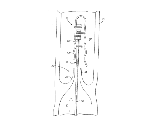
Referring to FIG. 4, the delivery catheter 16 is then
inserted upon the wire and is fed up the leg through the vein
into the femoral vein to the level of the most proximal
incompetent valve 30. The distal end 65 of the catheter and
the clip appliance 15 are advanced distally (Arrow D) through
the vein while the outer sheath of the catheter (not shown) is
held in place. This relative motion may be accomplished by a
ratchet-like mechanism, by pushing the elongate tubular member
60 while holding steady the sheath, or by a cabling approach.
As the appliance is advanced out of the sheath, the legs 40, 42
of the clip separate to a width greater than the distance
between the valve cusps 25, as shown in FIG. 4. Other
appliances or prostheses may be positioned in a like manner.
As shown in FIG. 5, the entire delivery catheter 16
is then gently pulled in a proximal direction (Arrows E) within
the vein 20 so that the legs 40, 42 of the clip appliance 15
catch on the outside of each 70 leaflet within the cusps 25 of
the valve 30. In order to accomplish this, the patient may
need to be placed into a Trendelenburg position or the veins
may need to be exsanguinated using an elastic wrap around the
leg and a tourniquet to prevent arterial inflow. The placement
of the appliance or prosthesis may also be performed under
direct visualization by an optical device such as a camera or
fiber optic pathway or under fluoroscopy or x-ray or
transillumination.
The clip appliance 15 may be posltioned in the center
CA 02208736 l997-06-2~
W 096/20655 PCTrUS9~/14803
-16-
of the width of the incompetent valve 30, on the edges or in
between the center and the edges. Alternatively, the clip may
be configured with multiple sets of legs which could be placed
so that one set of clips is at each end of the valve width.
Once the clip is positioned, the adjustment mechanism 50 iS
activated by turning the ratchet or screw-down assembly of the
clip as in one embodiment tFIG. 2), by manipulating a cable
within the catheter in another embodiment ( FIG. 9), or by
pulling down a plate as in another embodiment (FIG. 10).
Referring to FIG. 5, the delivery catheter 16 is
rotated (Arrow F) to tighten the cord 53 and move the legs 40,
42 of the clip appliance 15 towards each other (Arrows G). The
legs are closed until the hook 56 of the locking mechanism 55
engages the first leg. As the legs of the clip close, the
leaflets 70 of the cusp 25 of the incompetent valve 30 are
moved together. Likewise, the walls 72 of the vein 20 are also
drawn together.
As shown in FIG. 7, the delivery catheter 16 is then
disconnected either by unscrewing or otherwise unlocking the
catheter from the clip appliance 15. The catheter is then
moved proximally (Arrow H) within the vein 20 to clear the
elongate tubular member 60 from the valve 30. As the catheter
is removed from the valve, the legs 40, 42 of the clip push the
leaflets 70 of the valve cusp 25 together until the valve is
closed. At this point in the procedure, the valve is repaired
and should be competent.
Once the clip appliance 15 is in place, another clip
could be placed onto the same valve 30 if necessary. This
CA 02208736 l997-06-2~
W O 96/20655 PCT~US95/11803
-17-
might be done with the same delivery catheter 16 in the
multiple-clip embodiment (FIG. 9) or by removing the "spent"
catheter and inserting another in the same fashion as described
heretofore. After sufficient clips have been placed and the
catheter and wire are removed from between the repaired valve's
cusps, the valve is tested using either an injection of
contrast from a needle or catheter inserted proximal to the
repair and with visualization under x-ray or by Doppler probe
placed distal to the repaired valve. Compression of the leg or
vein cephalad to the repair would demonstrate reverse flow
should the valve be incompetent, and stopped flow if the valve
were competent.
Next, the wire would be pulled back to the level of
the next valve to be repaired, or the catheter would be placed
at that level through the valve cusps as described heretofore.
The same procedure would then be repeated for each subsequent
valve repair. Once all necessary clips were applied, the
catheter and guide wire would be removed. The access point of
the vein would be sutured closed if a cutdown had been
performed, or local pressure would be applied until bleeding
was controlled. A bandage would then be applied. A pressure
dressing may be necessary. Elastic support stockings may be
applied subsequently.
FIGS. 8 and 9 show an alternative embodiment of the
clip appliance 80 and a delivery catheter 82 having a distal
end which includes a mechanism for deploying a plurality of
clip appliances. The distal end of the catheter includes a
capsule 85 sized sufficiently to hold a plurality of clips.
CA 02208736 1997-06-2~
W096/20655 PCT~S95/14803
-18-
The distal end further includes a "U" or "V" shape tweezers-
like mechanism 86 for grasping the clips one at a time. The
delivery catheter is configured with a cable 87 which extends
from the proximal end of the catheter to the capsule. The
cable's distal end is secured to the closed end of the tweezers
and is disposed in a "U" shaped lumen 103 such that the open
end of the tweezers faces proximally. The cable 87 is secured
to the tweezers by a hinge 94 which allows manipulation of the
tweezers from the proximal end of the cable. Thus, the cable
and tweezers may be moved independent from the rest of the
delivery catheter.
As shown in FIG. 8, each clip appliance 80 is
configured in a "U" or "V" shape having a pair of legs 88 and
89 which are biased apart by the U-bend in the clip. Each leg
of the clip has an indent 90 which mates with one of a pair of
detents 92 on the legs of the tweezers 86. The tweezers are
further provided with pads 93 which are sized and positioned to
press the legs of the clip together when the tweezers are
pressed against the clip. The first leg 88 of the clip
appliance is provided with a niche 100 configured to accept a
barb-like detent on the clip's second leg 89. When the legs of
the clip are pressed together, the barb enters the niche,
locking the clip legs together.
Referring to FIG. 9, the capsule 85 of the delivery
catheter 82 is configured with a recess 95 having a proximal
end in which a plurality of catheter appliances 80 may be
placed for deployment. The tweezers 86 are movably disposed at
the distal end of the capsule recess. The proximal end 96 of
CA 02208736 l997-06-2~
W096/20655 PCT~S951148~3
the capsule slot is tapered so that when the tweezers are moved
proximally, the tweezers close around a clip, such that the
tweezer detents 92 engage the clip indents 90.
A substantially oval slot or notch 98 iS configured
within a side of the recess in the capsule 85. The slot is
shaped and dimensioned so that when the tweezers 86 are moved
through the slot by manipulation of the cable 87, the tweezers
open the legs 88, 89 of the clip appliance 80. Similarly, the
slot is shaped such that when the capsule is moved proximally
over the tweezers, the clip is closed and locked by the barb
l0l entering the niche l00.
Thus, the clip appliance 80 may be secured to the
cusp of a incompetent valve by manipulation of the cable 87 and
tweezers 86. After deployment of a clip, the tweezers may be
moved into the capsule 85 by manipulation of the cable. The
hinge 94 is configured to permit the tweezers to move in and
out of the slot 98 as the capsule and tweezers are moved
relative to each other. Once the tweezers are returned to the
capsule, the delivery catheter 82 may be moved so that the slot
iS adjacent the next valve to be repaired.
An alternative embodiment of a clip appliance is
shown in FIG. l0. The "U" shaped clip is configured with a
plate 112 which is used to secure the legs 114, 115 of the clip
together. The first leg 114 is longer than the second leg 115
and both legs have serations or bends for gripping a cusp of a
venous valve. The plate is configured with holes in which the
legs of the clip are disposed. The plate is further configured
with a threaded hole 120 for receiving the distal end of an
CA 02W 096/20655 PCTrUS95/14803
-20-
elongate tubular member 122 of a delivery catheter. Theelongate tubular member is configured with a central lumen 123
for slidably receiving a pusher rod 125.
The clip appliance 110 is positioned within a vein
and over a incompetent valve by the delivery catheter as
described heretofore. Once in position, the tubular member 122
is moved in a proximal direction and the pusher rod 125 is held
fixed. Movement of the tubular member causes respective
movement of the plate 112 (Arrow I). The bend of the clip
appliance between the legs 114, 115 is configured with a cup
128 which receives the distal end 126 of the pusher rod. As
the plate is moved proximal to the legs of the clip, the legs
are pushed together. Each leg is configured with a large bend
130 which acts as a stop catch for the plate, and locks the
legs together when the plate is moved into the stop catch.
After the plate is positioned in the stop catch, the tubular
member is unscrewed or otherwise released from the plate and
the tubular member and pusher rod are moved proximally away
from the valve.
As can be readily ascertained from the disclosure
herein, the surgical procedure of the present invention is
accomplished without the need for prolonged hospitalization or
post-operative recovery. The novel apparatus and method allow
for curative restoration of venous valvular function without
the need for continued lifestyle changes, such as fre~uent leg
elevation, the wearing of relatively uncomfortable elastic
support stockings or prolonged treatment of recurrent venous
stasis ulcers. The minimally invasive procedure provides for
CA 02208736 1997-06-2~
W O 96/20655 PCTrUS95/1~803
-21-
more rapid healing of foot ulcers than is currently possible
because of the functional restoration of the valves. Moreover,
the need for surgery of the arm and leg for transplantation of
arm vein valves into the leg is no longer necessary.
The new efficacious procedure is expected to have
much less morbidity, thereby making it possible that early
treatment of venous disease at the stage of varicose veins or
pain and swelling without the advanced stages of ulceration
could be treated. This would allow early treatment and
prevention of more serious complications such as ulceration,
thrombophlebitis and thromboembolism. The cost of treatment
and complications due to venous dlsease would be significantly
reduced because there would be no need for hospitalization for
this procedure and also by the reduced need for subsequent
treatment and hospitalization which currently are needed due to
the palliative nature of most of the current methods of
therapy.
While several particular forms of the invention have
been illustrated and described, it will be apparent that
various modifications can be made without departing from the
spirit and scope of the invention. Accordingly, it is not
intended that the invention be limited, except as by the
appended claims.