Note: Descriptions are shown in the official language in which they were submitted.
CA 02208796 1997-06-2~
PROSTHESIS WlTH VARIABLE FIT
AND STRAIN DISTRIBUTION
BACKGROUND OF THE INVENTION
3 The invention relates to implantable bone prostheses, and more particularly to joint
4 prostheses that attach to bone and have properties, such as fit and fill, which change after
implantation.
7 Joint prostheses are well known in the art and have long been used to replace natural
8 joints, in~lu-ling knees, hips, shoulders, and elbows. Such prostheses may include a projecting
9 part, such as a stem configured to mount in or attach to the remaining natural bone and secure
the prosthesis. The size, shape and materials of a joint prosthesis are critical to ensuring proper
11 fit within a patient's body, and may also affect the extent of bone growth into and surrounding
12 the prosthecic, both of which contribute to fixation of the prosthesis within the patient.
13
14 Earlier versions of joint prostheses have relied extensively upon bone cements to fix a
prosth~-cic within natural bone.
16
17 Cements provide the high degree of initial fixation necessary for healing following
18 surgery but result in a very stiff overall structure, are prone to loosening with time, and can
19 provoke tissue reactions or systemic responses. Nonetheless they remain widely used, although
in current practice they may be applied over smaller regions than before, or be used in
21 conjunction with other modes of fixation. Over the longer term, fixation now also relies on the
22 provision of textured regions, and regions which enhance bone growth by providing a structure
23 or framework of porous material, with or without coatings of bone-growth enhancement
24 materials, such as hydroxyapatite or calcium oxide materials and various organic growth
promoters, to bring about secure coupling by intergrowth of new bone material. In some
26 constructions, a bio-absorbable material is also used to fill irregularities, allowing pores or
CA 02208796 1997-06-2~
cavities in a permanent metal body to open up and become filled in coordination with ong,oing
2 regeneration and ingrowth of the surrounding bone.
4 With these more complex constructions, resorption of a coating or filler, and its
S replacement by bone ingrowth can cause the properties of the prosthesis (e.g., stiffness) to
6 change over time. For example, a particular joint prosthesis, such as a hip stem, may have a
7 stiffness which is acceptable at the time of implantation, but which becomes either too flexible
8 or too stiff subsequent to implantation as a result of bone ingrowth and dissolution of material.
9 Conversely, engineering an implant with properties at levels which are desirable for the long
term may result in a prosthesis which has prope,lies that are not suitable at the time of implant.
11
12 Some attempts have been made to improve the fit and fill characteristics of joint
13 prostheses during healing by regulating the timing of bone ingrowth, generally by selection of
14 pore size and coating solubility.
16 U.S. Patent No. 4,713,076 discloses a bone implant coating formed of a calcium-based
17 filling material and a binding agent, both of which are bio-absorbable. The filling m~ l is
18 in the form of porous spherical particles with a diameter of about 10-200 micrometers and a pore
19 volume of 25-80%. The ultrastructure of the coating is stated to promote rapid ingrowth of bone
into the coating.
21
22 U.S. Patent No. S,258,034 discloses a hip stem prosthesis that provides controlled bone
23 ingrowth. A bone ingrowth-promoting coating is provided at a proximal part of the prosthesis
24 to promote rapid bone ingrowth at that region of the prosthesis. The distal end of the prosthesis,
where rapid bone ingrowth is not desired, includes an absorbable coating or sleeve. The
26 thickness of the absorbable coating or sleeve is designed to be absorbed over the period of time
27 during which bone ingrowth at the proximal end of the femoral stem would normally take place.
28
29 U.S. Patent No. 5,007,931 discloses a femoral stem implant in which longitudinal
channels are made in the stem to reduce its section modulus, and elongated strips of a porous
' CA 02208796 1997-06-2~
material are bonded only to the floors of the channels keeping destr~lctive bending stresses low
2 and avoiding notching. The stem is shaped for cementless fixation in a bore prepared in the
3 femur.
S Despite advances made thus far in the design of joint prostheses, there remains a need
6 for a joint prosthesis in which the mechanical and physical properties of the prosthesis stay
7 appropriate in different phases of the post-implantation period.
9 It is thus an object of the invention to provide a joint prosthesis in which mechanical and
physical plopelLies, including shape, size, stiffness, strength and density, vary over time in a
11 controlled fashion after implantation.
12
13 A further object is to provide a joint prosthesis having physical and mechanical properties
14 that evolve from a first plurality of properties which are advantageous at the time of implantation
to a second plurality of properties which are advantageous at a later time.
16
17 A further object is to provide a joint prosthesis that possesses short term stiffness to
18 promote good fixation, and evolves long term bending flexibility to improve its performance and
19 useful life.
21 It is yet another object to provide a joint prosthesis that is modular in the sense that
22 adjustm~ntc and modifications to the prosthesis are readily made by a surgeon in the operating
23 room environment by interch~nging or modifying components to tailor the device to a specific
24 patient.
26 The attainment of these and other objects of the invention will be apparent to those skilled
27 in the art upon reading the disclosure that follows.
CA 02208796 1997-06-2~
SUMMARY OF THE INVENTION
3 The present invention achieves one or more of the foregoing objects by providing a joint
4 prosthesis having a first part, including a body formed of metal or the like which is permanent
and which constitutes the essential overall shape and structural component of the prosthesis, such
6 as a shelf, plate or stem. The body has a plurality of negative surface features such as deep
7 grooves, tunnels or pits, or valleys or slots defined between or within projecting walls, wings,
8 fingers or flutes. A second part, which is non-permanent, is attached to the body, and provides
9 both a fit, and a time-evolving structural coupling tO surrounding bone, such that the prosthesis
initially fits the patient's remnant bone, while the mechanical properties evolve and shift with
11 time in vivo to change the position or distribution of its coupling to bone along its length.
12
13 In one aspect of the invention, illustrated by a femoral stem, the negative surface features
14 formed in the body or structural component take the form of axially extending grooves made,
for example, at the distal end of the metallic structural component or at a position intermediate
16 the proximal and distal ends of the metallic structural component. The negative surface features
17 can also include one or more transversely oriented grooves formed in the met~llic structural
18 co,.,ponent, or one or more bores formed in the metallic structural component. The negative
19 surface features may also be defined by axial flutes in a beam-like structure, or by slots which
separate the body into prongs or fingers. Preferably, the second part is a bio-absorbable
21 component which is adhered to, frictionally engaged within or mechanically interlocked with the
22 negative surface features and which thereby augments the structural body, for example, by
23 increasing its size and/or bending stiffness, and forms a compound unitized pros~hesic. The
24 second part extends at least partially beyond or outside of the structural body to provide initial
points of contact against surrounding bone in at least one region thus providing an initially rigid
26 fixation.
27
28 In one embodiment, the joint prosthesis is a modular set and the structural component
29 has formed therein one or more negative surface features that accommodate different ones of a
s~ ct~ble set of bio-absorbable inserts or attachments of varying geometries and dimensions.
CA 02208796 1997-06-2~
These second parts mecil~llically interfit ~4ith the stmctural component, and may come in a range
2 of sizes or shapes such as wedges, or plugs, caps or sleeves of different diameters to fit a range
3 of femoral hollow sizes. They also may be formed of materials having different resorbabilities,
4 stiffness~s or strengths for affecting load or strain distribution. This enables a surgeon to
5 assemble or modify during the course of a surgical procedure a configuration and size of a
6 prosthesis that is best for a given patient at the time of implant. Over time, and after
7 implantation, the properties of the implant change as the second component is resorbed and the
8 overall mechanical properties of the compound prosthesis and its attachments evolve.
In an illustrative implementation, a hip prosthesis has a femoral stem with metal stem
11 body and a biocompatible and bio-absorbable second component installed at a distal end of the
12 stem. The configuration and dirnensions of the bio-absorbable component are such that it has
13 a diameter that is greater than the nominal diameter of the first component of the hip stem, and
14 fits a bore made by one of the standard size femoral canal straight or tapered bone reamers. The
15 second component provides a distally tight fit at the time of implantation and augments the stem
16 to provide a relatively rigid structure. However, after implantation, the distal end bio-absorbable
17 co~l-pollent resorbs, increasing distal flexibility. During this post-implantation phase, new bone
18 growth concurrently provides a more rigid attachment at the proximal end. The less rigid shaft
19 thereby shifts its load and strain distribution so that an increasing portion of the load is applied
20 at the femoral metaphysis and is carried by the intermediate portion of the natural femur. This
21 results in a more natural loading of the femur with a strain distribution that counteracts bone
22 atrophy and resorption. Thus, the modular construction largely avoids bone stress shiplding.
23
24 The bio-absorbable co~ onent itself need not have ~~esses, and may take various forms
such as a coating, wedge, plug, cap, sleeve or insert. In general it serves both to provide initial
26 fit, and to control or guide the speed and extent of bone ingrowth. These two functions may be
27 achieved with a modular component. Alternatively, separate isolated bio-absorbable portions,
28 having the same or different resorption and growth characteristics, may implement both or
29 prim~nly a single one of these functions. For achieving initial fit and fixation, the second
component may include projections such as blade-like fins oriented along a direction of insertion,
CA 02208796 1997-06-2~
that, upon insertion, pro~ide an irrotational "scratch fit" against surrounding bone. It may have
2 one or more wing-like projections for anchoring or positioning the body. Furthermore, the bio-
3 absorbable component need not be a separate modular piece, but may include a mass of irregular
4 topology that extends into and through recesses or tunnels in the first, structural component, and
S projects outward therefrom to provide the initial external fit and a subsequent dissolution path
6 for natural bone ingrowth. In this case the mass may be molded in situ, for example by using
7 a deformable or viscous organic polymer, with a degree of cross-linking or hardening tailored
8 to achieve the desired resorption time. Similarly, the second component may include coatings
9 at one or more regions of the prosthesis, positioned to either enhance an initial interference fit,
or promote later bone growth, together with separate, modular attachments.
11
12 Advantageously by providing a bio-absorbable and a metal component together in a
13 compound or modular prosthesis, applicant separately and independently tailors the initial and
14 ultimate values of fixation strength, strain transfer and bending stiffness of the prosthesis at two
or more positions along the device. This new architecture achieves a high degree of initial
16 fixation and strength without sacrificing the mechanical characteristics required for long term
17 bone growth and compatibility.
18
19 BRIEF DESCRIPTION OF THE DRAWINGS
21 Th,ese and other features of the invention will be understood from the description below
22 together with illustrative examples and drawings, wherein:
23
24 FIGURE 1 shows a two-part modular prosthesis in accordance with the present invention;
26 FIGURES 2A-2C show sections through the prosthesis of FIGURE 1;
27
28 FIGURES 3, 3A and 3B show another embodiment of a prosthesis in accordance with
29 the present invention;
CA 02208796 1997-06-2~
FIGURES 4, ~A and ~B show another prosthesis;
3 FIGURE 5 shows representative bending stiffness of the prosthesis of FIGURES 1 or 3;
4 and
6 FIGURE 6 is a conceptual graph illustrating the form of evolving stress distribution in
7 bone.
9 DETAILED DESCRIPTION OF THE INVENTION
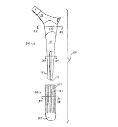
11 FIGURE 1 shows a side view of a hip prosthesis 100 according to a replesel-tative
12 embodiment of the present invention. Prosthesis 100 includes an elongated body or structural
13 part 110 and a distal cap or fitting part 120. The body 110 is adapted for insertion into the
14 hollow center of a femur, and extends from a metaphyseal region 114 shown at the top in the
drawing to a distal end 116, with the stem 115 in the intermediate portion being generally
16 tapered along two planes in a known manner for fitting within the femur. The structural body
17 110 is formed of bio-compatible metals or alloys. Exemplary metals include cobalt and titanium,
18 while exemplary alloys include Ti6AI4V or CoCrMo. In the illustrated embodiment, the distal
19 end 116 has the form of four separate elongated fingers 116a through 116d, shown in cross-
section in FIGURE 2A. Recause of their relatively small cross section, these fingers 16a
21 through 116d are capable of a relatively high degree of flexion or bending along their length in
22 a manner similar to but of lesser magnitude than a clothespin. It will be understood that
23 FIGURE 1 is intended to show a generic external contour, which might be more rounded, more
24 angular or otherwise correspond to known prostheses, and that as to the distal end, the FIGURE
is a schem~ic ~eplesentation only. That is, a person skilled in the art will understand that the
26 actual contour of the fingers, particularly at their junction with the solid mid portion 115 of the
27 stem, is to be configured to avoid the generation of stress cracks and provide a long and useful
28 fatigue life of the prosthesis. In general however it will be noted that the shape of the distal end
29 of the prosthesis involves deep grooves or entire through-slots 117 which separate the body of
the stem into smaller more bendable beam-like structural portions.
CA 02208796 1997-06-2~
The second component of the illustr~ted prosthesis is the dista] end cap 120, one
2 embodiment of which is shown in FIGURE 1, and illustrated in cross section in FIGURE 2B.
3 Unlike the structural component 110, the end cap 120 is formed of a temporary material such
4 as polylactic acid (PLA) or polydixanone (PDS), which is both bio-absorbable when implanted
in the body, and is configured to extend beyond or protrude from the metal component of the
6 distal stem portion. Suitable bio-absorbable materials include polyamino acids, polyacetates,
7 polyglycolates, poly (p-dioxanone), co-condensates thereof, copolymers thereof, gelatin,
8 collagen, and calcium phosphate-based materials. As illustrated, the cap 120 is an elongated
9 sleeve which fits around the fingers 116a through 116d, and fills the gaps therebetween,
resulting in a solid but compound, i.e., two-material, tip structure. The sleeve has a generally
11 cylindrical portion 127 which fits around the stem, and a plurality of cross-bars 123; 125 or
12 spoke-like members positioned to slide into the slots 117 of the body 110. The members 123,
13 125 may be dimensioned thicker than the slots 117, and may have a Shore D hardness selected
14 such that by wedging into the slots 117, the members are placed under compression to couple
the fingers 116 together. This rigidifies the distal end 116 at the time of implantation. Thus,
16 by filling the gaps between fingers, the resultant structure has a much higher bending stiffness
17 than the metal component alone, while it attains a precise outer contour for enhanced fit to a size
18 defined by the bio-absorbable component 120. Thus, both the diameter and the bending stiffness
19 are augmented by the bio-absorbable component, and, significantly both of these structural
properties decrease as component 120 is resorbed.
21
22 Of course, depending on the particular configuration of the gaps or negative surface
23 features of the elongated body and the end cap, only a portion of the gaps or voids may be
24 filled. In other embodiments the gaps or voids are substantially filled, and in yet other
embodiments the gaps and voids are entirely filled. The bio-absorbable component can also
26 protrude from the external surface of the femoral stem by a distance of about .001 inches to .250
27 inches, and more preferably by a distance of about .004 inches to .12 inches.
28
29 As shown generally in FIGURE 1, the bio-absorbable component 120 of this embodiment
fits like a sock or elongated cap over the distal end of the prosthesis and contains elongated
CA 02208796 1997-06-2~
ridges 121 oriented alon~ the direction of insertion in the fem~lr. The ~ery end portion 122
2 lacks these relief features and instead provides a gently bulbous rounded surface for tightly
3 fitting against a prepared bore formed in the femur. As further shown in FIGURE 2B, the cross
4 section of end sleeve 120 constitutes a segmented body configured to extend into the gaps or
5 grooves 117 of the metal component, and firmly interlock with and fill that component to thus
6 structurally augment it and provide an overall solid cross section of the prosthesis when the two
7 components are assembled together. Slight protrusions or indentations 124 may also be provided
8 internally to firmly locl~ the bio-absorbable component in place on the metal shaft.
As further shown in FIGURE 1, the prosthesis 100 has an upper or metaphyseal fitting
11 region 130 which is configured to contact surrounding bone. Conventionally, this region is fitted
12 less precisely to the bone than the distal region, owing largely to the greater variation in size and
13 shape of the femoral metaphysis. This region is fastened by a cement layer to surrounding bone,
14 or is provided with a textured region and a coating to promote bone growth so that through this
15 growth process ultimately the prosthesis later becomes rigidly coupled in its top portion directly
16 to the femur.
17
18 FIGURE 2C illustrates a horizontal cross section through the prosthesis in the region 130.
19 As shown therein, the stem 110, illustratively a solid body, has an external coating 135 which
20 as illustrated in FIGURE 2C, is a thin shell or layer covering the bone contact and regrowth
21 region in this metaphyseal area. It will be understood that this region may also be textured and
22 have three dimensional relief features of a conventional kind to enhance trabecular bone growth
23 and promote the long-term formation of a shear-free and irrotational coupling. ~o far as relevant
~ 24 - hereto, any of the coating and texturing processes of the prior art may be applied to this region.
25 In general, the large diameter and greater contact area in this region allow a very strong
26 coupling to ultimately be achieved. However, as is well known in the art, when the healing
27 process results in the prosthesis being firmly attached in the region 130 and remaining firmly
28 attached at its distal end, the sharing of load between the prosthesis and surrounding bone can
29 result in the intermediate portions of bone bearing very little load and being subjected to very
30 little stress. This phenomena, known as bone stress shielding, is addressed in accordance with
CA 02208796 1997-06-2~
a principal aspect of the present invention by the provision of the bio-absorbable component 120
2 at the distal end which over time disappears or is replaced by ne~v bone growth so that only the
3 structural component l lS remains. As noted above, the distal end structural component has a
4 low bending stiffness. For example, it may be subject to deflections of ten microns or more
S when subjected to a normal load caused by movement of the body. Furthermore, the outer shell
6 127 in some embodiments is compounded to resorb faster than it is replaced by new bone
7 growth, so that once effective coupling has occurred in the metaphyseal region 130 the distal end
8 may become free. This assures that intermediate portions of the femur will bear a high
9 proportion of the load and that the bone will remain stressed in use. The long term loading of
the femur effected after metaphyseal attachment in region 130 is therefore substantially similar
11 to that of the natural bone.
12
13 FIGURES 3A and 3B illustrate other stem/cap configurations in which a bio-absorbable
14 component 120' is configured to provide a high degree of initial fit and stability while allowing
a metallic distal stem ~ortion of lesser bending stiffness to reside permanently implanted. As
16 shown in FIGURE 3A, the sleeve 120' may be a roughly cylindrical sleeve which fits around
17 a solid rod or shaft distal end portion of the metallic component. Like component 120 of
18 FIGURES 1 and 2, this illustrated sleeve 120' has an outer surface with a plurality of blade-like
19 protrusions 121' which extend radially outward, and may score the bone as the prosthesis is
longitudinally inserted, to provide a secure grip against rotation of the implant. In this
21 embodiment, a second bio-absorbable component 140 is separately fitted over the end of the
22 sleeve 120', and has the shape of a bullet or plug having a fixed internal diameter matched to
23 the sleeve 120'. The second component 140 is one of a set in which a modular selection of
24 different size external diameters are configured for the different size bone reamers commonly
used for prosthesis installation. The end block, bullet or plug 140 may be formed of a different
26 material than the sleeve 120', and may, for instance, have faster or slower resorption
27 characteristics, be provided with a loading of bone growth enhancement material, be made of
28 a softer material to provide fit without increasing bending stiffness, or may otherwise be of a
29 composition to specially tailor its resorption time and mechanical properties.
CA 02208796 1997-06-2~
While each of the above embodilllents h~s shown a separately-tltted distal component,
2 FIGURE 4 shows an embodiment wherein a bio-absorbable component 120'' is non-
3 interchangeably interfitted with the stem body. In this construction, the metal stem shaft is a
4 tapered hollow cylindrical shell of undulating, polygonal or star-like shape, and the bio-
5 absorbable component is interfltted or affixed to the stem in a more complex fashion to fill an
6 interior region of the stem, for example, by an in silu molding or casting process rather than by
7 assembly from modular components at the surgical site. As before, it extends outwardly to
8 provide the initial areas of contact with surro~ ding bone.
FIGURE 4A illustrates a cross-section of the stem, showing the interconnection of the
11 bio-absorbable core and the structural shell. As before, a bullet-like end cap 150 similar to cap
12 140 may be provided for fit. This cap may be a separate item, or may be integrally formed with
13 the component 120".
14
As described above, the present invention advances the prior art engineering of bone
16 prostheses by providing a structure in which the distal stiffness and fit evolve over time and,
17 moreover, may follow different change function dictated by the physical structure of the stem,
18 and by the modulus and "solubility" of the bio-absorbable components. Representative forms
19 of the bending and axial stiffness are shown in FIGURES 5 and 6, respectively, at two points
20 in time, indicated by curves "B" (initial implantation) and "C" (after implantation). The post-
21 implantation curve is taken to be a time weeks or months later when both substantial distal
22 component resorption and adequate metaphyseal regrowth have occurred. However, as noted
23 above, each of these latter processes may be separately and independently modified by adjusting
24 the compressibility and solubility of the non-metal portions and by use of appluyliate growth
25 promoters.
26
27 In both FIGURES 5 and 6, the stiffness of a representative natural femur is shown in
28 curve A. In each case, the stiffness of the prosthesis upon implantation (curve B) is generally
29 higher at all points along the prosthesis than that of the original bone. This is done simply to
assure adequate overall strength in the immediate post-operative period while reducing the strain
11
CA 02208796 1997-06-2F
in the metaphyseal region to allow healing. However, time progress, as shown in curve C, the
2 stiffness distribution shifts markedly. In particular, the bending stiffness in the distal region may
3 be reduced to zero by employing a fast-resorbing polymer that completely disappears between
4 the stem and surrounding bone by the time proximal end growth occurs. Alternatively, with a
S multi-finger embodiment as shown in FIGURE~ 1 and 2 and a slowly resorbed wedge
6 component, a low but non-zero bending stiffness may be assured in that region over a protracted
7 time. A range band around curve C indicates these design features.
9 It must be understood that the illustrated values are merely representative of an exemplary
embodiment of the invention and that the values will vary considerably depending upon the
11 configuration and materials selected. However, in one configuration, resorption of the bio-
12 absorbable component reduces bending stiffness of the distal region of the prosthesis to under
13 approximately 0. le+9 mm4 (N/mm2) .
14
As further shown in these Figures, the proximal stitfness may remain relatively constant,
16 with the only change being a result of degree of attachment in that region, so that curves B and
17 C are substantially identical. Alternatively, if stiffness is provided by filling or augmenting a
18 hollow shell in the metaphyseal region, the stiffness may decrease as the filler is resorbed, so
19 that the stiffness of the regrown bone with prosthesis body is comparable to that of the filled
prosthesis, and after implantation, load becomes transferred primarily through bone. In this
21 case, each end of the prosthesis changes its actual stiffness to accommodate the burden taken up
22 or released by the regrowth of bone and the changes in the other end of the prosthesis.
23
24 The invention being thus described, its structure and operative methods of practice will
be readily applied and adapted to diverse Known prosthesis constructions, and further variations
26 and modifications will occur to those skilled in the art. All such adaptations, variations and
27 modifications are considered to be within the scope of the invention, as set forth in the claims
28 appended hereto.