Note: Descriptions are shown in the official language in which they were submitted.
CA 02208973 1999-OS-13
Heating Garment
FIELD OF TECHNOLOGY
The present invention relates to a portable combustor, and a heating
garment utilizing the same. The present invention is particularly useful in
areas of
highlands and/or cold districts or on the sea where the supply of a power
and/or gas
is not readily available.
BACKGROUND ART
Portable combustors, gas stoves and body warmers utilizing petroleum
fuel as a source of energy are currently widely used. Gas stoves of the prior
art are
dangerous as a result of the open fire system and have a low heating
efficiency as
most of the thermal energy produced is emitted to the atmosphere. On the other
hand, body warmers of the prior art are merely capable of warming a locality
of the
body of the user.
As a result, heating garments and heating mats have been suggested
which incorporate an electric battery and an electric resistance element
distributed
inside the garment or mat. However, the currently available electric battery
exhibits
a low energy density per a unit weight thereof and is incapable of supplying
heat to
the heating garment and heating mat for a substantial length of time. As such,
a
battery would become too bulky and heavy for prolonged portable use with a
heating
garment.
The Japanese Laid-open Patent Publication No. 4-347450
(corresponding to the United States Patent No. 5,282,740) discloses a heating
garment in which a petroleum fuel having an energy density far higher than
that
afforded by the electric battery is catalytically combusted to provide heat
with which
-1-
CA 02208973 1999-OS-13
a fluid such as water is heated to a proper temperature and is then circulated
inside
the garment.
As a means for accomplishing heating inside the garment by the
utilization of combustion heat, body warmers of a kind utilizing fuel such as
alcohol
or charcoal and disposable body warmers of a kind utilizing a chemical
reaction
between a ferrous material and an oxidized material are also currently
available. A
camp stove utilizing a cassette filled with butane is also known as a
combustor
utilizing fuel. The camp stove is generally referred to as a cordless
appliance because
of no line cord is used and is generally used as a heat source for cooking.
In any event, portable combustors of the prior art have a problem in that
they are heavy and have a large volume. Heating garments comprising of a
combustor utilizing a liquid medium such as water as a heat catalyst and
wherein the
heat source is connected through a tubing with a medium to be heated has a
problem
in that the heating garment is heavy and lacks flexibility.
In addition, the prior art body warmers are merely capable of heating a
locality and are incapable of heating over a large area inside the garment.
The body
warmer is inconvenient to use since when the fuel such as alcohol or charcoal
is to
be refilled the body warmer must be removed from the garment. When it comes to
disposable body warmers of the prior art, not only are they ineffective to be
reused,
but the heat quantity therein produced cannot be controlled to obtain a
desired
temperature.
The camp stoves of the prior art are in the form of the combustor
integrated together with a fuel tank and an operating console and cannot be
used for
the heating of a garment even though they are mountable inside the garment as
the
-2-
CA 02208973 1999-OS-13
operating console and the combustor are integrated together, making it
impossible
to control the combustion from outside of the garment and subsequently unable
to
control the heat quantity produced while the user wears the garment.
Accordingly, the present invention is intended to provide a combustor
which is light-weight and compact in size, conveniently portable, and suitable
for
incorporation into a heating garment so as to make it possible to heat the
entire area
of the garment, and to make it possible to adjust the supply of fuel and the
amount
of heat supplied to thereby create a comfortable temperature distribution
inside the
garment.
DISCLOSURE OF THE INVENTION
In order to accomplish these and other objects of the present invention,
there is provided a heating garment which comprises first and second fabrics
sewn
together, a heat source interposed between the first and second fabrics, and a
heat
conducting path formed in the first and second fabrics for guiding air heated
by the
heat source upwardly between the first and second fabrics.
Preferably, a porous flexible sheet is interposed between the first and
second fabrics, in which case the heat conducting path referred to above is
formed
by a multiplicity of pores in the porous flexible sheet for guiding the heated
air by
convection. The porous flexible sheet may be of a skeleton structure in which
a
multiplicity of pores are open-celled, or in the form of a mesh or a cotton
quilting and
is preferably stitched to the rear of one of the first and second fabrics
which serves
as an outer fabric.
Specifically, the heating garment may comprise a cloth including first
and second fabrics sewn together, a combustor disposed at a predetermined
portion
-3-
CA 02208973 1999-OS-13
between the first and second fabrics and including a heat generating element
adapted
to be heated by combustion of fuel, and a heat conducting medium disposed
between
the first and second fabrics and thermally coupled with the heat generating
element
for distributing by convection heat of the heat generating element between the
first
and second fabrics. The heat generating element may be provided with a
plurality of
heat radiating fins.
Preferably, the combustor comprises a housing constituted by the heat
generating element and having a combustion chamber defined therein, a fuel
injection
nozzle fluid-connected with a fuel supply source and disposed so as to
confront the
combustion chamber, an igniting device disposed so as to confront the
combustion
chamber for igniting the fuel supplied into the combustion chamber, a suction
tube
for introducing from outside to a portion adjacent the nozzle air which is to
be mixed
with the fuel, injected through the nozzle, to form an air-fuel mixture, and
an exhaust
tube for discharging an exhaust gas, produced as a result of the combustion of
the
air-fuel mixture, to the outside. A catalyst may be disposed in a portion of
the
combustion chamber downstream of the nozzle with respect to the direction of
flow
of the fuel injected by the nozzle.
The heat conducting textile fabric is preferably in the form of a woven
fabric made up of one of polyester and copper threads forming a weft and the
other
of the polyester and copper threads forming a warp.
BRIEF DESCRIPTION OF THE DRAWINGS
Fig. 1 is a plan view of a heating mat according to a first embodiment
of the present invention;
-4-
CA 02208973 1999-OS-13
Fig. 2 is a longitudinal sectional view of the heating mat shown in Fig. 1;
Fig. 3 is a schematic perspective view showing application of the heating
mat of Fig. 1 to a cloth;
Figs. 4 and 5 are fragmentary sectional views showing different
modifications of a heater shown in Fig. 1, respectively;
Fig. 6 is a plan view of the heating mat according to a second
embodiment of the present invention;
Fig. 7 is a longitudinal sectional view of the heating mat shown in Fig. 6;
Fig. 8 is a longitudinal sectional view showing a modification which can
be applied to the heating mat according to any one of the first and second
embodiments
of the present invention;
Fig. 9 is a plan view, with a portion shown in section, of the heating mat
according to a third embodiment of the present invention;
Fig. 10 is a schematic sectional view of the heating mat shown in Fig. 9;
Fig. 11 is a schematic exploded view of a heating cloth according to a
fourth embodiment of the present invention;
Fig. 12 is a plan view, with a portion shown in section, of the heating mat
according to a fifth embodiment of the present invention;
Fig. 13 is a plan view, with a portion shown in section, of the heating mat
shown in Fig. 12;
-5-
CA 02208973 1999-OS-13
Fig. 14 is a schematic perspective view of the heating cloth according
to a sixth embodiment of the present invention;
Fig. 15 is a schematic sectional view of the heater used in the heating
cloth of Fig. 14;
Fig. 16 is a schematic sectional view of a tube employed in the heating
cloth of Fig. 14;
Figs. 17(a) and 17(b) are schematic sectional views showing the heater,
used in the heating cloth of Fig. 14, before it is fitted to the cloth and
after it has been
fitted to the cloth, respectively;
Fig. 18 is a schematic perspective view of the heating cloth according
to a seventh embodiment of the present invention;
Fig. 19 is a fragmentary sectional view, on an enlarged scale, of the
heater used in the heating cloth of Fig. 18;
Fig. 20 is a schematic sectional view showing the heater in the heating
cloth according to an eighth embodiment of the present invention;
Fig. 21 is a schematic sectional view showing a modification of the
eighth embodiment of the present invention;
Fig. 22 is a fragmentary sectional view of the heating cloth according
to a ninth embodiment of the present invention;
Figs. 23 and 24 are fragmentary sectional views of the heater according
to tenth and eleventh embodiments of the present invention, respectively;
Fig. 25 is a schematic perspective view of the heating cloth according
to a twelfth embodiment of the present invention;
-6-
CA 02208973 1999-OS-13
Fig. 26 is a sectional view, on an enlarged scale, of the heater used in
the heating cloth of Fig. 25;
Fig. 27 is a schematic plan view showing the heater and a heat
insulating band carrying the heater in the heating cloth according to a
thirteenth
embodiment of the present invention;
Fig. 28 is a schematic plan view showing an outer appearance of the
heater shown in Fig. 27; and
Fig. 29 is a schematic sectional view of the heater shown in Fig. 27.
BEST MODE FOR CARRYING OUT THE INVENTION
(First Embodiment - Figs. 1 to 5)
With particular reference to Figs. 1 and 2, a first embodiment of the
present invention will be described. Figs. 1 and 2 illustrate a portable
heating mat
including a heating sheet 1 and a heat generating element 4. The heating sheet
1 is
a heat conductive textile fabric which may be a fabric woven by the use of
aluminum-plated glass yarn having a high heat diffusion property, a woven
fabric
containing carbon fibers, a woven fabric containing natural or synthetic yarns
formed
with a layer of metallic particles dispersed in a flexible resinous binder, a
woven fabric
made up of metallic fibers, or a woven fabric comprising of a combination of
metallic
and non-metallic fibers. The heating sheet 1 has a rear surface joined
together with
a heat insulating fabric 2. This heat insulating fabric 2 is made of fiber
material having
a high heat insulating property and generally comprising of fibers commonly
used as
a heat insulating material. The heating sheet 1 is attached at one end to the
heat
generating element 4. This connection is accomplished by the use of connecting
screws 3 through which the heating sheet 1 is firmly held in tight contact
with the heat
_7_
CA 02208973 1999-OS-13
generating element 4. Heat generating element 4 includes a gas catalytic
combustor
17, a combustion catalyst 13 and an igniting device 14.
The gas catalytic combustor 17 includes a fuel gas container 6 having
a gas sluice valve 7 which can be selectively opened and closed by means of a
sluice knob 8. However, gas sluice valve is normally biased towards a closed
position
by a spring 9. When the sluice knob 8 is manipulated so as to open, a fuel gas
discharged from the fuel gas container 6 is jetted from a fuel injection
nozzle 10 and
flows within an ejector 12 together with air sucked in through an air intake
port 11 by
the effect of a suction force developed by the flow of the jetted fuel gas.
The ejector
12 has a wall formed with a plurality of injection ports 15 through which a
gaseous
mixture of the fuel and the air is supplied onto combustion catalyst 13. This
ejector
12 is accommodated, together with the combustion catalyst 13 and the igniting
device
14, within a tubular protective housing 16.
The operation of the first embodiment of the present invention will now
be described. When the sluice knob 8 is manipulated to open the gas sluice
valve 7,
a fuel gas within the fuel gas container 6 is jetted from the gas injection
nozzle 10
and is subsequently mixed with the air sucked in through the air intake port
11 to
provide a combustible air-fuel mixture. When at this time the igniting device
14 is
activated, the air-fuel mixture is ignited to instantaneously heat the
combustion
catalyst 13 to a temperature at which the catalytic combustion takes place. In
this
way, heat evolved by the catalytic combustion is uniformly radiated from the
tubular
protective housing 16 to the heat generating element 4. Since the heat
generating
element is held in tight contact with the heating sheet 1, heat evolved from
the heat
generating element 4 is assuredly transmitted to the heating sheet 1. Also,
since the
_g_
CA 02208973 1999-12-13
heating sheet 1 is made of heat conductive fabric, the heat evolved from the
heat
generating element 4 can be efficiently transmitted to the entire surface of
the heating
sheet 1. The heating sheet 1 comprises of heat insulating fabric 2 and having
high heat
insulating property joined thereto and, therefore, the quantity of heat
escaping from the
rear of the heating sheet 1 is extremely small.
Accordingly, the heating sheet 1 as a whole is heated and maintained at
a proper temperature and can be used as a heating mat. It is to be noted that
since this
heating mat has a high flexibility, it can be used, for example, as a wrap for
the human
body.
As shown in Fig. 3, the heating sheet 1 may be used as a portion of
clothing, and accordingly a heating garment can be obtained which can be used
in
highlands and/or cold districts or on the sea where the supply of a power
and/or gas is
not readily available.
The foregoing embodiment of the present invention provides a portable
heating mat which is light-weight, flexible and of a simple structure in
comparison with
the prior art, wherein liquid medium such as water is used to heat the member
to be
heated which is coupled with the heat source by means of a tubing.
If, however, as shown in Fig. 4, the heat generating element 4 is
connected with a portion of heat conducting fibers 19 of the heating sheet 1
through a
heat conductive material 18 such as, for example, a heat conductive compound
or
thermo-grease, the heating mat is capable of exhibiting an increased heating
efficiency.
In other words, transmission of heat between the heat generating element 4 and
the
heating sheet 1 takes place efficiently and, accordingly, the heat evolved by
the heat
generating element 4 can assuredly be transmitted to the heating sheet 1.
Accordingly,
-9-
CA 02208973 1999-12-13
the fuel consumption will be decreased, allowing the heater-incorporated mat
to be
used for heating for an increased length of time.
Alternatively, as shown in Fig. 5, if at least one of the mating surfaces of
the heat generating element 4 and the heating sheet 1, is formed with a
plurality of
projections 20 and heating conducting fibers 19 are sandwiched therebetween in
the
form as twined around the projections 20, the surface area of contact between
the heat
generating element 4 and the heating sheet 1 can further be increased.
Accordingly,
the heat of the heat generating element 4 can be efficiently transmitted to
the heating
sheet 1.
(Second Embodiment - Figs. 6 to 8)
The heating mat according to the second embodiment of the present
invention will now be described with reference to Figs. 6 and 7. A retaining
base 21 of
the heat generating element 4 is made of a metal of a high thermal
conductivity such
as, for example, aluminum or copper, and a portion of the heating sheet 1 is
secured
thereto by means of connecting screws 3. The heat generating element 4 is
secured
to the retaining base by means of set screws 22.
The heating mat according to the second embodiment of the present
invention functions in a manner substantially identical to the heating mat
according to
the foregoing embodiment. However, since in the second embodiment of the
present
invention the heating sheet 1 is partly secured to the retaining base 21 by
means of the
connecting screws 3, heat emitted from the tubular protective housing 16, that
is
uniformly heated by the heat from the heat generating element 4 as a result of
combustion, can assuredly be transmitted to the heating sheet 1. Also, the
heating
sheet 1 is made of heat conductive fibers and, as shown in Fig. 7, the heat
insulating
-10-
CA 02208973 1999-12-13
fabric 2 is secured to the rear surface of the heating sheet 1. For this
reason, the
heating mat according to this embodiment is of a portable, light-weight and
flexible
structure as is the case with the heating mat according to the foregoing
embodiment.
According to this second embodiment of the present invention, since the
heat generating element 4 is retained on the retaining base 21, the heat
generating
element 4 can be easily separated to facilitate the servicing of the heating
mat.
Referring particularly to Fig. 7, if the mating surfaces of the heat
generating element 4 and the retaining base 21 are mirror-polished as
indicated by 24,
contact between the heat generating element 4 and the retaining base 21 can be
enhanced to provide a heating appliance having a further increased heating
efficiency.
It is to be noted that in any one of the first and second embodiments of
the present invention the heat generating element 4 can be of a structure
wherein, as
shown in Fig. 8, an adjacent end portion of the heating sheet 1 is wrapped
around heat
generating element 4. In such case, the heat evolved from the heat generating
element
4 will be substantially transmitted to the heating sheet 1 with minimal
transfer to the
outside, thus providing a heating mat of an extremely high heating efficiency.
(Third Embodiment - Figs. 9 and 10)
Referring particularly to Fig. 9 showing the third embodiment of the
present invention, reference numeral 25 represents a heating sheet for warming
the
human body which is made up of a highly heat conductive material such as, for
example, a metallic foil, a metallic mesh or a heat conducting textile fabric.
The heat
conducting textile fabric may be, for example, a fabric woven by the use of
-11-
CA 02208973 1999-OS-13
aluminum-plated glass yarn having a high heat diffusion property, a woven
fabric
containing carbon fibers, a woven fabric containing natural or synthetic yarns
formed
with a layer of metallic particles dispersed in a flexible resinous binder, a
woven fabric
made up of metallic fibers, or a woven fabric comprising of a combination of
metallic
fibers and non-metallic fibers. A portion of the heating sheet 25 is coupled
with a heat
generating element 27 of a combustor 26.
The combustor 26 is of the following construction. A fuel gas container
28 is provided with a gas sluice valve 30 which can be selectively opened and
closed
by means of a sluice knob 29. A fuel gas is jetted from a fuel injection
nozzle 31 and
flows within an ejector 12 together with air sucked in through an air intake
port 32
when manipulation of sluice knob 29 allows discharge of fuel gas from fuel gas
container 28 (by the effect of a suction force developed by the flow of the
jetted fuel
gas). Reference numeral 34 represents a discharge port through which an air-
fuel
mixture is discharged. Reference numeral 35 represents an ignition needle for
providing a spark when an igniting device 36 is actuated.
As shown in Fig. 10, heat insulating layers 37a and 37b are fitted to
respective opposite surfaces of the heating sheet 25 so as to cover the entire
surface
thereof. In particular, the heat insulating layer 37b also covers the heat
generating
element 27. The heat insulating layers 37a and 37b serve to suppress heat
radiation
from the heat generating element 27 and the heating sheet 25, respectively, to
enable
the heat from the heat generating element 27 to be efficiently transmitted to
the
heating sheet 25.
The operation of the third embodiment of the present invention will now
be described. When the sluice knob 29, as shown in Fig. 9, is manipulated to
open
-12-
CA 02208973 1999-12-13
the gas sluice valve 30, a fuel gas within the fuel gas container 28 is jetted
from the gas
injection nozzle 31. This gas flows within an ejector 33 together with air
sucked in
through the air intake port 32 to provide a combustible air-fuel mixture which
is
subsequently injected through the discharge port 34. As such, when igniting
device 36
is activated, a spark is emitted from the ignition needle 35 and the air-fuel
mixture is
ignited causing the latter to undergo combustion and subsequently providing
heat to
heat generating element 27.
Since the heat generating element 27 is provided in a portion of the
heating sheet 1, heat evolved from the heat generating element 27 is
transmitted to the
heating sheet 1. Since the heating sheet 25 is comprised of heat conductive
material
and is covered by the heat insulating material 37 as shown in Fig. 10, the
heat from the
heat generating element 27 can be efficiently transmitted to the entire
surface of the
heating sheet 25.
In comparison with the prior art, wherein liquid medium such as water is
used to heat the member to be heated, and the member is coupled with the heat
source
by means of a tubing, the foregoing third embodiment of the present invention
provides
a portable heater-incorporated mat which is, simple in structure, light-weight
and
flexible.
(Fourth Embodiment - Fig. 11 )
Fig. 11 illustrates the fourth embodiment of the present invention.
According to this fourth embodiment, the heating mat as illustrated in Figs. 9
and 10
and described in respect thereto in connection with the third embodiment of
the present
invention, is utilized to provide a heating garment, for example, a piece of
clothing. In
order for the heating mat to be used in a piece of clothing 38, the heating
-13-
CA 02208973 1999-OS-13
sheet 25 is provided with releasable connectors 39 through which the heating
mat
can be detachably fitted to a portion of an inner surface of the piece of
clothing 38.
The releasable connectors 39 may be employed in the form of a flexible planar
fastener, a standard fastener or zipper or buttons.
Hereinafter, the operation of the fourth embodiment of the present
invention will be described. As is the case with the operation described in
connection
with the third embodiment of the present invention, the fuel gas within the
fuel gas
container 28 is mixed with the air and is subsequently burned to heat the heat
generating element 27. The resulting heat from the heat generating element 27
is
efficiently transmitted to the heating sheet 1 in its entirety by means of the
heat
conductive material. Since the combustor is provided inside the piece of
clothing 38,
to heat the interior space thereof, the piece of clothing can be worn in cold
conditions
to provide added warmth. Also, since the combustor is provided with the
releasable
connectors 39 to allow the heating mat to be removed from the clothing 38 when
so
desired, the heating sheet 25 can be separated from the clothing 38 when the
temperature is such that added warmth is not desired, for example under warm
conditions or during exercise.
As hereinabove described, this fourth embodiment of the present
invention is effective to provide the easy-to-use heating garment in which the
heating
sheet 25 can be removed when the necessity occurs.
Specifically, in the fourth embodiment of the present invention, when the
heating mat is provided in the form of a piece of clothing 38, the heat
insulating layer
37b is positioned to contact the piece of clothing and has a heat insulating
property
higher than that of the other heat insulating layer 37a, while heat insulating
layer 37b
-14-
CA 02208973 1999-OS-13
is positioned to contact the body of the wearer. This can be implemented by
making
the heat insulating layer 37b with a textile material having a higher heat
insulating
property than that for the heat insulating layer 37a or by rendering the heat
insulating
layer 37b to have a greater thickness than that of the heat insulating layer
37a. Thus,
the difference in heat insulating property between the heat insulating layers
37a and
37b confronting the garment and the body of the wearer, respectively, is
effective to
suppress emission of the heat of the heating sheet 25 to the atmosphere, and
further
concentrate the heat of the heating sheet 25 on the wearer's body.
As hereinabove described, the fourth embodiment of the present
invention provides a heating garment capable of exhibiting an increased
heating
efficiency, whereby the temperature of the heating sheet 25 can be uniformly
distributed and a higher heat radiation is directed towards the wearer's body
than
towards the outside of the garment.
(Fifth Embodiment - Fig. 12)
In this fifth embodiment of the present invention, the combustor
employed in any one of the first to fourth embodiments of the present
invention is
designed to function as a catalytic combustor 43 by providing the combustor
with a
combustion catalyst 42 at a position adjacent the discharge portion 34 of the
combustor. Except for this difference, that is, the use of the combustion
catalyst 42,
the combustor employed in the fifth embodiment is substantially similar to
that
employed in any one of the foregoing embodiments and, therefore, the details
thereof
will not be reiterated for the sake of brevity.
The operation of this fifth embodiment of the present invention will now
be described. When the sluice knob 29 is manipulated to open the gas sluice
valve
-15-
CA 02208973 1999-OS-13
30, a fuel gas within the fuel gas container 28 is jetted from the gas
injection nozzle
31. This gas flows within the ejector 33 together with air sucked in through
the air
intake port 32 to provide a combustible air-fuel mixture which is subsequently
injected
through the discharge port 34. Igniting device 36 is activated, emitting a
spark from
the ignition needle 35, and subsequently igniting the air-fuel mixture,
causing the
latter to undergo a flame combustion. By this flame combustion, the combustion
catalyst 42 is instantaneously heated to a temperature required to accomplish
a
catalytic combustion. In this way, the catalytic combustion results in heating
of the
heat generating element 27. Since the heat generating element 27 is provided
in a
portion of the heating sheet 25, the heat from the heat generating element 27
is
transmitted to the heating sheet 25. Since the heating sheet 25 is made of the
heat
conductive material, the heat of the heat generating element 27 can be
effectively
transmitted to the whole of the heating sheet 25.
Since, in this fifth embodiment, the combustor is provided with the
combustion catalyst 42, normal combustion takes place regardless of the
orientation
in which the combustor is disposed. Also, the temperature at which the
catalytic
combustion takes place is lower than the temperature at which the flame
combustion
takes place and, therefore, the fifth embodiment of the present invention is
particularly
suited as a heater that is used in the vicinity of the human body.
As described above, this fifth embodiment provides a heating mat having
no directionality and suited for warming the human body.
A modified form of the fifth embodiment of the present invention is
shown in Fig. 13 in which a temperature sensor 44 is disposed in a portion of
the
heating sheet 25 of the heating mat shown in and described with reference to
Fig. 12.
-16-
CA 02208973 1999-OS-13
In addition, Fig. 13 illustrates a heating mat including a control valve 45
for regulating
the flow of the fuel gas and a controller 46 for controlling the control valve
45
provided in the combustor 26 or the catalytic combustor 43.
Although, the combustor of the present invention has been described
as employed in the form of a heating mat, it can be alternately designed to be
used
as a warming appliance for maintaining a predetermined temperature or as to
concurrently serve as a heater and a warmer.
(Sixth Embodiment - Figs. 14 to 17)
The heating garment, as illustrated in Fig. 14, is shown in the form of
a piece of clothing. The combustor used in the heating garment of this
embodiment
comprises a heat source unit 50 utilizing combustion heat as a heat source, a
control
unit 51 for controlling the combustion heat produced by the heat source unit
50, an
operating unit 52 for transmitting to the control unit 51 an instruction, for
example, a
temperature setting, for controlling the combustion taking place in the heat
source unit
50, and a fuel container 53 for accommodating a quantity of fuel for the heat
source
unit 50. The heat source unit 50 is separate from any one of the control unit
51, the
operating unit 52 and the fuel container 53 and is mounted in a piece of
clothing 54.
The heat source unit 50 is fitted to a heat radiating member 57 which is in
turn
releasably fitted to an inner surface of the piece of clothing 54 . The heat
source unit
50 is coupled with the control unit 51, the operating unit 52 and the fuel
container 53
by means of a flexible tubing 56. The heat source unit 50 further communicates
with
an air intake port 63 and an exhaust port 64.
A garment-side detecting means 55 for detecting a temperature, a humidity
and the like is provided inside the piece of clothing 54. The temperature
information
-17-
CA 02208973 1999-OS-13
and the like detected by the garment-side detecting means 55 are transmitted
to the
control unit 51 by means of a signal line.
The details of the heat source unit 50 are shown in Fig. 15. Fuel
supplied from the fuel container 53 through the tubing 56 is jetted from a
fuel nozzle
57. The fuel is mixed with combustion air 58 sucked in through the air intake
port 63
to form an air-fuel mixture which is subsequently burned in a combustion unit
59. An
ignitor 60 protruding into the combustion unit 59 ignites the air-fuel mixture
within the
combustion unit 59. Reference numeral 61 represents an outlet port of
combustion
unit 59 through which an exhaust gas formed as a result of the combustion is
guided
towards the exhaust port 64. Air heated by an outer wall 62 of the combustion
unit
59, which is, as shown in Fig. 15, fitted to and thermally coupled with the
heat
radiating member 57, flows convectively within a piece of clothing 54.
Although, to a
certain extent, the heat can circulate within a piece of clothing 54 by
natural
convection, circulation of the heated air by a fan is more effective in
accomplishing
this result. An electric power source for the ignitor 60 and the fan may be at
least one
battery.
Fig. 16 illustrates a cross section of the flexible tubing 56. This flexible
tubing 56 has a fuel lumen 65 and an operating lumen 66 both defined therein.
The
fuel lumen 65 is used for the flow of the fuel in a gaseous phase. The
operating
lumen 66 is used to accommodate an electric wiring for the purpose of ignition
or an
electric wiring for the purpose of control. Where both electric wirings are
employed
in the operating lumen 66, both should be sufficiently insulated from each
other by
the use of, for example, an insulating rubber.
-18-
CA 02208973 1999-OS-13
Figs. 17(a) and 17(b) illustrate respective sections of the heat source
unit 50 and a piece of clothing 54 before and after mounting, respectively. As
shown
in Fig. 17(b), one side of the heat source unit 50 adjacent the piece of
clothing 54 is
provided with a heat source mounting member 69 and the clothing is provided
with
a clothing mounting member 68, so that when the heat source mounting member 69
and the clothing mounting member 68 are mated together or engaged with each
other, the heat source unit 50 can be fitted to the piece of clothing 54. A
similar
mounting member is also disposed on the operating unit 52 and the fuel
container 53.
Clothing mounting members are also provided at a plurality of locations for
supporting
the operating unit 52 and/or the fuel container 53 so that the operating unit
52 and/or
the fuel container 53 can be fitted to respective locations accessible to a
wearer's
hand for the convenience of manipulation and control.
When the operating unit 52 is operated to cause fuel to be supplied from
the fuel container 53, the fuel is supplied through the tubing 56 to the heat
source
unit 50. The fuel may be butane or propane or a mixture thereof and is
accommodated within the fuel container 53 in a liquid phase. While the fuel
container
53 of a small volume is desirable for transportation, a substantial length of
time
available for the combustion is desirable and, therefore, the fuel tank 53 is
chosen
to have a capacity of about 14 grams of butane.
The fuel supplied to the combustion unit 59 is in a gaseous phase and
the fuel jetted from the fuel nozzle 57 is mixed with the air 58 sucked in
through the
air intake port 63 to provide the air-fuel mixture which is, when ignited,
burned within
the combustion unit 59 to produce a combustion heat. Most of the heat produced
undergoes heat exchange with the outer wall 62 of the combustion unit 59. The
-19-
CA 02208973 1999-OS-13
combustion gas is subsequently reduced in temperature and discharged through
the
exhaust port 64.
The fuel is stored in a liquid phase, and subsequently becomes
vaporized upon emerging from the fuel container 4. By the effect of a heat of
vaporization, the temperature lowers. The lower the temperature, the higher
the
speed at which the fuel is jetted from the fuel nozzle 57. However, the
temperature
of the fuel increases under the influence of heat outside the tubing 56 as it
flows
through the tubing 56 and will attain normal temperatures at the fuel nozzle
57. The
fuel is jetted from the fuel nozzle 57 at an increased speed and, accordingly,
the
combustion air 58 is sufficiently sucked in.
The combustion air 58 is sucked in through the air intake port 63. If this
air intake port 63 is supported outside the piece of clothing 54, fresh air
can be
sucked in. The combustion gas is discharged through the exhaust port 64 and,
for
this reason, the exhaust port 64 is disposed outside the clothing 54. If both
of the air
intake port 63 and the exhaust port 64 are disposed outside the piece of
clothing 54,
under windy conditions, the wind strikes the ports 63 and 64 at the same
velocity and,
therefore, a stable combustion is possible without being adversely affected by
the
wind.
The heat coming in contact with the outer wall 62 of the combustion unit
59 is transmitted in part to the heat radiating member 57. The heat radiating
member
57 is made of a highly flexible material having a high heat conductivity such
as, for
example, high heat conducting fibers or metallic fibers. In order to avoid the
possibility
of such heat contacting the wearer's body directly, it is covered with a heat
insulating
material such as fibers or insulating material. A portion of the heat allows
the outer
-20-
CA 02208973 1999-OS-13
wall 62 of the combustion unit 59 to heat air which subsequently flows
upwardly by
the effect of natural convection within the piece of clothing 54, thereby
effectively
warming the entire piece of clothing 54. The heat quantity necessary for
heating
varies depending on the insulating characteristic of the piece of clothing 54,
the
outside temperature and the size of the person wearing the piece of clothing
54. The
quantity of heat may be approximately 50 Kcal/h, the amount of heat dissipated
by
the average human. The quantity of heat may be smaller in the early spring,
but
would be required to be high when the outside temperature decreases to -
20°C.
Even though natural convection allows the heat to be circulated within
the piece of clothing 54, circulation of the heated air by a fan is more
effective to
accomplish the heating. An electric power source for the ignitor 60 and the
fan may
be at least one battery.
If the heat source unit 50 is fitted to a portion of the piece of clothing 54
which corresponds to the back of the wearer, the wearer can feel comfortable
even
when the wearer is warm. Also, where it is fitted to a portion of the piece of
clothing
54 which will align with the back of the wearer above his or her waist,
recesses will
be formed which provide a space between the clothing and the body of the
wearer
and, therefore, the heat can be easily circulated.
On the other hand, if the operating unit 52 and the fuel container 53 are
fitted at places accessible to the wearer's hand, accessibility and adjustment
thereof
will be improved, for example, in determining the amount of fuel remaining and
for
refilling said fuel container 53. Also, it is recommended that the operating
unit 52 and
the fuel container 53 are placed at respective locations which are readily
accessible
at any occasion. For this reason, the operating unit 52 and the fuel container
53 are
-21-
CA 02208973 1999-12-13
provided with a mounting member 69. This mounting member 69 is provided in a
plurality of locations in the clothing which may be considered convenient for
accommodation and manipulation. Accordingly, it will be readily understood
that the
heat source unit 50 is preferably installed separate from the operating unit
52 and the
fuel container 53. In particular, where manipulation is desired, the operating
unit 52 and
the fuel container 53 have to be installed outside the piece of clothing 54 or
within
pockets contained on the piece of clothing, but where accommodation is
desired, they
have to be installed within the clothing pockets or inside the piece of
clothing 54. On the
other hand, it appears advantageous for the heat source unit 50 to be
installed within
an interior of the clothing in terms of the efficiency of utilization of the
heat. Since the
respective positions of the operating unit 52 and the fuel container 53
change, the
tubing 56 must have a flexibility.
Assuming that the heat source unit 50 is mounted in the piece of clothing
54 and the user wearing this clothing 54 walks or exercises, the heat source
unit 50, the
operating unit 52, the fuel container 53 and the garment-side detecting means
55 are
likely to displace from their original positions. For this reason, the tubing
56 must have
a flexibility and/or a sufficient length. Also, it must be robust against
bending. Since fuel
lumen 65 is used for the flow of butane, propane or a mixture thereof, a
rubber hose
flexible and resistant to pressure is therefor employed. A high voltage
electricity for
ignition and/or an electric line for controlling the controller extend within
the operating
lumen 66. For this reason, the operating lumen 66 is employed in the form of a
flexible
and electrically insulated rubber member.
The heat source unit 50 and both of the operating unit 52 and the fuel
container 53 are provided with releasable mounting members 69. Accordingly,
heat
-22-
CA 02208973 1999-OS-13
source unit 50 and operating unit 52 can be separated from the clothing when
heating
is not required. Also, it is convenient to remove the heat source unit 50 and
the
operating unit 52 when the clothing is to be washed.
Although in the foregoing embodiment the use of the operating unit 52
and the control unit 51 was to control the combustion taking place in the heat
source
unit 50, the combustion in the heat source unit can be alternately controlled,
if, for
example, the operating unit is designed to have a capability of controlling
the amount
of the fuel to be supplied from the fuel container 53 to the heat source unit
50.
Further, if the operating unit is provided with a high voltage generating
unit, ignition
is possible by activating the ignitor of the heat source unit 50. The
operating unit 52
may also be provided with a display unit through which an igniting condition
of the
heat source unit 50 can be ascertained. In such case, if the operating unit is
disposed
so as to be operated from outside the piece of clothing 54, the igniting
condition
thereof can easily be ascertained while the user wears the piece of clothing
54 and,
after having been ignited by the operating unit, the igniting condition can be
ascertained through the display unit.
(Seventh Embodiment - Figs. 18 and 19)
The seventh embodiment of the present invention will be described with
reference to Figs. 18 and 19 which illustrate, in section, the entire
structure of the
heating garment and the heat source unit 50 used therein, respectively.
Referring to
these figures, reference numeral 71 represents a piece of clothing. Reference
numeral 72 represents an inner back of the piece of clothing 71 to which a
heat
source 75 wrapped by a heat insulating casing 74 having convection paths 73
defined
therein is fitted through a fitting member 76. High heat conductive fibers
such as
-23-
CA 02208973 1999-OS-13
copper fibers may be used in the fitting member 76 to facilitate radiation of
heat from
the heat source 75. Also, the heat source 75 may be either a body warmer or a
chemical heating material, or may be a catalytic combustor which will be
hereinafter
described. The heat insulating casing 74 is made of a heat resistant synthetic
resin
such as, for example, nylon and serves to avoid a contact between the heat
source
75 and the back 77 of the user when the latter wears the clothing 71. Since
the heat
insulating casing 74 is protruding, a gap is formed between the back 77 of the
wearer
and the inner back 72 of the clothing. When the heat source 75 heats air
inside the
heat insulating casing 74, an ascending current is generated and the heated
air is
discharged through the convection paths 73 and flows upwardly through the gap
and
heats the back 77 of the wearer. In this way, this embodiment of the present
invention
accomplishes a rapid heating effect by using a material having a good heat
dissipating property for the fitting member. It is recommended to provide the
heat
source 75 with fins for increasing the contact surface area and thereby
increasing the
amount of heat radiated.
(Eighth Embodiment - Figs. 20 and 21)
An eighth embodiment of the present invention will be described with
particular
reference to Fig. 20 which illustrates the structure of the heat source. In
this figure,
reference numeral 78 represents a catalytic combustor, reference numeral 79
represents a combustion catalyst, reference numeral 80 represents a gas
injection
nozzle, and reference numeral 81 represents an ignitor utilizing a discharge.
Reference numeral 82 represents a fuel container from which a gaseous fuel is
supplied to the gas injection nozzle 80 through an electromagnetic valve 83.
Reference numeral 84 represents a temperature sensor utilizing a heat
responsive
-24-
CA 02208973 1999-OS-13
element such as a thermistor. The temperature sensor 84 is mounted on the
catalytic
combustor 78. A controller 85 for controlling the electromagnetic valve in
response
to a signal from the temperature sensor 84 is so designed as to close the
electromagnetic valve 83 when the temperature of the catalytic combustor 78
attains
a value equal to or higher than 180°C. Reference numeral 86 represents
a sluice
valve such as a needle valve.
Gaseous fuel is injected from the gas injection nozzle 80 when the
sluice valve 86 is opened and subsequently ignited. The combustion catalyst 79
is
then heated by the combustion heat. When the temperature of the combustion
catalyst 79 attains a value equal to or higher than 200°C, catalytic
combustion takes
place. As a result of the catalytic combustion, the amount of the gaseous fuel
used
in the combustion decreases, and the temperature of the catalytic combustor 78
increases. As a result, air inside the heat insulating casing 74 is heated,
and an
ascending current is generated. The heated air is discharged through the
convection
paths 73 and then flows upwardly in the gap between the back 77 of the wearer
and
the inner back 72 of the piece of clothing. Accordingly, the heated air warms
the back
77 of the wearer. When the temperature of the catalytic combustor 78 attains a
value
equal to or higher than 180°C, the electromagnetic valve 83 is closed
to interrupt the
supply of the gaseous fuel and thereby prevent an abnormal temperature
increase.
Although, in the embodiment shown in Fig. 20, the temperature sensor
84 is fitted to the catalytic combustor 78 to detect the temperature thereof,
the
temperature sensor may be fitted to the inner back 72 of the piece of clothing
71, as
shown by 87 in Fig. 21, to detect and transmit the temperature inside the
piece of
clothing 71 to the controller 85. In this manner, the heated air is discharged
through
-25-
CA 02208973 1999-OS-13
the convection paths 73 and provides warmth to the back 77 of the wearer. When
the
temperature sensor 87 detects that the temperature is equal to or higher than
37°C,
a signal is sent from the temperature sensor 87 to the controller 85 to close
the
electromagnetic valve 83 to thereby interrupt the supply of the gaseous fuel.
When
the temperature sensor 87 detects that the temperature is equal to or lower
than
27°C, the controller 85 operates to open the electromagnetic valve 83
to initiate the
supply of the gaseous fuel. In doing so, the temperature at the inner back 72
of the
piece of clothing 71 can be kept at a comfortable temperature of 32 °C.
(Ninth Embodiment - Fig. 22)
The ninth embodiment of the present invention shown in Fig. 22 is
substantially identical with that shown in Fig. 20, except for the use of a
temperature
sensor 88. This temperature sensor 88 is a heat responsive element such as a
thermistor and is fitted to the heat insulating casing 74 at a location
between the heat
insulating casing 74 and the back of the wearer 77. The controller 85 is
designed to
selectively open and close the electromagnetic valve 83 when the temperature
detected by the temperature sensor 88 attains a value within the range of 31
to 33°C
so as to provide a temperature of approximating 32°C, at which a wearer
of the
clothing 71 is believed to feel comfortable.
The function of the device according to the embodiment of Fig. 22 is
substantially similar to that of the device shown in Fig. 20 wherein the
heated air
warms the back 77 of the wearer of the piece of clothing 71. However, when the
temperature detected by temperature sensor 88 attains a value higher than
33°C, the
controller 85 closes the electromagnetic valve 83 to interrupt the supply of
the
gaseous fuel, and when the temperature detected by the temperature sensor 88
-26-
CA 02208973 1999-OS-13
attains a value lower than 31 °C, the electromagnetic valve 83 is
opened to restart the
supply of the gaseous fuel. In this way, the temperature around the back 77 of
the
wearer can be maintained substantially at 32°C, which is a temperature
at which
humans generally feel comfortable.
(Tenth Embodiment - Fig. 23)
The tenth embodiment of the present invention is shown in Fig. 23. In
Fig. 23, reference numeral 71 represents a piece of clothing. Reference
numeral 72
represents an inner back of the clothing 71 to which a heat source 75 is
fitted through
a fitting member 76. Heat source 75 is wrapped by a heat insulating casing 74
and
includes convection paths 73 defined therein. High heat conductive fibers such
as
copper fibers may be used in the fitting member 76 to facilitate radiation of
heat from
the heat source 75. Further, the heat source 75 may be either a body warmer or
a
chemical heating material. The heat insulating casing 74 is made of a heat
resistant
synthetic resin such as, for example, nylon. Heat insulating casing 74 forms a
gap
between the back 77 of the wearer and the inner back 72 of the clothing,
thereby
preventing contact between the heat source 75 and the back 77 of the wearer.
Reference numeral 89 represents a fan disposed below the heat source 75. The
fan
89 serves to supply air into the interior of the heat insulating casing 74
through the
convection paths 73 positioned therebelow. The air so supplied into the
interior of the
heat insulating casing 74 absorbs heat from the heat source 75 and is then
discharged through the convection paths 73, positioned thereabove, so as to
flow
upwardly through the gap. In doing so, the heated air warms the back 77 of the
wearer. In this way, the heated air can be moved by a forced draft system to
accomplish heating.
-27-
CA 02208973 1999-OS-13
(Eleventh Embodiment - Fig. 24)
The eleventh embodiment of the present invention is shown in Fig. 24
in which reference numeral 71 represents a piece of clothing. Reference
numeral 72
represents an inner back of the clothing 71 to which a heat source 75 wrapped
by a
heat insulating casing 74 and having convection paths 73 defined therein is
fitted
through a fitting member 76. High heat conductive fibers such as copper fibers
may
be used in the fitting member 76 to facilitate radiation of heat from the heat
source
75. Also, the heat source 75 may be either a body warmer or a chemical heating
material. The heat insulating casing 74 is made of a heat resistant synthetic
resin
such as, for example, nylon. Heat insulating casing 74 forms a gap between the
back
77 of the wearer and the inner back 72 of the clothing, thereby preventing
contact
between the heat source 75 and the back 77 of the wearer. Reference numeral 89
represents a fan disposed below the heat source 75. A temperature sensor 90 of
a
type utilizing a heat responsive element such as a thermistor is fitted to the
heat
insulating casing 74 at a position between the back 77 of the wearer and the
heat
insulating casing 74. Reference numeral 91 represents a controller operable in
response to a signal from the temperature sensor 90 to control the flow of air
produced by the fan 89. The fan 89 serves to supply air into the interior of
the heat
insulating casing 74 through the convection paths 73 positioned therebelow.
The air
supplied into the interior of the heat insulating casing 74 absorbs heat from
the heat
source 75 and is then discharged through the convection paths 73, positioned
thereabove, so as to flow upwardly through the gap. At this time, the heated
air
warms the back 77 of the wearer. Since, at the start of heating the
temperature inside
the clothing is low, the draft of air is lowered to allow the temperature of
the heated
-28-
CA 02208973 1999-OS-13
air to increase. As the heating proceeds, the temperature inside the piece of
clothing
71 increases and, when the temperature detected by the temperature sensor
attains
a value higher than 33°C, the draft of air is increased to lower the
temperature of the
heated air so that the temperature inside the piece of clothing 71 can be
maintained
at a comfortable temperature.
(Twelfth Embodiment - Figs. 25 and 26)
The twelfth embodiment of the present invention will now be described
with reference to Figs. 25 and 26. Figs. 25 and 26 illustrate an outer
appearance of
the heater-incorporated cloth and the section of the heat source unit. In
these figures,
reference numeral 71 represents a clothing. Reference numeral 72 represents an
inner back of the piece of clothing 71 to which a heat source 75 covered by a
heat
insulating casing 74 is fitted through a heat radiating member 92 . The heat
radiating
member 92 may be made of highly heat conductive fibers such as copper fibers
to
facilitate heat conduction. This heat radiating member 92 is fitted to the
inner back
72 of the piece of clothing 71 so as to position opposite end portions thereof
to
extend toward an inner front 93 of the piece of clothing 71. The heat
insulating casing
74 is made of a heat resistant synthetic resin such as, for example, nylon and
serves
to prevent contact between the heat source 75 and the back 77 of the wearer
when
the piece of clothing 71 is worn.
The heat insulating casing 74 is protruding so as to form a gap between
the back 77 of the wearer and the inner back 72 of the piece of clothing. When
the
heat source 75 heats air inside the heat insulating casing 74, an ascending
current
is generated and heated air is discharged through convection paths 73 so as to
flow
upwardly through the gap. In doing so, the heated air heats the back 77 of the
-29-
CA 02208973 1999-OS-13
wearer. On the other hand, the heat radiating member 92 acts to conduct the
heat
to the front 93 of the piece of clothing 71 to heat a front portion of the
wearer. In this
way, this embodiment of the present invention is structured so as to warm the
wearer
by the utilization of heat convection and conduction.
(Thirteenth Embodiment - Figs. 27 to 29)
The heating garment according to a thirteenth embodiment of the
present invention will be described with reference to Figs. 27 to 29. The
garment
shown in connection with this embodiment is a piece of clothing identical with
that
shown in Fig. 25. According to this embodiment of the present invention, as
best
shown in Fig. 25, a heater 101 of a catalytic combustion type is fitted to
inside the
clothing 71. The details of heater 101 are shown in Figs. 27 to 29.
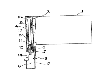
The catalytic combustion type heater 101 comprises a housing 103
having a combustion chamber 102 defined therein, a fuel injection nozzle 104
fluid-connected with a fuel source and disposed in the combustion chamber 102,
an
ignitor including an ignition terminal 105 disposed in the combustion chamber
102 for
igniting fuel supplied into the combustion chamber 102, a flexible air intake
tube 106
for introducing air to a position adjacent the fuel injection nozzle 104 so as
to mix with
the fuel injected from the fuel injection nozzle 104, and a flexible exhaust
tube 107
for discharging an exhaust gas from the combustion chamber 102 to the outside.
The
fuel source comprises a container receptacle including the sluice valve 30 and
the
sluice knob 29 as shown in Fig. 9 and is so designed that when a pressurized
fuel
container filled with butane in a liquid phase is loaded in the container
receptacle and
the sluice knob 29 is subsequently manipulated, the fuel can be supplied from
the
fuel injection nozzle 104 through a flexible fuel supply tube.
-30-
CA 02208973 1999-OS-13
When fuel is supplied to the nozzle 104 in the manner described above,
the fuel flowing through an ejector 109 is mixed with air introduced through
the air
intake tube 106 to form an air-fuel mixture which is subsequently ignited by a
spark
discharge emitted from the ignition terminal 105. A catalyst 110 is disposed
between
the combustion chamber 102 and the nozzle 104 to facilitate a catalytic
combustion
of the air-fuel mixture. The exhaust gas formed as a result of the combustion
is
discharged to the outside through the flexible exhaust tube 107.
The housing 103 is heated by the effect of combustion within the
combustion chamber 102. To facilitate heat radiation therefrom the housing 103
is
made of a metallic material having a high thermal conductivity. Housing 103
further
includes a plurality of heat radiating fins 111 extending laterally and
outwardly
therefrom.
In accordance with the thirteenth embodiment of the present invention,
the catalytic combustion type heater 101 is fitted to a portion of the inner
back of the
piece of clothing 71 which is generally aligned with a lower region of the
spine of the
wearer. As a result, the fuel supply tube leading to the nozzle 104, the air
intake tube
106, the exhaust tube 107 and electric lines of the ignitor connected with the
ignition
terminal 103 are preferably made of a material having a relatively high
flexibility so
that they will not constitute an obstruction to free movement of the wearer.
It is to be
noted that the fuel source including the fuel container and a battery forming
an
electric power source for the ignitor may be accommodated within a pocket of
the
piece of clothing 71. Respective free open ends of the air intake and exhaust
tubes
106 and 107 are communicated with the outside through a mesh fabric stitched
to an
appropriate portion of the piece of clothing 71.
-31-
CA 02208973 1999-12-13
Reference numeral 112 represents a temperature sensor substantially
identical in structure and function with the temperature sensor 84 shown in
Fig. 20. This
temperature sensor 112 is preferably employed in the form of a thermistor.
The catalytic combustion type heater 101 of the type discussed above is
fitted firmly to a heat insulating band 113 made of, for example, felt as
shown in Fig. 27.
In order for the heat transmitted from the housing 103 to the radiating fins
111 to
uniformly warm a substantial area of the wearer's back, a band-shaped heat
conducting
member 114 is preferably interposed between the heater 101 and the heat
insulating
band 114. This band-shaped heat conducting member 114 may be a heat conducting
textile fabric which may be, for example, a woven fabric woven by the use of
aluminum-
plated glass yarns having a high heat diffusion property, a woven fabric
containing
carbon fibers, a woven fabric containing natural or synthetic yarns formed
with a layer
of metallic particles dispersed in a flexible resinous binder, a woven fabric
made up of
metallic fibers, or a woven fabric woven by the use of metallic fibers and
fibers other
than the metallic fibers, as in the case with the heating sheet discussed
hereinbefore.
Preferably, the heat conducting textile fabric is in the form of a woven
fabric made up
of one of polyester and copper threads forming a weft and the other of the
polyester
and copper threads forming a warp.
The heat insulating band 113 having the heater 101 fitted thereto is
releasably fitted to an inner back of the piece of clothing 71. For this
purpose, as a
releasable fitting means, a flexible planar fastener, such as "Velcro~" may be
stitched
to one of opposite surfaces of the heat insulating band 113 opposite to the
heater 101,
or a zipper may be stitched along a peripheral edge of the heat insulating
band 113.
Alternatively, the heat insulating band 113 may be stitched to the piece of
-32-
CA 02208973 1999-OS-13
clothing 71, in which case only the heater 101 may be separable from the heat
insulating band 113.
Thus, it is clear that even the thirteenth embodiment of the present
invention as shown in Figs. 27 to 29, can provide comfortable heating as is
the case
with any one of the foregoing embodiments of the present invention.
It is to be noted that in the practice of the thirteenth embodiment of the
present invention the piece of clothing 71 may be a jacket, a coat, an
overcoat or the
like. It is also to be noted that not only may the piece of clothing be
manufactured
with the heater-incorporated therein, the heat insulating band with the heater
secured
thereto can be fitted to any existing piece of clothing and in such case, an
extra
pocket having its mouth adapted to be closed by a zipper or a flexible planar
fastener
may be formed in an inner layer of the clothing for accommodating the heater
together with the heat insulating band.
-33-