Language selection

Search

Patent 2209429 Summary

Third-party information liability

Some of the information on this Web page has been provided by external sources. The Government of Canada is not responsible for the accuracy, reliability or currency of the information supplied by external sources. Users wishing to rely upon this information should consult directly with the source of the information. Content provided by external sources is not subject to official languages, privacy and accessibility requirements.

Claims and Abstract availability

Any discrepancies in the text and image of the Claims and Abstract are due to differing posting times. Text of the Claims and Abstract are posted:

  • At the time the application is open to public inspection;
  • At the time of issue of the patent (grant).
(12) Patent: (11) CA 2209429
(54) English Title: VEHICLE CAB VENTILATING SYSTEM
(54) French Title: SYSTEME DE VENTILATION POUR L'ABITACLE D'UN VEHICULE
Status: Deemed expired
Bibliographic Data
(51) International Patent Classification (IPC):
  • B60H 3/06 (2006.01)
  • B60H 1/24 (2006.01)
(72) Inventors :
  • TEICH, MICHAEL (Germany)
  • WAGNER, JUERGEN (Germany)
(73) Owners :
  • DEERE & COMPANY (United States of America)
(71) Applicants :
  • DEERE & COMPANY (United States of America)
(74) Agent: BORDEN LADNER GERVAIS LLP
(74) Associate agent:
(45) Issued: 2000-10-31
(22) Filed Date: 1997-07-04
(41) Open to Public Inspection: 1998-01-12
Examination requested: 1997-07-04
Availability of licence: N/A
(25) Language of filing: English

Patent Cooperation Treaty (PCT): No

(30) Application Priority Data:
Application No. Country/Territory Date
196 28 089.3 Germany 1996-07-12

Abstracts

English Abstract


A ventilating system for a vehicle cab includes a blower which draws fresh air
from the
exterior of the cab into the interior of the cab. A filter housing is inserted
generally
transverse to the direction of air flow through a service opening in the
ventilating system into
the channel through which the fresh air flows. The filter housing encloses a
fresh air filter.
The blower also draws recirculating air from the interior of the cab through a
recirculating air
intake opening and blows it back through a recirculating air filter into the
cab through an
outlet opening. The recirculating air filter is also mounted in the filter
housing. A filter insert
includes a filter housing which contains the fresh air filter and the
recirculating air filter,
which are adjacent each other on either side of a separating wall, fresh air
and recirculating
air are separately filtered.


Claims

Note: Claims are shown in the official language in which they were submitted.


The embodiments of the invention in which an exclusive property or privilege
is
claimed are defined as follows:
1. A vehicle cab ventilating system comprising:
a main housing defining a fresh air intake opening, an outlet opening and a
service
opening;
a filter housing for removable insertion into the main housing through the
service
opening, the filter housing defining a recirculating air intake opening;
a fresh air filter mounted in the filter housing so that the fresh air flows
from the fresh
air intake through the fresh air filter;
a recirculating air filter mounted in the filter housing so that the
recirculated air flows
from the recirculating air intake opening through the fresh air filter, the
fresh air filter (28) and
the recirculating air filter (38) being arranged in parallel with respect to
air flowing therethrough;
a separating wall mounted in the filter housing and positioned between the
fresh air
filter (28) and the recirculating air filter (38) so that fresh air and
recirculating air are filtered
separately; and
a blower in the main housing for drawing air from the fresh air and
recirculating air
intake openings through the respective fresh air and recirculating air filters
and to the outlet
opening.
2. The ventilating system of claim 1, further comprising:
means for combining and mixing the air flowing through the fresh air and
recirculating air filters downstream of the filters.
3. The ventilating system of claim 1, further comprising:
adjusting devices for selective throttling of the air flows.
4. The ventilating system of claim 1, wherein:
the filter housing can be inserted generally upwardly into the air flow
through a
downwardly opening service opening formed by the main housing.
5. The ventilating system of claim 1, wherein:
the fresh air filter is arranged in an upper part of the filter housing and
the
recirculating air filter is arranged in a lower part of the filter housing
6. The ventilating system of claim 1, wherein:
the recirculating air intake opening is formed by the filter housing.
7. The ventilating system of claim 1, wherein:
the filter housing is downstream of an evaporator/heater unit and is upstream
of the


blower.
8. The ventilating system of claim 1, wherein by:
the blower has an outlet having outlet jets.
9. The ventilating system of claim 8, wherein:
the outlet jets are eccentrically supported in bearings and have inclined
ribs.
10. The ventilating system of claim 1, further comprising:
a pair of knurled-head screws for securing the filter housing in its installed
position.
11. The ventilating system of claim 1, wherein:
the filter housing has flanges which are received by guide tracks attached to
the
main housing.
12. The ventilating system of claim 1, wherein:
the fresh air filter and/or the recirculating air filter are secured in the
filter housing by
means of wing-head screws.
13. The ventilating system of claim 1, wherein:
the fresh air filter and the recirculating air filter are positioned adjacent
each other on
opposite sides of a separating wall.
14. The ventilating system of claim 13, wherein:
the filter housing includes guidance devices for guiding insertion of the
filter housing
through the service opening.
15. The ventilating system of claim 14, wherein:
the filter housing forms the recirculating air intake opening.

Description

Note: Descriptions are shown in the official language in which they were submitted.

Sorry, the description for patent document number 2209429 was not found. Text is not available for all patent documents. The current dates of coverage are on the Currency of Information  page
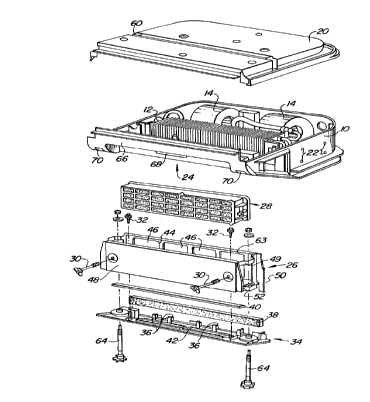
Representative Drawing
A single figure which represents the drawing illustrating the invention.
Administrative Status

For a clearer understanding of the status of the application/patent presented on this page, the site Disclaimer , as well as the definitions for Patent , Administrative Status , Maintenance Fee  and Payment History  should be consulted.

Administrative Status

Title Date
Forecasted Issue Date 2000-10-31
(22) Filed 1997-07-04
Examination Requested 1997-07-04
(41) Open to Public Inspection 1998-01-12
(45) Issued 2000-10-31
Deemed Expired 2005-07-04

Abandonment History

There is no abandonment history.

Payment History

Fee Type Anniversary Year Due Date Amount Paid Paid Date
Request for Examination $400.00 1997-07-04
Registration of a document - section 124 $100.00 1997-07-04
Application Fee $300.00 1997-07-04
Maintenance Fee - Application - New Act 2 1999-07-05 $100.00 1999-07-02
Maintenance Fee - Application - New Act 3 2000-07-04 $100.00 2000-06-30
Final Fee $300.00 2000-08-09
Maintenance Fee - Patent - New Act 4 2001-07-04 $100.00 2001-07-03
Maintenance Fee - Patent - New Act 5 2002-07-04 $150.00 2002-07-03
Maintenance Fee - Patent - New Act 6 2003-07-04 $150.00 2003-07-03
Owners on Record

Note: Records showing the ownership history in alphabetical order.

Current Owners on Record
DEERE & COMPANY
Past Owners on Record
TEICH, MICHAEL
WAGNER, JUERGEN
Past Owners that do not appear in the "Owners on Record" listing will appear in other documentation within the application.
Documents

To view selected files, please enter reCAPTCHA code :


To view images, click a link in the Document Description column. To download the documents, select one or more checkboxes in the first column and then click the "Download Selected in PDF format (Zip Archive)" or the "Download Selected as Single PDF" button.

List of published and non-published patent-specific documents on the CPD .

If you have any difficulty accessing content, you can call the Client Service Centre at 1-866-997-1936 or send them an e-mail at CIPO Client Service Centre.


Document
Description 
Date
(yyyy-mm-dd) 
Number of pages   Size of Image (KB) 
Cover Page 2000-10-04 1 57
Representative Drawing 2000-10-04 1 28
Abstract 1997-07-04 1 20
Description 1997-07-04 6 387
Claims 1997-07-04 2 63
Drawings 1997-07-04 3 126
Representative Drawing 1999-10-01 1 18
Claims 1999-12-21 2 72
Cover Page 1999-10-01 1 47
Correspondence 2000-08-09 1 28
Prosecution-Amendment 1999-11-09 2 3
Prosecution-Amendment 1999-12-21 4 123
Assignment 1997-07-04 4 180
Prosecution-Amendment 1999-12-23 1 23