Language selection

Search

Patent 2209456 Summary

Third-party information liability

Some of the information on this Web page has been provided by external sources. The Government of Canada is not responsible for the accuracy, reliability or currency of the information supplied by external sources. Users wishing to rely upon this information should consult directly with the source of the information. Content provided by external sources is not subject to official languages, privacy and accessibility requirements.

Claims and Abstract availability

Any discrepancies in the text and image of the Claims and Abstract are due to differing posting times. Text of the Claims and Abstract are posted:

  • At the time the application is open to public inspection;
  • At the time of issue of the patent (grant).
(12) Patent Application: (11) CA 2209456
(54) English Title: SETTING TOOL FOR NAILS OR THE LIKE
(54) French Title: INSTRUMENT DE MISE EN PLACE DE CLOUS OU ARTICLES SIMILAIRES
Status: Dead
Bibliographic Data
(51) International Patent Classification (IPC):
  • B25C 9/00 (2006.01)
  • A61B 17/068 (2006.01)
  • A61B 17/92 (2006.01)
(72) Inventors :
  • KIRSCH, AXEL (Germany)
  • DURR, WALTER (Germany)
(73) Owners :
  • KIRSCH, AXEL (Germany)
(71) Applicants :
  • ALTATEC MEDIZINTECHNISCHE ELEMENTE GMBH & CO. KG (Germany)
  • IMZ - FERTIGUNGS- UND VERTRIEBSGESELLSCHAFT FUR DENTALE TECHNOLOGIE MBH (Germany)
  • KIRSCH, AXEL (Germany)
(74) Agent: ROBIC
(74) Associate agent:
(45) Issued:
(22) Filed Date: 1997-07-02
(41) Open to Public Inspection: 1998-01-03
Examination requested: 1998-01-08
Availability of licence: N/A
(25) Language of filing: English

Patent Cooperation Treaty (PCT): No

(30) Application Priority Data:
Application No. Country/Territory Date
196 26 892.3 Germany 1996-07-03

Abstracts

English Abstract


A setting tool for nails, with a hollow-cylindrical grip sleeve open at both
ends, whereby a first hollow section is connected to a second hollow section
by a
through opening into which the following components are placed: a ram at which
a nail is to be directly or indirectly releasably held and extending from the
grip
sleeve, a pin that is surrounded by a coil spring whose axis is offset out of
the axis
of the grip sleeve and that has the seating section of a first pin segment
lying
against the ram, and whereby a centering surface is provided in the transition
region from the first pin segment to a second pin segment, a coupling piece
whose
side facing toward the pin is provided with a blind hole into which the second
pin
segment can at least partially immerse and whose diameter is smaller than the
diameter of the through opening, a second coil spring and an adjustment device
that is adjustably inserted into the second open end of the grip sleeve,
whereby the
second coil spring lies, on the one hand, against the coupling piece and, on
the
other hand, against the adjustment device, and whereby the ram and the pin
together with the coil spring surrounding it are at least partially
accommodated in
the first hollow section and the coupling piece, the second coil spring and
the
adjustment device are accommodated in the second hollow section.


Claims

Note: Claims are shown in the official language in which they were submitted.


Claims


1. Setting tool for nails, comprising
- a hollow-cylindrical grip sleeve (10) open at both ends (12, 24), whereby a
first hollow section (16) is connected to a second hollow section (20) by a
through opening (18) into which the following components are placed:
- a ram (40; 140) at which a nail (100) is to be directly or indirectly
releasably held and extending from the grip sleeve (10),
- a pin (50; 150) that is surrounded by a coil spring (70) whose axis is
offset out of the axis of the grip sleeve (10) and that has the seating
section of a first pin segment (54; 154) lying against the ram (10;
140), and whereby a centering surface {56; 156) is provided in the
transition region from the first pin segment (54; 154) to a second pin
segment (58; 158),
- a cylindrical coupling piece (60) whose side facing toward the pin
(50; 150) is provided with a blind hole (62) into which the second
pin segment (58; 158) can at least partially immerse and whose
diameter is smaller than the diameter of the through opening (18),
- a second coil spring (80),
- and an adjustment device (90) that is adjustably inserted into the
second open end (24) of the grip sleeve (10),
whereby the second coil spring (80) lies, on the one hand, against the
coupling piece (60) and, on the other hand, against the adjustment device
(90), and whereby the ram (40; 140) and the pin (50; 150) together with the
coil spring (70) surrounding it are at least partially accommodated in the
first hollow section (10) and the coupling piece (60), the second coil spring
(80) and the adjustment device (90) are accommodated in the second hollow
section (20).


7


2. Setting tool according to claim 1, characterized is that the seating
section
(52) of the pin (50) at the ram (40) and/or the seating section (460 of the
ram (40) at
the pin (50) axe arced at their contacting region.

3. Setting tool according to claim 1, characterized in that the free end (42)
of
the ram (40) is fashioned as a holder (42, 44) for the head of a nail (100).

4. Setting tool according to claim 1, characterized in that the ram (140) and
the pin (150) are hollow-cylindrically fashioned, whereby an inside pin (157
whose
length is greater than the length of the pin is accommodated in the pin (150),
said
inside pin (157) acting directly or indirectly on a nail holder (11) that is
inserted
into the ram (140).

5. Setting tool according to claim 4, characterized in that a coupling pin
(146) is accommodated in the ram (140).

6. Setting tool according to claim 4 or 5, characterized in that the ram (140}
comprises viewing windows (148).

7. Setting tool according to one of the claims 4 through 6, characterized in
that the ram (140) comprises a catch means (149) for engagement with the nail
holder (110).

8. Setting tool according to one of the claims 1 through 7, characterized in
that the adjustment device (90) is an adjustment screw whose threaded section
(92,
94) engages into an inside threaad (22) provided in the grip sleeve (10).


8


Lisp of Reference Characters

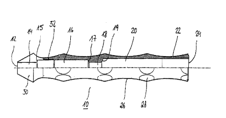
grip sleeve
12 first open end
14 opening section
conical section
16 first hollow section
17 conical surface
18 through opening
19 conical surface
second hollow section
22 inside thread
24 second open end
26 holding depressions
28 finger depressions
front part of the grip sleeve 10
32 thread
ram
42 bevel
43 cross-recessed gap
44 seating shoulder
gripper jaw
46 seating section
48 shaft
pin
52 seating section
54 first pin section
56 centering surface
58 second pin section
coupling piece
62 blind hole
coil spring
coil spring
adjustment screw
92 shaft
94 thread
96 head
98 gripping rifling
100 nail
110 nail holder
112 catch notch
113 gripper jaw

9


114 seating shoulder
140 ram
142 seating section
143 recess
144 cylinder wall
145 free end section of the ram
146 coupling pin
147 head
148 viewing window
149 catch rib
150 pin
152 seating section
153 seating edge
154 first pin section
156 centering surface
157 inside pin
158 second pin section
159 head of the inside pin


Description

Note: Descriptions are shown in the official language in which they were submitted.

Sorry, the description for patent document number 2209456 was not found. Text is not available for all patent documents. The current dates of coverage are on the Currency of Information  page

Representative Drawing
A single figure which represents the drawing illustrating the invention.
Administrative Status

For a clearer understanding of the status of the application/patent presented on this page, the site Disclaimer , as well as the definitions for Patent , Administrative Status , Maintenance Fee  and Payment History  should be consulted.

Administrative Status

Title Date
Forecasted Issue Date Unavailable
(22) Filed 1997-07-02
(41) Open to Public Inspection 1998-01-03
Examination Requested 1998-01-08
Dead Application 2000-07-04

Abandonment History

Abandonment Date Reason Reinstatement Date
1999-07-02 FAILURE TO PAY APPLICATION MAINTENANCE FEE

Payment History

Fee Type Anniversary Year Due Date Amount Paid Paid Date
Application Fee $300.00 1997-07-02
Registration of a document - section 124 $100.00 1997-10-16
Request for Examination $400.00 1998-01-08
Owners on Record

Note: Records showing the ownership history in alphabetical order.

Current Owners on Record
KIRSCH, AXEL
Past Owners on Record
ALTATEC MEDIZINTECHNISCHE ELEMENTE GMBH & CO. KG
DURR, WALTER
IMZ - FERTIGUNGS- UND VERTRIEBSGESELLSCHAFT FUR DENTALE TECHNOLOGIE MBH
KIRSCH, AXEL
Past Owners that do not appear in the "Owners on Record" listing will appear in other documentation within the application.
Documents

To view selected files, please enter reCAPTCHA code :


To view images, click a link in the Document Description column. To download the documents, select one or more checkboxes in the first column and then click the "Download Selected in PDF format (Zip Archive)" or the "Download Selected as Single PDF" button.

List of published and non-published patent-specific documents on the CPD .

If you have any difficulty accessing content, you can call the Client Service Centre at 1-866-997-1936 or send them an e-mail at CIPO Client Service Centre.


Document
Description 
Date
(yyyy-mm-dd) 
Number of pages   Size of Image (KB) 
Representative Drawing 1999-10-04 1 8
Abstract 1997-07-02 1 32
Description 1997-07-02 6 270
Drawings 1997-07-02 3 44
Claims 1997-07-02 4 98
Cover Page 1999-10-04 1 46
Prosecution-Amendment 1998-01-08 1 39
Assignment 1997-07-02 3 95
Correspondence 1997-09-11 1 28
Assignment 1997-10-16 10 270