Note: Descriptions are shown in the official language in which they were submitted.
CA 02209~03 1997-07-03
,
REMOVABLE HEADREST FOR CHAIRS
BACKGROUND OF THE I~v~NllON
1. FIELD OF THE INVENTION
The present invention relates generally to
furnishings, seating, and accessories therefor, and
more particularly to various embodiments of a
removable, portable headrest which may be temporarily
installed upon the back of a chair or the like for the
support of a seated person's head. The device
generally comprises a pocket which fits over the upper
portion of the back of the chair, with a vertically
adjustable headrest secured thereto. The device may
be placed upon the back of a chair as desired, with
the headrest being adjusted for optimum comfort. The
device may be removed for storage or placement on
another chair, as desired. The present removable
headrest is particularly well suited for use with lawn
chairs, deck chairs, and the like, but may be adapted
for use with other types of chairs as well.
2. DESCRIPTION OF THE PRIOR ART
Lightweight, portable, and/or casual seating, such
as folding lawn chairs, deck chairs, and the like,
have been known for some time. One feature which is
almost universal with such seating is the lack of any
head support, due to this type of seating needing to
be relatively simple, lightweight, and to fold to a
compact size.
Accordingly, such seating generally provides only
the bare minimum of comfort or convenience features,
with no real attempt at padding or upholstery (other
than perhaps some form of webbing), and often not even
having arm rests, in the case of most folding metal
chairs. While chaise lounges and the like may provide
CA 02209~03 1997-07-03
sufficient support for the head, such elongate
recliners do not provide upright, chair-like seating.
Other heavier upholstered chairs, as often found in
the living areas of residences and the like, often
have a seat back which is sufficiently high as to
provide support for the head, but such seating is not
particularly portable, nor is any headrest portion
removable from such chairs.
Accordingly, a need will be seen for a removable,
portable headrest for chairs such as lawn chairs, deck
chairs, folding chairs, and other lightweight and
portable seating. While the present headrest is
adapted to be particularly suitable for such seating,
it should be noted that it is also applicable to other
types of seating as well. The device generally
comprises a pocket which fits over the upper portion
of the seat back, with a vertically adjustable
headrest extending upwardly therefrom. The seat back
pocket is preferably formed of plastic material, with
the front portion thereof being relatively flexible
compared to the opposite back portion, for comfort.
The headrest may be supported by a single central arm,
or two opposite lateral arms, as desired. A
discussion of the prior art of which the present
inventor is aware, and its distinctions from the
present invention, is presented immediately below.
U. S. Patent No. 162,784 issued on May 4, 1875 to
Willard M. White describes a Head-Rest having a screw
actuated clamp at the base thereof, for removable
attachment to a chair or the like. The vertical
adjustment for the headrest portion is limited, as the
lower end of the arm holding the headrest fits into a
pocket in the front portion of the removable base,
rather than extending downwardly through the base.
The present headrest support arm provides considerably
more adjustment, as it passes completely through
passages or channels in the back or sides of the
CA 02209~03 1997-07-03
pocket portion which fits over the back of the chair,
and thus is not limited by a fitting residing on the
front surface of the chair back, as in the case of the
White device.
U. S. Patent No. 280,078 issued on June 26, 1883 to
George Popplewell describes a Head Rest providing for
removable attachment to the back of a railroad
passenger car seat or the like. The device comprises
a spaced apart pair of generally U-shaped members
which grasp the upper edge of the seat back, with each
having a threaded rod extending upwardly therefrom.
An adjustable headrest is installed between the two
threaded rods. At least one embodiment of the present
invention may include a pair of spaced apart headrest
supports with the headrest being instalIed
therebetween, but Popplewell does not disclose any
form of pocket which may be installed over the upper
portion of the seat back, as provided by the present
invention. The separate seat back grasping components
would produce discomfort for the upper back of a
seated person, unlike the smooth, continuous pocket of
the present device.
U. S. Patent No. 2,081,333 issued on May 25, 1937 to
Myrl P. Hoover describes an Adjustable Chair having a
high back with a vertically adjustable headrest
movably secured thereto. The headrest slides upwardly
and downwardly on a pair of spaced apart straps which
are immovably affixed to the chair back, which
principle of operation is opposite that of the present
headrest which in each embodiment is at least
vertically (or immovably) affixed to the support
arm(s), with the arm(s) being adjustable relative to
the seat back attachment pocket and thus to the chair
itself. Moreover, the Hoover headrest may be
adjustable, but it is not removable, as provided by
the present headrest.
CA 02209~03 1997-07-03
U. S. Patent No. 4,498,704 issued on February 12,
1985 to Joseph R. Hildreth describes a Headrest For
Chair With Soft Backrest, comprising a pair of
generally U-shaped flat members which are secured
closely together to sandwich the flexible backrest
member of a wheelchair or the like, therebetween. One
of the U-shaped members is vertically adjustable
relative to the other, to provide adjustment for a
headrest affixed to the second U-shaped member.
Again, the positioning of the two upwardly extending
metal arms of the forwardly disposed U-shape member to
reside against the back of the seated person, would
create some discomfort even though the support members
are relatively thin. The present invention provides
an attachment member comprising a pocket which
completely covers the upper portion of the chair back,
thus providing a uniform surface for the back of a
seated person to rest against.
U. S. Patent No. 4,989,836 issued on February 5,
1991 to E. W. Hudson III et al. describes a Detachable
Wheelchair Headrest, comprising a pair of spaced apart
generally vertical arms having a flexible headrest
secured between the two arms. The two arms are
clamped to the two tubular upright members of the seat
back frame for the chair, rather than to a pocket
which fits over the upper back of the chair, as in the
present invention. (Such a pocket could not be used
with a wheelchair, due to the rearwardly extending
handgrips for the chair.) Hudson, III et al. describe
the adjustment of the headrest band by turning one of
the support members to wrap the band around the
support, but this would result in an asymmetric
configuration, unless sufficient slack existed to turn
each member equally. This is critical in the Hudson,
III et al. headrest, as they provide additional
lateral head support means on the headrest band, which
means must be symmetrically positioned. Moreover, the
CA 02209~03 1997-07-03
Hudson, III et al. headrest is not easily removable
from its supports, while the present headrest is.
U. S. Patent No. 5,356,201 issued on October 18,
1994 to Jerome Olson describes a Canoe Backrest
secured to a pair of vertically adjustable tubes, each
of which extends upwardly from a mounting bracket.
The brackets are bolted to the seat bottom, unlike the
present pocket arrangement which slips over the seat
back and is thus easily installable and removable
without modification to the chair. The Olson backrest
cannot be positioned sufficiently high to provide a
headrest, as the length of the support arms would
penetrate the bottom of the boat when retracted.
U. S. Patent No. 5,475,882 issued on December 19,
1995 to Joel L. Sereboff describes a Gel Filled
Deformable Cushion And Composition Contained Therein.
Sereboff does not disclose any means of mounting or
attaching his cushion to another device, which feature
is a critical part of a chair attachable headrest.
The present removable headrest invention may make use
of a gel filled cushion, but also provides for the
attachment of such a cushion to a supporting structure
which is in turn removably attachable to a chair or
the like.
U. S. Patent No. D-361,683 issued on August 29, 1995
to Darrol L. Juhl illustrates a design for a Removable
Lawn Chair Headrest. The design appears to disclose
a pair of split cylindrical upright components which
slip downwardly over each of the chair back uprights,
and which have a headrest extending thereacross. A
thicker component is secured behind the headrest by a
pair of lateral rear straps extending between the two
uprights. A crossmember is also provided between the
uprights. No pocket is shown which may be removably
secured over the upper portion of the seat back, as in
the present invention, nor is any form of adjustment
apparent for the headrest.
CA 02209~03 l997-07-03
German Patent Publication No. 669,879 published on
January 6, 1939 illustrates a headrest which
apparently secures to the back of a chair by means of
a lateral strap therearound. Lateral retainers or
clips secure to the upright members of the chair back.
No pocket is disclosed which fits completely over the
uppermost portion of the chair back, as provided by
the present invention.
German Patent Publication No. 2, 419,483 published on
November 13, 1975 illustrates a chair having an
adjustable headrest affixed thereto. The headrest is
supported by a pair of spaced apart support arms, and
is vertically adjustable thereon. This is opposite
the present configuration, wherein the headrest is
affixed to the support arms and is not vertically
adjustable relative to the arms, but rather the arms
are vertically adjustable relative to the chair
attachment pocket. The German ' 483 chair is specially
constructed to accept the headrest portion, unlike the
present invention comprising only a headrest assembly
which is removably installable to any suitable
unmodified chair. Thus, no removable pocket providing
for the removable installation of the headrest to the
upper portion of the chair back, is disclosed in the
German ' 483 patent.
Finally, British Patent Publication No. 1,378,430
published on December 27, 1974 describes Head Rests
For Seats comprising a pair of spaced apart generally
vertical headrest support members which are
permanently and immovably secured to the back of the
seat. The headrest is adjustably movable on the two
support members, rather than being vertically affixed
to the support members with the support members being
adjustable relative to the seat back, as in the
present invention. No removably installable pocket
for the upper portion of the seat back is disclosed in
.
CA 02209~03 1997-07-03
the British patent, as provided by the present
invention.
None of the above inventions and patents, taken
singly or in combination, is seen to describe the
instant invention as claimed.
SUMMARY OF THE lNv~NllON
Accordingly, it is a principal object of the
invention to provide an improved removable headrest
for chairs, comprising a pocket adapted to fit over
the upper portion of the back of a chair with headrest
support arm means adjustably installed therein, with
the headrest support arm means including a headrest
affixed to the upper end thereof.
It is another object of the invention to provide an
improved removable headrest for chairs which headrest
support arm means may comprise a single support arm
adjustably lockable in position to the back of the
pocket portion of the device, or which may
alternatively comprise two support arms with each of
the arms being adjustably lockable to one of the left
and right edges of the pocket portion, or which may
include support arm attachment means to the pocket
portion, comprising three sets of attachment means
disposed along the left edge, right edge, and rear
center of the pocket portion of the device.
An additional object of the invention is to provide
an improved removable headrest for chairs which
support arm locking means may comprise a threaded bolt
passing through the support arm, or which
alternatively may be an over center cam locking
device.
It is an object of the invention to provide improved
elements and arrangements thereof in an apparatus for
the purposes described which is inexpensive,
dependable and fully effective in accomplishing its
intended purposes.
CA 02209~03 1997-07-03
These and other objects of the present invention
will become readily apparent upon further review of
the following specification and drawings.
BRIEF DESCRIPTION OF THE DRAWINGS
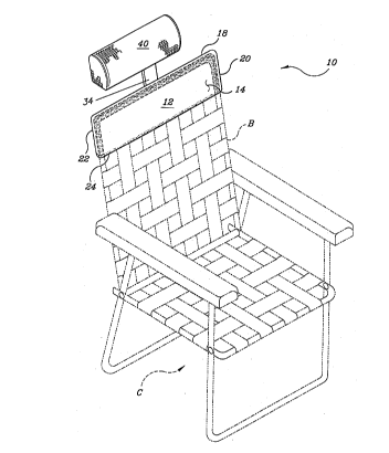
Figure 1 is a perspective view of a first embodiment
of the present removable headrest for chairs, showing
the headrest removably installed on the upper back
portion of a lawn chair.
Figure 2 iS a rear perspective view of the removable
headrest of figure 1, showing further details.
Figure 3 iS a side elevation view in section of an
alternative embodiment of the present headrest,
showing further details.
Figure 4 is a rear perspective view of another
alternative embodiment of the present headrest,
showing details thereof.
Figure 5 iS a fragmented perspective view showing
details of an alternative support arm attachment means
to the pocket portion.
Figure 6 is a rear perspective view showing another
alternative embodiment, including both a single
central support arm and two laterally disposed support
arms in a single device.
Figure 7 is a side elevation view in section of an
alternative locking means for the headrest support arm
of the present invention.
Similar reference characters denote corresponding
features consistently throughout the attached
drawings.
DETATT.Tm DESCRIPTION OF THE PREFERRED EMBODIMENTS
The present invention comprises various embodiments
of a removable headrest for chairs, a first embodiment
of which is shown in figures 1 and 2, and designated
with the reference numeral 10. The headrest 10
includes a pocket portion 12, which is adapted to fit
CA 02209~03 1997-07-03
closely over the upper portion of the back of a chair,
such as the back B of the lawn chair C shown in figure
1. (It will be seen that the present headrest 10,
and/or any of its embodiments, are also adaptable to
other types of chairs having back portions, as well.)
The pocket portion 12 has a front wall or surface 14,
an opposite rear surface or wall 16, a closed upper
edge 18, and opposite first and second lateral edges,
respectively 20 and 22. The lower edge 24 is open, to
provide access to the hollow interior 26.
The chair back pocket 12 may be formed using any of
a number of materials and methods, but is preferably
formed as a single, unitary component of semi-rigid
plastic material. It will be noted that both good
structural strength and compliance to the form of a
person using the present headrest 10 may be achieved
using such material. The rear wall 16 is formed to
have a relatively greater thickness 28 than the
relatively thin thickness 30 of the front wall 14,
thus providing good structural strength in the rear
wall 16 and also a flexible and compliant front wall
14, all in a single, unitary component.
The back 16 of the chair back pocket 12 includes a
generally vertically oriented headrest support arm
attachment channel formed thereon (preferably cast or
molded integrally with the remainder of the pocket
12), as shown in figure 2. The channel may comprise
a coaxial series of separate channel portions 32a,
32b, 32c, as shown in figure 2, or may alternatively
comprise a single, continuous channel length, as shown
in other embodiments. An elongate headrest support
arm 34 is removably and adjustably installed within
the channel 32a/b/c, with the support arm 34 having a
lower end 36 and an opposite upper end 38. The upper
end 38 of the headrest arm 34 includes some form of
headrest means, e. g., the padded or upholstered
resilient headrest pad 40 of figures 1 and 2, which
CA 02209~03 1997-07-03
may be permanently or removably secured to the upper
end 38 of the support arm 34.
It should be noted that the headrest pad 40 is not
adjustably positioned relative to the headrest support
arm 34 once it has been secured to the upper end 38 of
the arm 34. Rather, all adjustment is provided by
adjusting the position of the arm 34 within the
channel 32a/b/c. In the embodiment of figures 1 and
2, the headrest support arm 34 is provided with a
plurality of adjustment locking holes or passages 42
therein, and the channel portion 32b includes a
threaded passage or insert therethrough, similar to
that shown in the continuous channel embodiment of
figure 3. A cooperatingly threaded bolt having an
adjustment knob thereon, is threaded through the
passage and/or insert and a selected one of the
locking passages 42, to secure the support arm 34 as
desired.
A modified version of the above described headrest
is shown in figure 3 as headrest 10a. The primary
distinction between the headrests 10 of figures 1 and
2, and 10a of figure 3, is that the pocket 12a of
figure 3 has a headrest support arm attachment channel
32d which is formed as a single, unbroken length
extending substantially from the upper edge 18a to the
lower edge 24a of the pocket portion 12a, rather than
the plural channel segments 32a/b/c of the pocket 12
of figures 1 and 2. Other components, such as the
front wall 14a with its thin construction 30a, the
thickness 28a of the rear wall 16a, and space 26a
therebetween, are equivalent to similar features of
the headrest 10 of figures 1 and 2.
Also, the headrest pad 4Oa of figure 3 may include
a gel filled interior portion 41, in lieu of dry foam
or fiber cushion padding or fill. Such gels provide
better conformity to the back of the head of a user of
the present headrest 10a, and they may be chilled to
CA 02209~03 1997-07-03
11
provide benefits similar to an ice pack, if so
desired. Accordingly, the gel filled headrest pad 40a
is removable from the upper end 38a of the headrest
support arm 34a, by means of cooperating hook and loop
fastening material 43 or the like.
Figure 3 also discloses the threaded bolt 44 and
mating threaded insert 46 within the channel 32d,
which arrangement may be incorporated into any of the
embodiments of the present invention as desired, and
as indicated in the exterior view of figure 2. The
bolt 44 is operated by turning the knob 48 to remove
the bolt 44 from one of the headrest adjustment arm
passages 42a, or to tighten the bolt 44 to lock it
into one of the passages 42a, as desired.
Figure 4 discloses an alternative embodiment,
designated as headrest 50, in which the seat back
pocket 52 includes opposite first and second lateral
headrest support arm channels, respecti~ely 54 and 56,
which are formed integrally or otherwise affixed
respectively to the first and second lateral edges 58
and 60 of the pocket 52. It will be seen that this
configuration does not require a single, central
headrest support arm channel (although one may be
provided in addition to the two lateral channels, as
shown in the embodiment of figure 6 discussed further
below). Accordingly, while the seat back pocket
portion 52 is otherwise similar to the pockets 10 and
lOa discussed above, having an upper edge 62, an open
lower edge 64, a thin front wall or panel 66, and a
relatively thicker rear panel or wall 68 with a hollow
interior 70 therebetween, the rear wall 68 is devoid
of any headrest support arm attachment channel or
means.
The first and second headrest support arm channels
54 and 56 each include a headrest support arm
adjustably installed therein, respectively a first arm
72 and a second arm 74. Each of the arms 72/74
CA 02209~03 1997-07-03
includes a plurality of locking holes or passages 76,
with a locking bolt and insert mechanism, similar to
that shown in figure 3 and discussed further above,
being provided in each of the lateral channels 54 and
56. (It will be understood that while only a single
locking knob is shown in figure 4, that the headrest
assembly of figure 4 is substantially symmetrical and
includes identical locking mechanisms on each side.)
The upper ends of the headrest support arms 72 and
74, respectively 78 and 80, provide for the removable
and adjustable attachment of a headrest band 82
thereto. The headrest band 82 comprises an elongate
sheet of flexible, pliable vinyl, fabric, or other
suitable material, and includes a headrest support arm
sleeve 84 sewn or otherwise formed at a first end 86
thereof. This sleeve 84 is closed (stitched, etc.) at
the upper end 88 thereof, to preclude slippage of the
first end 86 of the band 82 downwardly along the first
headrest support arm 78. The opposite second end 90
of the headrest band 82 includes first and second
portions 92 and 94 of mating hook and loop fastening
material thereon, whereby the end 90 may be adjustably
wrapped about the upper end 80 of the second headrest
support arm 74 as desired, to provide the desired
tension or slack in the headrest band 82.
In figure 4, the two lateral channels 54 and 56 are
each shown as single, unbroken, elongate channels
extending substantially from the upper end 62 to the
lower end 64 of the seat back pocket portion 52.
However, it will be seen that the alternative channel
arrangement shown in figure 2, comprising a plurality
of coaxial channel segments, may be used in the
construction of plural channel headrest. Such a
configuration is shown in figure 5 along the first
edge 58a of a pocket 52a, having a plurality of
channel segments 54a, 54b, and 54c. The locking means
is disposed in the central channel segment 54b, to
CA 02209~03 l997-07-03
13
secure a first support arm 72a therein. Otherwise,
the construction of the alternative headrest
embodiment of figure 5 is identical to the embodiment
of figure 4.
Figure 6 discloses a further alternate embodiment,
wherein a user of the device may select the specific
type of headrest means (headrest pad or headrest band)
used with the headrest pocket. In figure 6, a
headrest 100 includes a seat back pocket 102 formed
generally similarly to the pocket portion 52 of figure
4, having a front wall 104, an opposite rear wall 106,
a closed upper edge 108, opposite closed first and
second lateral edges 110 and 112, and an open lower
edge 114 providing access to a hollow interior 116.
As in the other embodiments discussed further above,
the rear wall 106 may have a thickness 118 greater
than the thickness 120 of the front wall, in order to
provide good structural strength and still provide
compliance with the back of a person using the
headrest.
The seat back pocket 102 also includes opposite
first and second lateral headrest support arm
channels, respectively 122 and 124, along the
respective first and second lateral edges 110 and 112.
Each channel 122/124 has a headrest support arm,
respectively 126 and 128, adjustably installed
therein. These two arms 126/128 proyide for the
installation of a headrest band 130 thereon, similar
to the configuration of the headrest 50 of figure 4.
However, the rear wall 106 also includes a single
central headrest support arm channel 132 thereon, with
a single headrest support arm 134 adjustably installed
therein having a single headrest pad 136 installed on
its upper end 138. This embodiment allows a user of
the headrest 100 to select whichever type of headrest
he or she wishes to use. Other components (headrest
CA 02209~03 1997-07-03
14
arm locking means, etc.) are similar to those features
of other embodiments discussed above.
To this point, only one specific type of headrest
support arm locking means has been described, i. e.,
the threaded bolt and insert shown in detail in figure
3. However, other types of support arm locking means
may be used, which are adaptable to any of the
headrest embodiments described above. Figure 7
discloses one such means, providing for the adjustable
locking of a headrest support arm to the back of a
chair back pocket 140. The pocket 140 includes a
front wall 142, opposite rear wall 144, closed upper
edge 146, open lower edge 148, and a hollow interior
150, as in other chair back pocket embodiments
discussed above. A headrest support arm channel,
comprising channel segments 152a, 152b, and 152c,
holds a headrest support arm 154 adjustably therein.
The support arm 154 may be formed of metal (e. g.,
stainless steel), or may alternatively be formed of
plastic or other suitable material, as indicated by
the cross sectional marking of figure 7, and it will
be seen that the channel segments 152a/b/c may
alternatively comprise a single channel, as shown in
the embodiment of figure 3.
The locking means disposed in the central channel
segment 152b comprises an over center cam lever 156,
which rotates about a pivot pin 158 which is installed
laterally through the channel member 152b. The lever
156 includes a cam lobe 160 thereon, which passes over
center (i. e., slightly beyond a point directly below
the pivot pin 158) when the lever 156 is locked
downwardly against the channel 152b. The lobe 160
also bears tightly against the headrest support arm
154 in this locked position, precluding movement of
the arm relative to the headrest pocket 140.
(Clearances are exaggerated.)
CA 02209~03 1997-07-03
To adjust the support arm 154 within the channel
152a/b/c, the lever 156 is lifted to draw the cam lobe
160 back from its bearing position against the surface
of the support arm 154, as shown in broken lines in
figure 7. Thus, the headrest support arm 154 may be
adjusted to any of a practically infinite number of
positions as desired, and locked into position to fix
the position of the headrest relative to the chair
back pocket as desired.
In summary, the above described removable headrest
for chairs, in any of its embodiments, will be seen to
provide a most useful and desirable accessory for lawn
and garden furniture, as well as for virtually any
other type of folding or non-folding chair which does
not have a high back against which a seated person may
rest their head. The semi-rigid plastic form of the
chair back pocket provides the required structural
strength, while still providing comfort to a user by
means of the thin and flexible front wall or panel
thereof. It will be seen that the chair back pocket
may take on virtually any external appearance, as
shown by the various smoothly rounded and squared,
truncated shapes shown in the various drawing figures
of the present disclosure; other shapes may be
provided as desired. The chair back pocket may
provide for only a single resilient headrest pad
having a foam, fiber, or gel center, or may
alternatively provide two supports for a headrest band
spanning the two supports, or may even provide for
either alternative, depending upon the configuration
of the headrest support arm channels provided on the
chair back pocket. The various headrest support arms
described herein may be formed of a
durable, corrosion resistant metal (i. e., stainless
steel) for long life outdoors, or may alternatively be
formed of virtually any suitable material (aluminum,
plastic, etc.), depending upon the structural
CA 02209~03 1997-07-03
16
requirements and desired longevity as opposed to the
economics of construction of the present device.
Either finite or infinite adjustment may be provided,
depending upon the locking means provided to secure
the headrest support arm(s) in place relative to the
chair back pocket. The above described accessory
provides a most economical means to expand the comfort
provided by an otherwise ordinary chair.
It is to be understood that the present invention is
not limited to the sole embodiments described above,
but encompasses any and all embodiments within the
scope of the following claims.