Note: Descriptions are shown in the official language in which they were submitted.
CA 02209~34 l997-07-03
~ .
Prefilled syringe for medical use
The invention relates to a prefilled syringe for medical
use with a syringe barrel and a syringe piston in the barrel
actuated by a piston rod and also with a cannula attachment
mounted axially on the end of the syringe barrel adjacent to
the cannula and retained in the seat and gripping the end of
the syringe barrel adjacent to the cannula. The device also
has a plug coaxial with the cannula attachment and inserted in
the syringe barrel, with a collar of which the front side
o rests on the syringe barrel and the other side on a circular
shoulder of the cannula attachment and with a through-hole
along its axis.
An example of such a syringe is known from DE 41 27 650.
In this syringe a tip cap is mounted on the cannula attachment
with its front side sealing off the through-hole in the plug,
for which purpose the plug has an attachment penetrating the
cone of the cannula attachment. The medication in the
prefilled syringe is therefore sealed off through the sealing
surface between the tip cap and the attachment, which in
individual cases may not be adequate.
The purpose of the invention is therefore to design a
prefilled syringe of the type referred to above such that the
medication is enclosed in a sterile conditlon during storage
and comes into contact solely with the material of the syringe
barrel, the plug and the syringe piston, that is to say
preferably solely with rubber and glass.
This purpose is accomplished in accordance with the
invention by placing in the through-hole a membrane closing
it, opposite which there is at a short distance on the side
facing away from the syringe barrel at least one spike with
its tip pointing at the membrane.
The essential advantage of the invention is that the plug
is completely sealed off by the membrane in the through-hole
so that the medication does not come into contact with the pin
of the tip cap, which usually projects into the through-hole.
To open the membrane before injection takes place it is
sufficient to shift the syringe piston by means of the piston
rod slightly towards the end adjacent to the cannula, so that
CA 02209~34 l997-07-03
r
the interior pressure in the syringe barrel becomes high
enough for the membrane to be moved to the point of the spike
and pierced.
In order to make this opening of the membrane
reproducible a preferred embodiment of the invention provides
for the piston rod to have a short male thread projecting
radially over the piston shaft in the portion of the rod
adjoining the piston, and this male thread is matched by a
female thread on the end of the syringe barrel facing away
o from the cannula attachment or on the finger rest. The
positioning and the length of the male thread is selected to
ensure that the pressure building up inside the syringe barrel
is sufficient to move the membrane to the tip of the spike.
The threaded portion of the piston rod can then be released
from the female thread so that the user can move the piston
rod freely.
In another preferred embodiment of the invention, the
plug has a pocket-shaped recess on its side facing away from
the syringe barrel, into which a circular piece bearing the
spike is fitted. This circular piece can be made especially
of relatively rigid plastic material. It is useful for the
outer surface of the circular piece to have the shape of a
double cone which ensures that the piece will be automatically
retained in the recess. To facilitate assembly the surfaces
of the cone may preferably be tapered towards the front
surfaces of the circular piece.
It is also useful for the surface of the membrane which
faces the spike to lie flush with the bottom of the recess. In
this manner, the shortest distance between the membrane and
the spike is achieved.
In a further advantageous version of the invention, a
filter plate is placed in the through-hole on the side of the
spike facing away from the membrane. This filter plate serves
both to hold back solid particles which may occur in a liquid
medication and also, if necessary, pieces of the membrane
which may come loose when it is opened. The filter plate is
so positioned as to ensure, in the first place, that it cannot
CA 02209~34 l997-07-03
-- 3
be damaged during storage and when it is subject to changes of
pressure during transportation. In addition the filter plate
does not come in contact with the medication during storage
and is therefore kept dry for the whole of this time.
Furthermore the filter plate stays sterile as it is protected
on the one side from the membrane and is protected on the
other side by the tip cap. Positioning the filter plate
inside the circular piece has a further advantage in that the
patient does not see it. This does not arouse distrust in the
o medication on the part of the patient, in contrast to previous
practice which required an external filter to be mounted.
Moreover, if the presence of a filter plate is required in any
case, this feature makes it impossible to forget, through
inadvertence, to place the disk in position before the
injection.
It is also suggested that, as part of the invention, the
cannula attachment grips by means of a pocket-shaped connector
the end of the syringe barrel adjacent to the cannula which
has an outer collar.
If the syringe is designed, for example, as a two-chamber
syringe with the preparation in lyophilized form in the
chamber adjacent to the cannula and lyophilization taking
place in the syringe, it can be arranged as part of the
invention that a circular protrusion projecting radially
inwards is placed on the connector and that two circular
grooves are positioned one behind the other along the axis of
the outer collar of the syringe barrel, so that when the
circular protrusion engages in the first circular groove the
cannula attachment retains the plug in such a way as to form a
circular gap between the inner side of the outer collar and
the plug, and that when the circular protrusion engages in the
second circular groove the plug rests against the inner side
of the outer collar and acts as a seal. This makes it possible
first to produce lyophilization via the circular gap and then
to press the cannula attachment fully on to the syringe
barrel, causing the circular protrusion to shift from the
first to the second circular groove.
CA 02209~34 l997-07-03
To facilitate attachment of the connector it is
advantageous to provide the latter with several recesses
uniformly distributed over its circumference and having the
form of slits running along the axis as far as the free edge
of the connector. To prevent the attachment from working
loose it is recommended that the cannula attachment is secured
by a lock ring gripping the connector.
It is also useful for the cannula attachment to have a
cone closed by a tip cap for attaching the cannula.
o Lastly, it is advantageous, for the purpose of checking
whether the syringe is still in its original condition, if,
when the lock ring is pushed on to the connector, a safety cap
enclosing the cone for the cannula and the tip cap mounted on
it is attached via a connector strip designed as a rated
breaking point.
A preferred embodiment of the invention is described in
detail below with reference to the accompanying drawings, in
which:
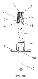
Figure 1 is an overall view of a preferred embodiment of
the syringe of the present invention;
Figure 2 is enlargement of the end of the syringe as in
Figure 1 adjacent to the cannula; and
Figure 3 shows the plug of the syringe still further
enlarged.
The syringe shown in the drawings is intended to be kept
prefilled and ready for use. In detail, the syringe consists
of a syringe barrel 1 and within the barrel a syringe piston 3
actuated by a piston rod 2. On the end of the syringe barrel
1 adjacent to the cannula a cannula attachment 4 retained in
the seat is mounted axially and grips the end of the syringe
cylinder 1 adjacent to the cannula. In addition, a plug 5 is
inserted in the syringe barrel 1, positioned coaxially with
the cannula attachment 4 and having a collar 5.1 with its
front side against the syringe barrel 1 and its other side
against a circular shoulder of the cannula attachment 4. This
plug 5 has a through-hole 6 along its axis.
In the through-hole 6 is placed an elastic membrane 7
CA 02209~34 l997-07-03
r
which closes it and ensures that the medication does not come
in contact with, for example, the pin 8.1 of the tip cap 8
which lies behind it. The plug 5 forms a complete seal
against the cannula attachment.
On the side facing away from the syringe barrel 1 there
is opposite to the membrane 7 and at a short distance from it
a spike 9 which serves to open the membrane 7 before the
syringe is put to use. Before use the syringe cylinder 3 is
pushed to the end of the syringe barrel 1 adjacent to the
0 cannula, causing the pressure inside the syringe barrel 1 to
rise. This causes the membrane 7 to bulge out towards the
spike 9 until it touches the tip of the spike 9 and is pierced
by it. This usually produces a tear over the entire cross-
section of the through-hole 6. The syringe can then be vented
and injection can proceed immediately.
To ensure that pressure inside the syringe barrel 1 is
under control as it increases the piston rod 2 has on the
portion of it adjoining the piston 3 a short male thread 10
projecting radially over the piston shaft. This male thread
10 iS matched by a female thread on the finger-rest 11, the
positioning of the male thread 10 and its length being
selected so as to ensure that the pressure building up when
the piston rod is screwed in is fully sufficient to destroy
the membrane 7. The piston rod 2 can then be moved freely for
the purpose - as explained above - of venting the syringe and
proceeding with the injection.
The plug 5 has, on its side facing away from the syringe
barrel 1, a pocket-shaped recess 12 into which is fitted a
circular piece 13 bearing the spike 9. This circular piece 13
consists of material, for example plastic, which is adjusted
more tightly against the plug 5. The outer surface of the
circular piece 13 has the shape, as can be clearly seen fro~
Figure 3, of a double cone, with the surfaces of the cone
tapered to the front surfaces of the circular piece 13. The
surface of the membrane 7 facing the spike 9 is, as can also
be seen from Figure 3, flush with the bottom of the recess.
On the side of the spike 9 facing away from the membrane
CA 02209~34 l997-07-03
.
7 a filter plate 14 is positioned in the through-hole 6. This
filter plate 14 ensures that any solid particles in the
medication or any pieces of the pierced membrane 7 are not
injected with the medication. At the same time the
positioning of the filter plate has the advantage that it
stays closed and is dry and sterile during storage of the
syringe. The positioning within the circular piece 13 has the
advantage that the patient does not see the filter plate 14,
so that no distrust of the medication - usually unfounded - is
0 aroused. The insertion of the filter plate 14 from the front
also ensures that there will be no inadvertent failure to
place it in position before injection takes place.
The cannula attachment 4 also has a socket-shaped
connector 4.1 gripping the end of the syringe barrel 1
adjacent the cannula at which end there is an outer collar.
On the connector 4.1 there is a circular protrusion 4.2
projecting radially inwards and engaging in one of two
circular grooves 15, 16 positioned one behind the other along
the axis of the outer collar of the syringe barrel 1. When
the circular protrusion 4.2 engages in the first circular
groove 15 the cannula attachment 4 holds the plug 5 in such a
way as to create a circular gap between the inner side of the
outer collar and the plug 5. In the case of a two-chambered
syringe, for example, the medication introduced into the
chamber adjacent to the cannula can be lyophilized via this
circular gap and then the cannula attachment 4 can be pushed
fully on to the syringe barrel 1 until the circular protrusion
4.2 engages in the second circular groove 16, so that the
circular gap is closed. The plug 5 then rests against the
inner side of the outer collar and acts as a seal.
It is useful to provide the connector 4.1 with several
recesses -- not shown in detail in the drawings -- distributed
uniformly over its circumference. These recesses have the
form of slits running along the axis as far as the free edge
of the connector 4.1. This significantly facilitates the
assembly of the cannula attachment 4. In order to prevent the
connector 4.1 from becoming loose either by itself or through
CA 02209~34 1997-07-03
inadvertence the cannula attachment 4 is secured by a lock
ring 17 gripping the connector 4.1. On the lock ring 17 a
safety cap 19 enclosing the cone for the cannula and the tip
cap 8 mounted on it is attached via a connector strip 18
designed as a rated breaking point. The presence of this
safety cap 19 ensures that the prefilled syringe is still in
its original condition before injection begins.