Note: Descriptions are shown in the official language in which they were submitted.
CA 02209642 1999-OS-18
BELT HOIST HAVING IMPROVED
BELT-HOOK ASSEMBLY
BACKGROUND OF THE INVENTION
Field of the Invention
The present invention relates to a belt hoist wherein a hook is joined to a
free end portion of a belt wound around a winding member so that a load
hooked with the hook can be raised up or lowered down or dragged.
Description of the Prior Art
A double-hung type belt hoist wherein a free end portion of a belt wound
around a winding member is fixed to a hoist body supporting the winding
member thereto and a hook is supported via a pulley so as to be freely movable
along a portion of the belt on the loaded side extending between the fixed
free
end portion and a coiled portion of the belt in a longitudinal direction of
the belt
has already been proposed. However, a single-hung type belt hoist wherein
the hook is joined to the free end portion of the belt wound around the
winding
member has not yet be~sn successfully developed.
In the single-hung type belt hoist, the mere holding of the free end portion
of the belt to the hook in a clipping manner results in occurrence of a
slippage
at the free end portion of the belt by a load acting on the loaded side of the
belt,
thus causing a problem that the free end portion of the belt is easy to fall
out
from a holding portion of the hook.
SUMMARY OF THE INVENTION
It is the primary object of the present invention to provide a
belt hoist which enables a hook to be firmly connected to a free end portion
of a
1
CA 02209642 1999-OS-18
belt, although the free end portion of the belt is inserted in and held in a
clipping
manner by the hook.
Accordingly, the present invention provides a belt hoist comprising a
belt having a free end portion and a hook connected to said free end portion
of
said belt,
said hook comprising a support rod around which said free end
portion of said belt is wound and a holding portion for holding said support
rod
in sandwich, and
said free end portion of said belt comprising a first coiling portion
wound around said support rod in direct contact with said support rod and a
second coiling portion wound around said first coiling portion of said belt in
direct
contact with said first coiling portion, with said first and second coiling
portions
of said belt being wound in opposite directions.
According to this invention, the first coiling portion of the belt is wound
on the support rod in direct contact with it and further the second coiling
portion
of the belt is wound on 'the first coiling portion of the belt in direct
contact with it.
With the first and second coiling portions of the belt wound around the
support
rod in the opposite directions, the support rod is held in sandwich or in a
clipping
manner by the holding portions. This enables the first coiling portion and the
second coiling portion to be both strung in a direction of tightening the
support
rod by a load applied to the belt. Thus, the support rod can be coiled double
tightly by the first and second coiling portions of the belt to prevent the
free end
of the belt from falling out from the hook, thus achieving a firm connection
of the
hook to the free end portion of the belt.
Preferably, the first coiling portion and the second coiling portion are
adapted to be continuous with each other through a turn-up portion. By virtue
of
the turn-up portion, the coiling direction of the first coiling portion and
that of the
second coiling portion can be made opposite to each other easily.
2
CA 02209642 1997-07-03
Further) it is desirable that the belt further comprises first and second
overlapping portions continuous to both end portions of the first coiling
portion
and overlapping each other; and third and fourth overlapping portions
continuous to both end portions of the second coiling portion and overlapping
an outside surface of the first overlapping portion and an outside surface of
the
second overlapping portion, respectively, the second overlapping portion and
the fourth overlapping portion being adapted to be continuous with each other
through the turn-up portion.
The provision of the first through fourth overlapping portions yields the
advantage that the joint of the hook to the belt can be strengthened by
fourfold
overlap of the first through fourth overlapping portions, together with the
double
tight coiling of the support rod by the first and second coiling portions.
Further, it is preferable that the holding portion comprises a first holding
portion for holding the first through fourth overlapping portions in sandwich
and
a second holding portion for holding the support rod in sandwich around which
the first and second coiling portions are wound.
This construction enables the joint of the hook to the belt to be further
strengthened by holding the first through fourth overlapping portions in
sandwich by the first holding portion, in addition to holding the support rod
in
sandwich by the second holding portion.
BRIEF DESCRIPTION OF THE DRAWINGS
The invention will now be described with reference to the accompanying
drawings wherein:
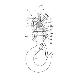
Fig. 1 is a sectional view of the hook connected to the free end portion of
the belt of the belt hoist according to the invention;
3
CA 02209642 1997-07-03
Fig. 2 is a sectional view taken on line X-X of Fig. 1;
Fig. 3 is a partly omitted, vertical sectional view of the belt hoist on the
winding member side only;
Fig. 4 is a partly cutaway, rear view of the same;
Fig. 5 is a partially broken) plan view of the belt hoist;
Fig. 6 is a rear view showing the entire structure of the belt hoist; and
Fig. 7 is a sectional view of another embodiment corresponding to Fig. 1.
DETAILED DESCRIPTION OF THE PREFERRED EMBODIMENT
Referring now to the accompanying drawing figures, an example of the
preferred embodiment of the invention is described below. It is to be
understood, however, that the scope of the invention is by no means limited to
the illustrated embodiment.
A belt hoist shown in Figs. 5 and 6 comprises a pair of spaced apart,
opposing first and second side plates 1A, 1 B and a cylindrical winding member
5 having a shaft insertion bore 51 at the center thereof and rotatably
supported
between the pair of first and second side plates 1 A, 1 B via a pair of
bearings.
In the shaft insertion bore 51 of the winding member 5, a drive shaft 31 is
rotatably supported via a pair of bearings. At an outside of the first side
plate
1 A, a motor 2 having a motor shaft 21 connected with the drive shaft 31 and
capable of rotating in a normal direction and in a reverse direction is
disposed.
The motor 2 forms a driving means. At an outside of the second side plate 1 B,
a reduction gear mechanism 3, including therein an over-loading prevent
mechanism 3B and a mechanical brake 3C, for reducing rotational speed of the
drive shaft 31 to a lower rotational speed to be transmitted to the winding
member 5 is disposed. The drive of the motor 2 drives the winding member 5
4
CA 02209642 1997-07-03
to be rotated in the normal direction or in the reverse direction through the
drive
shaft 31 and the reduction gear mechanism 3. The motor 2 is covered with a
cover 2A mounted on the first side plate 1 A, and the reduction gear mechanism
3 is covered with a cover 3A mounted on the second side plate 1 B.
The winding member 5 has a winding periphery 52 on which a flat belt 4 is
wound and disc-like winding flanges 53, 53 projecting from the winding
periphery 52 at the opposite ends thereof. The flat belt 4 has one end fixed
to
the winding periphery 52 and a free end portion to which a hook 6 is
detachably
joined.
The hook 6 comprises a generally J-shaped hook body 61, a hook's joint
63 in which the hook body 61 is rotatably held at the basal end thereof via a
thrust bearing 62, and a support rod 64 around which the free end portion of
the
belt 4 is wound, as shown in Figs. 1 and 2. The thrust bearing 62 and a
retaining ring 65 therefor are carried by the hook body 61 at the basal end
thereof.
The hook's joint 63 comprises two half joint bodies 63A, 63A, and two
fastening bolts 63B to join the joint bodies 63A, 63A together, abutting their
confronting surfaces to each other. The thrust bearing 62 and the retaining
ring 65 are housed and held in between the joint bodies 63A, 63A at lower ends
thereof. Further, each of the joint bodies 63A, 63A is provided at its upper
inside portion with first and second holding portions 66, 67. The first
holding
portions 66 are recessed with respect to the confronting surfaces of the joint
bodies and flatted to be contactable with the free end portion of the belt.
The
second holding portions 67 are curved inwards from lower ends of the first
holding portions 66 to hold the support rod 64. When the joint bodies 63A are
5
CA 02209642 1997-07-03
joined together by tightening the fastening bolts 63B, the supporting rod 64
is
held in sandwich or in a clipping manner by the second holding portions.
The free end portion of the belt 4 comprises a first coiling portion 41
wound around the support rod 64 in direct contact therewith, first and second
overlapping portions 42, 43 extending continuously beyond both end portions
of the first coiling portion 41, a second coiling portion 45 extending
continuously to the second overlapping portion 43 through a turn-up portion 44
so that it can be coiled in a direction opposite to the winding direction of
the first
coiling portion 41 to be wound around the first coiling portion 41 in direct
contact therewith, and third and fourth overlapping portions 46, 47 extending
continuously beyond both end portions of the second coiling portion 45 to
overlap the first and second overlapping portions 42, 43. An outer surface of
the second coiling portion 45 is contacted with the second holding portion 67
so
that the support rod 64 can be held in sandwich or in a clipping manner via
the
second coiling portion 45 and the first coiling portion 41, and further the
third
and fourth overlapping portions 46, 47 are contacted with and held in sandwich
or in a clipping manner by the first holding portion 66.
In the embodiment shown in Figs. 3 and 4, a random coil preventing
member 7 for normally pressing the tielt 4 against the winding periphery 52 of
the winding member 5 to prevent random coil of the belt 4 is swingably
supported on a pivot 70 between the first and second side plates 1 A) 1 B.
Also,
a control means 8 is provided for controlling the drive of the motor 2 by
swinging motion of the random coil preventing member 7 in response to
changes in circle diameter of the belt 4 wound around the winding member 5.
Further, a belt guide 9 with a belt guide bore 91 for allowing the belt 4 to
freely
6
CA 02209642 1997-07-03
pass therethrough is disposed below the random coil preventing member 7 in
such a manner as to be movable in the same direction as the swinging direction
of the random coil preventing member 7.
The random coil preventing member 7 comprises a pair of spaced apart,
opposing arms 71, 71 which are mounted on the pivot 70 rotatably supported
between the first and second side plates 1 A, 1 B; a rotary element 72
composed
of a roller which is rotatably supported to the arms 71 at the front end
portion
thereof via bearing means and is contactable with the belt 4; and a biasing
spring 73 for biasing the arm 71 toward the outer periphery of the winding
member 5 so that the rotary element 72 can be normally pressed against the
belt 4.
The control means 8 is provided in the following way. One lengthwise
end portion 70a of the pivot 70 is projected outward from the side plate 1 A.
First and second protrusions 81, 82, each being formed by protruding one end
portion of a boss having a fitting bore outward, are arranged on the projected
end portion 70a with a specified phase difference in the circumferential
direction and are secured thereto with screws so as to be changeable in
position. As depicted in a two-dot chain line in Fig. 3, at positions near the
projected end portion 70a and on swinging paths along which the first and
second protrusion 81, 82 movable in response to the turning of the pivot 70
are
swung, first and second detection switches 83, 84 are so arranged as to be
adjustable in position, respectively. The first detection switch 83, which is
formed by a limit switch and the like, is brought into contact with the first
protrusion 81 to stop the drive of the motor 2 when length of the belt 4 wound
around the winding member 5 decreases with the unwinding of the belt 4 and
7
CA 02209642 1997-07-03
circle diameter of the belt 4 decreases below a specified circle diameter. The
second detection switch 84, which is formed by a limit switch and the like, is
brought into contact with the second protrusion 82 to stop the drive of the
motor
2 when the length of the belt 4 wound around the winding member 5 increases
with the winding of the belt 4 and the circle diameter of the belt 4 increases
over
a specified circle diameter. In the illustrated embodiment, at the outside of
the
side plate 1 A, a cover 1 F for covering the protrusion 81, 82 and the
detection
switches 83, 84 is detachably attached to the side plate 1 A with fastening
screws, as shown in Fig. 4.
Next, operation of this constructed belt hoist is described below.
The belt 4, when wound onto or unwound from the winding member 5, is
guided by the belt guide 9, passing through the belt guide bore 91 of the belt
guide 9. With the winding or unwinding of the belt 4 onto or from the winding
member 5, a load hooked with the hook 6 fixedly connected to the free end
portion of the belt 4 is raised) lowered or dragged.
At the free end portion of the belt 4 to which the hook 6 is joined) the
support rod 64 is held in sandwich by the holding portion 67 in the condition
in
which the first coiling portion 41 is wound around the support rod 64 in
direct
contact therewith, and further a portion of the free end portion extending
from
the first coiling portion 41 is turned down at the turn-up portion 44 so as to
be
wound around the second coiling portion 45 in direct contact therewith. The
first and second coiling portions 41, 45 are coiled around the support rod 64
in
the opposite directions. As a result of this, the first coiling portion 41 and
the
second coiling portion 45 are strung in a direction of tightening the support
rod
64 by the load applied to the belt 4. This can provide the result that the
8
CA 02209642 1997-07-03
support rod 64 can be coiled double tightly by the first and second coiling
portions 41, 45 of the belt to prevent the free end portion of the belt from
falling
out from the hook. Thus, a firm connection of the hook to the free end portion
of the belt can be achieved.
Further, the provision of the turn-up portion 44 provide the advantage that
the coiling direction of the first coiling portion 41 and that of the second
coiling
portion 45 can be made opposite to each other easily. Also, the provision of
the first through fourth overlapping portions 42, 43, 46, 47 yields the
advantage
that the joint of the hook 6 to the belt 4 can be strengthened by fourfold
overlap
of the first through fourth overlapping portions 42, 43, 46, 47, together with
the
double tight coiling of the support rod 64 by the first and second coiling
portions
41, .45,
Further, the joint of the hook 6 to the belt 4 to be further strengthened by
holding the first through fourth overlapping portions 42, 43, 46, 47 in
sandwich
at the first holding portions 66, in addition to holding the support rod 64 in
sandwich at the second holding portions 67.
In addition, the third and fourth overlapping portions 46, 47 of the free end
portion of the belt, which are positioned outside and are contacted with the
first
holding portions 66 of the joint bodies 63A, 63A, as shown in Fig. 1, serve to
protect a load-applying portion of the belt 4 extending between the hook 6 and
the winding member 5 from contacting with the hook's joint 63. This can
provide the advantage that the belt 4 can be well protected from being worn
out
by contact with the hook's joint 63.
The embodiment described above, wherein the second coiling portion 45
is provided at a nearer side to the free end of the belt 4) and the first
coiling
9
CA 02209642 1997-07-03
portion 41 is provided at a further side therefrom, may be modified such that
the
first coiling portion 41 is provided at a nearer side to the free end of the
belt,
and the second coiling portion 45 is provided at a further side therefrom, as
shown in Fig. 7. In this modification also) the support rod 64 is held in
sandwich via the first coiling portion 41 and the second coiling portion 45
whose outer surface is contacted with the second holding portions 67, and
further the third and fourth overlapping portions 46, 47 are contacted with
and
held in sandwich by the first holding portions 66, as in the case of the Fig.
1
embodiment.
10