Note: Descriptions are shown in the official language in which they were submitted.
CA 02209875 1997-07-09
FASTENER DETECTION AND FIRING CONTROL SYSTEM FOR
POWERED FASTENER DRIVING TOOLS
BACKGROUND OF THE INVENTION
The present invention relates generally to improvements in portable fastener
driving
tools, such as powder actuated and combustion powered tools, and specifically
to
improvements relating to the detection of fasteners, the disabling of firing
systems when
absence of a fastener is detected, and operator notification when absence of a
fastener is
detected.
Portable combustion powered tools for use in driving fasteners into workpieces
are
described in commonly assigned patents to Nikolich, U.S. Pat. Re. No. 32,452,
and U.S.
Pat. Nos. 4,552,162, 4,483,473, 4,483,474, 4,403,722, and 5,263,439. Similar
combustion
powered nail and staple driving tools are available commercially from ITW-
Paslode of
Lincolnshire, Illinois under the IMPULSE~ brand.
CA 02209875 1997-07-09
Such tools incorporate a generally gun-shaped tool housing enclosing a small
internal combustion engine. The engine is powered by a canister of pressurized
fuel gas, also
called a fuel cell. A battery-powered electronic power distribution unit
produces the spark
for ignition, and a fan located in the combustion chamber provides for both an
efficient
combustion within the chamber, and facilitates scavenging, including the
exhaust of
combustion by-products. The engine includes a reciprocating piston having an
elongate,
rigid driver blade disposed within a piston chamber of a cylinder body.
A valve sleeve is axially reciprocable about the cylinder and, through a
linkage,
moves to close the combustion chamber when a work contact element at the end
of a
nosepiece connected to the linkage is pressed against a workpiece. This
pressing action also
triggers a fuel metering valve to introduce a specified volume of fuel gas
into the closed
combustion chamber from the fuel cell. The metering valve may take the form of
a solenoid
valve, which is powered by the battery, or may be a purely mechanical valve.
Upon the pulling of a trigger switch, which causes the ignition of a charge of
gas in the combustion chamber of the engine, the piston and driver blade are
shot downward
to impact a positioned fastener and drive it into the workpiece. As the piston
is driven
downward, a displacement volume enclosed in the piston chamber below the
piston is forced
to exit through one or more exit ports provided at a lower end of the
cylinder. After impact,
the piston then returns to its original, or "ready" position through
differential gas pressures
within the cylinder. Fasteners are fed into the nosepiece from a supply
assembly, such as a
2
CA 02209875 1999-09-29
supply tube or magazine, where they are held in a properly positioned
orientation for receiving
the impact of the driver blade.
A high velocity combustion powered tool of the same type having an extended
piston chamber or cylinder is the subject of a co-pending Canadian Patent
Application File
Number 2,182,340. The extended cylinder increases the stroke of the piston,
thereby allowing
for increased piston velocity and transfer of power from the driver blade to
the fastener.
In one embodiment, the extended length also allows an operator to stand
generally
upright while driving fasteners which are at foot level. Fasteners are loaded
into a supply tube
at operator level and positioned for firing into a nosepiece. Details of an
operator level loading
supply tube and associated nosepiece are disclosed in commonly assigned United
States Patent
No. 5,199,624 to Dewey et al, which may be referred to for further details.
One inconvenience associated with combustion tools is the need for fuel cell
replacement. Fuel cells used in the combustion tools may be used for a fixed
number of
combustions before becoming empty, at which time replacement is required.
Convenience is
enhanced when a cell lasts for a longer number of firings before replacement
is necessary.
On occasion, the supply assembly delivering fasteners into the nosepiece may
jam
or empty. While such condition is easily remedied, an operator may attempt to
fire the tool
before realizing that a fastener is not appropriately positioned in the
nosepiece. Such blank
firing reduces the number of fasteners driven per fuel cell, requiring more
frequent fuel cell
3
CA 02209875 1999-09-29
replacement.
In addition, the total number of fasteners driven before the tool itself needs
to be
serviced is reduced by blank firings. Among the parts which become worn or
broken over time
is the piston. At each firing, the piston violently impacts a bumper disposed
at the bottom of
the cylinder. Over time, this contact can cause premature failure of the
piston if blank firings
are permitted to occur. Useful tool life is therefore also reduced by blank
firings since fewer
fasteners are driven before service is necessary.
Similar problems are encountered in powder actuated (PAT) fastener driving
tools.
Various features of PAT fastener driving tools are described, for instance, in
United States
Patents Nos. 5,199,625 to Dewey et al and 4,824,003 to Almeras, et al which
also may be
referred to for further details. PAT tools are commercially available from
Societe de
Prospection et d'Inventions Techniques of Valence, France, a subsidiary of
Illinois Tool Works,
Inc. of Glenview, Illinois.
In contrast to the internal combustion tools, PAT tools rely upon a powder
cartridge
loaded magazine style into the combustion chamber. Similarly to combustion
tools, efficiency
of PAT tools is decreased by blank firings. Indeed, since a single powder
cartridge is used for
a combustion in the PAT tools, blank firings are even more inconvenient and
wasteful than in
an internal combustion tool, in which the fuel cell is useful for many
firings.
Accordingly, the present invention seeks to provide an improved combustion
powered
4
CA 02209875 1999-09-29
tool which extends useful fuel cell and tool life.
Further, the present invention seeks to provide an improved combustion powered
tool in which firing is prevented when a number of fasteners in a magazine
supply tube is
reduced to a predetermined number.
Still further, the present invention seeks to provide an improved combustion
powered tool wherein an operator is notified when the number of fasteners in
the magazine
supply tube is reduced to a predetermined number.
Further still, the invention seeks to provide an improved combustion powered
tool
including an optical detector to detect when the number of fasteners in the
magazine supply
tube is reduced to a predetermined number.
Yet further, the present invention seeks to provide an improved PAT tool
wherein
an operator is notified when the number of fasteners in the magazine supply
tube is reduced
to a predetermined number.
SUMMARY OF THE INVENTION
The present improved internal combustion powered fastener tool provides a
device
which prevents firing when the fastener supply tube level is reduced to a
predetermined
number. A detector placed along the fastener supply path determines whether or
not a fastener is present. When a fastener is detected, switches are
S
CA 02209875 1997-07-09
activated allowing fuel to be delivered from the fuel cell into the combustion
chamber, and
allowing spark to ignite the fuel. If a fastener is not detected, the switches
may disable either
or both fuel delivery and fuel ignition.
In a preferred embodiment, an extended length tool includes an optical sensor
as the
fastener detector. Positioning of a fastener into a predetermined part of the
fastener supply
path causes the optical sensor to enable fuel delivery and ignition circuits.
The tool may also
include an indicator to notify the operator when a fastener is not detected.
The indicator may
be visible, such as a light emitting diode (LED), and/or audible. An
alternative to the optical
sensor is a Hall effect sensor.
Various features of the present invention may also be applied to PAT tools.
Use of
a fastener detector and indicator on a PAT tool in accordance with the present
invention
provides notice to an operator that fasteners should be loaded prior to
firing.
A specific embodiment of the present invention provides a powered tool
arranged for
driving a driver blade to impact a fastener. A housing includes a main chamber
enclosing a
power source. An end of the driver blade is accepted into an aperture formed
within a
nosepiece associated with the housing. The aperture accepts a fastener and
guides the end of
the driver blade toward impact with the fastener. Fasteners are supplied into
the nosepiece
by a fastener supply tube associated with the housing. A fastener detector
detects the
presence or absence of a fastener within a portion of a fastener supply path
defined by
6
CA 02209875 1999-09-29
the supply tube. In response to a signal supplied by the detector, an
indicator notifies an
operator when the fastener detector detects the absence of a fastener and also
disables the
operation of the firing so that blank firing operation of the tool is
prevented.
BRIEF DESCRIPTION OF THE DRAWINGS
FIG. 1 is a fragmented side view of an extended stroke combustion fastener
tool in
accordance with the present invention.
FIG. 2 is an enlarged cross-sectional view of the power source of the fastener
tool
of FIG. 1.
FIG. 3 is a fastener detection and combustion disabling circuit constructed in
accordance with the present invention for use with a Hall effect fastener
sensor.
FIG. 4 is a fastener detection and combustion disabling circuit constructed in
accordance with the present invention for use with an optical fastener sensor.
DETAILED DESCRIPTION OF THE PREFERRED EMBODIMENT
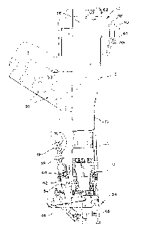
Referring now to FIGS. 1 and 2, the preferred embodiment of an extended length
high velocity combustion fastener tool suitable for practicing the present
invention is generally
designated 10. A main housing 12 of the tool 10 encloses a self contained
internal power
source 16, which is detailed in FIG. 2. The power source includes a combustion
chamber
that communicates with a cylinder 22. A piston 24 is disposed within the
7
CA 02209875 1997-07-09
cylinder 22 and is connected to a driver blade 28. In the preferred
embodiment, the cylinder
22 is of the extended length type and as such is considerably longer than the
driver blade 28.
Through depression of a trigger 30, an operator induces combustion of a
measured amount of propellant F, such as MAPP gas, within the combustion
chamber 20.
Propellant F is agitated by a fan 31 to help speed the combustion. In response
to the
combustion, the piston 24 is driven toward a terminal end 32 of the cylinder
22. As the
piston 24 approaches the terminal end 32, the driver blade 28 will be guided
into a nosepiece
34 and impact a fastener {not shown) held above a workpiece by the nosepiece.
Although
it is contemplated that the present tool will be used with a variety of
fasteners, it is preferred
that the fastener be of the so-called pin type, described in more detail in
U.S. Patent No.
5,199,625. Impact of the driver blade 28 drives the fastener into a workpiece
or substrate.
As a safety feature, and to regulate the use of fuel, the firing of the tool
will not occur unless
the nosepiece 34 is pressed against a workpiece. Such placement causes a
linkage rod 35 to
be pushed upward, which moves a valve sleeve 36 to seal the combustion chamber
20.
Details concerning sealing of the combustion chamber 20, and related
mechanisms may be
found in the previously mentioned Nikolich patents.
Upon ignition of propellant F in the combustion chamber 20, the piston 24 is
driven toward the terminal end 32 of the cylinder 22. A bumper (not shown) is
disposed
within the cylinder 22 at its terminal end 32 and defines the end of travel of
the piston 24
8
CA 02209875 1997-07-09
toward the terminal end 32, and differential gas pressures return the piston
back toward
combustion chamber 20 after the piston 24 completes its downward travel.
The tool 10 illustrated in FIG. 1 is a so-called extended length cylinder
embodiment. The particular illustrated embodiment of the extended length
cylinder 22
allows an operator standing generally upright to operate the tool 10 to drive
fasteners at foot
level. An important additional feature of the extended length tool 10 is the
increase in the
stroke of the piston 24. Through the increased stroke, velocity of the piston
at impact and
efficiency of power transfer is enhanced, when compared to an otherwise
identical
combustion powered tool having a smaller stroke.
As is known in the art, a PAT tool has a similar outer configuration to the
tool
10 of FIG. l, but relies upon explosion of a powder cartridge to drive the
piston 24.
Similarly to a firearm, a pom~der cartridge is disposed into a combustion
chamber, which is
equivalent to the chamber 20 of the combustion tool 10, is located above the
piston, and is
ignited through the striking of a hammer to drive a driver blade into a
nosepiece for impact
1 S with a fastener.
A fastener supply tube 38 is a ~ireferred supply assembly applicable to both
the
combustion tool 10 and PAT tools. An upper end of the flexible supply W be 38
is typically
attached to an upper portion of the housing 12, such as a handle 40, while a
lower end of the
supply tube 38 is attached to a nosepiece tube 42. The supply tube 38 may be
attached at
both ends by a suitable clamp 44. Fasteners 46 fed into an open end 48 of the
supply tribe
9
CA 02209875 1997-07-09
38 descend under the influence of gravity toward the nosepiece 34 and into the
nosepiece
tube 42. When an operator presses the nosepiece 34 against a workpiece, a
lowermost
fastener within nosepiece 34 is pushed by a shuttle block (not shown) attached
to a linkage
47 until it is positioned within a channel 48 of the nosepiece 34. In this
position, a fastener
may be struck by the driver blade 28.
Both the PAT and combustion tools are utilized in environments which demand
rapid cycling operation. An operator frequently repositions and fires the tool
in rapid fashion
to facilitate production. Operating under these or other conditions, an
operator may fail to
notice when the supply tube 38 becomes empty. Positioning of the nosepiece
near an
operator's foot and the opaque nature of the nosepiece 34 is an additional
impediment to
recognition that the supply tube 38 has become empty. Opaqueness of the supply
tube 38,
either by original design or accumulation of work environment dust and dirt
thereon,
similarly serves to reduce visibility of an empty condition of the supply tube
38.
Whatever the reason for an operator's failure to notice that the supply tube
has
1 ~ become empty, such failure to notice may lead to a blank firing of the
tool 10, e.g. a firing
when no fastener is positioned over the channel 48. Blank firing of the tool
reduces useful
tool life since the wear associated with firing of the tool is produced even
though no fastener
is driven.
Additionally, blank firing wastes propellant. In a PAT tool, a blank f ring
wastes a powder cartridge, requiring a magazine of powder cartridges to be
emptied more
CA 02209875 1997-07-09
quickly. In the combustion tool 10, a fuel cell 50 shown in FIG. 2 includes
sufficient
propellant F to drive a fixed number of cartridges, and propellant is wasted
during a blank
firing thereby requiring more frequent replacement of the fuel cell 50 by
operator removal
of a cap 52.
These and other inefficiencies associated with blank firing are alleviated in
accordance
with the present invention. Referring again to FIG. 1, the tool 10 in
accordance with the
present invention includes a fastener detector sensor 54 disposed along the
fastener supply
path defined by the supply tube 38 and nosepiece 34, including the nosepiece
tube 42.
Preferably, the sensor 54 takes the form of an optical sensor that is
responsive to a light
source. The optical detector and source, such as a photodetector and LED pair,
are mounted
at a predetermined location in the fastener supply path defined by the supply
tube 38 and the
nosepiece 34 so that the presence of a fastener will optically separate the
detector and source.
The LED and photodetector may be mounted internally or externally to the
supply path.
External mounting requires that the predetermined location in the fastener
supply path be
transparent to allow light from the LED to reach the photodetector, while
internal mounting
must avoid mechanical interference between fasteners and the sensor
components. External
mounting is more convenient for existing tools, while either mounting may be
easily
incorporated into the design of modified tools.
11
CA 02209875 1997-07-09
An alternative to the LED and optical sensor arrangement is a Hall effect
sensor S5,
which has a proximity detection capability that obviates the need to place the
switch within
the actual fastener supply path. Use of the Hall effect sensor 55 requires
fine calibration,
however, and the sensor has a tendency to drift during operation. In addition,
the Hall effect
sensor 55 is only responsive to fasteners made of soft magnetic material,
whereas the optical
sensor will operate irrespective of the type of material used for the
fastener. With either type
of sensor arrangement, the presence or absence of a fastener adjacent the
sensor 54 is
communicated to a fastener detection circuit within a circuit portion 56 of
the housing 12 via
leads 58.
Other sensors, such as a contact sensor may also be used in place of the
preferred
optical sensor. However, the contact sensor requires undesirable modification
of the fastener
supply tube 38 to permit fastener-to-sensor contact, thus introducing the
potential for
mechanical interference.
In the mechanically actuated PAT tools and in combustion tools having a
mechanical
fuel metering valve, warning is provided to an operator when the sensor 54
detects absence
of a fastener in the portion of the supply path adjacent thereto. The warning
12
CA 02209875 1997-07-09
is also preferably provided in the combustion tool 10 including an
electrically controlled
solenoid fuel metering valve, and may take the form of a light 60 disposed
within an
operator's line of sight, and/or a grille 62 for an audible alarm, or other
suitable alarm system
sufficient to notify an operator when the sensor 54 detects the absence of a
fastener. Upon
notice provided through the grille 62 or the light 60, an operator loads
additional fasteners
into the open end 48 of the supply tube 38 to avoid a blank firing.
In tools including electrical components in the firing system, blank firing
may
also be prevented firing when no fastener is detected. In addition, waste of
propellant may
be avoided if the propellant is normally supply through use of electrical fuel
metering
components.
Taking advantage of the electrical components incorporated ~ into the
combustion powered tool 10, the present invention contemplates disabling
combustion
ignition of the combustion powered tool when the sensor 54 detects the absence
of a fastener
in the portion of the fastener supply path adjacent the sensor 54. Referring
now to FIG. 2,
propellant F is introduced into the combustion chamber 20 through fuel
passageway 64 under
control of a solenoid fuel metering valve assembly 66. Electrical power for
the valve
assembly 66, fan 31, and spark coil 68 is provided by at least one battery 69
(best seen in
FIG. 1).
In conventional combustion powered tools, introduction of propellant F under
control of the valve assembly 66 occurs in response to pressing of the
nosepiece 34 against
13
CA 02209875 1997-07-09
a workpiece. Movement of the fan 31 to agitate the propellant F also occurs in
response to
the pressing of the nosepiece. Firing then occurs when the spark coil 68
ignites the propellant
F in response to depression of the trigger 30 by an operator. In a
conventional combustion
powered tool, this complete combustion process may be conducted even when the
fastener
supply tube 38 has emptied. According to the present invention, the combustion
process is
disabled when the sensor 54 detects absence of a fastener in the portion of
the fastener supply
path adjacent thereto. Either or both of the spark coil 68 and the fuel
metering valve
assembly 66 may be disabled to prevent firing when no fastener is detected.
The latter mentioned disablement of fuel delivery is not possible if the fuel
metering
valve assembly 66 is completely mechanical, but is preferred where a solenoid
valve or other
electromechanical valve is used in the valve assembly 66 because the
additional benefit of
fuel conservation is realized. Referring to FIG. 2, if blank firing is
prevented solely by
disablement of the spark coil 68, propellant is still introduced into the
combustion chamber
after the valve sleeve 36 is closed by action of the linkage rod 35. An
operator prevented
15 from firing the tool 10 by disablement of the spark coil 68 must lift the
tool to restart the
firing process thereby re-opening the combustion chamber 20 when the
13A
CA 02209875 1997-07-09
valve sleeve 36 moves down, and releasing the propellant which was introduced
into the
chamber. This waste of propellant is avoided by disabling the preferred
electromechanical
solenoid fuel metering valve assembly 66 when the sensor 54 detects that no
fastener is
present.
Referring now to FIG. 3, shown is a combustion disabling and alarm circuit 70
for
use where the sensor 54 comprises a Hall effect sensor 55. The circuit
generally includes an
oscillator section 72, a sensor section 74, an alarm section 76, and a
disabling section 78.
The oscillator section 72, including resistors Rl-R2, capacitor C 1, diode D 1
and
NAND gate A1 produces power pulses preferably at a low rate to reduce power
consumption
from the battery 69 by driving light emitting diode 60 (D2) for short
pulsating periods. Of
course, the same technique is preferably used to drive an audio alarm (not
shown 5 in FIG.
3) used in addition to or in place of the light emitting diode 60. While
circuit values may be
chosen to suit a particular application, the illustrated values produce an
oscillation pulse of
approximately 1 ms/s.
The sensor section includes a stable voltage source 80 for powering the Hall
effect
sensor SS, and for providing a selectable voltage to the voltage-following
comparator C1
through a voltage divider consisting of resistors R8 and R9, and variable
14
CA 02209875 1997-07-09
resistor VRl. The voltage output from the Hall effect sensor 55 is followed by
the output of
comparator C2. When the Hall effect sensor 55 detects a fastener, the voltage
output from
the comparator C2 exceeds the voltage output from comparator C 1 to drive the
output of
comparator C3 high. This drives the output of NAND gate A2 low, thereby
disabling diodes
D2 and D3, which otherwise respectively provide signals to disable the spark
coil 68 and the
fuel metering valve assembly 66. In addition, the low potential output from
the NAND gate
A2 disables NAND gate A3 through gate A4 to prevent pulses from the
oscillating circuit
section 72 from driving the light emitting diode 60.
Modification of the disabling and alarm circuit 70 for the PAT tools (and for
mechanically actuated combustion tools) simply requires omission of the
disabling circuit
section 78, since there is no electrical system to disable combustion in
typical PAT tools.
Exact placement of the Hall effect sensor SS along the fastener supply path
determines when
combustion disabling or alarming occurs. In the position illustrated in FIG.
1, disabling
occurs when two fasteners 46 are remaining within the nosepiece 34 including
the nosepiece
Vibe 42. This is a convenient location for mounting the Hall effect sensor 55,
but other
locations may also be used. Movement of the sensor 54 or 55 to a lower portion
of the
fastener supply path could reduce the predetermined number of fasteners which
trigger
disabling and alarm to one or zero. The number of fasteners may be similarly
raised by
moving the sensor 54 or 55 upward toward or upon the fastener supply tube 38.
The exact
2 0 placement of the sensor 54 will depend upon the shape of the fastener
used, and
CA 02209875 1997-07-09
should be aligned to produce the strongest response. As an example, the
preferred pin type
fasteners produced the strongest response when the Hall effect sensor 55 was
placed along
the supply path to align with a washer portion of the pin.
For reliability and ease of manufacture, the Hall effect sensor 55 preferably
has an
output which is proportional to a magnetic field generated by a magnet
attached to the back
of the sensor when it is mounted to the fastener supply tube 38. Outside the
presence of a
magnet, the output of the Hall effect sensor 55 would generally be a fixed
multiple of the
voltage supplied from the voltage source section 80, for instance 1/2. This
will increase once
the magnet is attached, and also increases when a fastener is proximate to the
Hall effect
sensor 55. However, there may be a variance in the amount of increase produced
by the
magnet depending upon the properties and exact sizing of the magnet which is
used.
Rather than providing more exacting tolerances for the magnet, variances in
the
produced magnetic field are accounted for during tool manufacture by setting
the voltage at
terminal 82 depending upon fastener and no-fastener voltages measured at
terminal 84. Using
the logic applied in the embodiment of FIG. 3, the output of C2 (terminal 84)
should be
smaller than that presented by C 1 (terminal 82) when no fastener is proximate
to the Hall
effect sensor 55. In the presence of a fastener the voltage presented by C2
should exceed that
presented by C 1. Preferably, the voltage at terminal 82 is set during
manufacture through
adjustment of the variable resistor VRl to be the midpoint between the no-
fastener and
16
CA 02209875 1997-07-09
fastener voltages measured at pin 84. This setting may be accomplished at any
time
subsequent to mating of the Hall effect sensor 55 and its magnet.
This process also confirms that the polarity of the magnet is properly aligned
with
respect to the Hall effect sensor 55. When the magnet polarity is in the
appropriate direction,
a fastener causes an increase in the voltage at terminal 84. A decrease is
observed if the
polarity is reversed.
These calibration difficulties are overcome by employing a sensor 54 including
an
optical detector and source, such as a photodetector 86 and LED 88, as shown
in FIG. 4.
The photodetector 86 and LED 88 are arranged so that a pulse 10 of light is
allowed across
the portion of the supply path where the sensor 54 is mounted in the absence
of a fastener,
and is blocked when a fastener is present.
An oscillator circuit 90 generates a 2ms pulse every second which causes the
driver
transistor Q11 to produce a similarly short pulse of light in the LED 88. If
no fastener is
present, the light pulse is received by the photodetector 86. A signal from
the photodetector
86 is amplified by an amplifier 92, formed from a buffer stage and two
capacitor coupled
gain stages. The capacitor coupling eliminates DC voltages. Peaks in the
amplified LED
signal are detected by a peak detector circuit 94 and used to determine the
presence or
absence of a fastener by a comparator C4, which has a reference voltage
applied to its
inverting input. When no fastener is present an output is produced by the
comparator C4 to
2 0 enable the NAND date A5, thereby allowing the
17
CA 02209875 1997-07-09
oscillator circuit to pulse the LED 60 (also shown in FIG. 1). When applied to
a
combustion tool, diodes D4 and DS are preferably used to provide signals to
disable the
spark coil 68 and the fuel metering valve assembly 66. Of course, when a
fastener is
present, the NAND gate is disabled so that the LED 60 is not pulsed and
disable signals
are not provided by diodes D4 and D5. Modification of the circuit of FIG. 4
for PAT
tools is realized by leaving outputs of the diodes D4 and DS unconnected, or
by omitting
the diodes and outputs entirely.
As described above with reference to the drawings, features of the present
invention provide for operator notification when fasteners have been depleted
to a
predetermined number in PAT and combustion powered tools, and disabling of
combustion
in the combustion tools when the same condition occurs. Some or all of these
features might
also be applied to other tools, such as pneumatic tools. Thus, while a
particular embodiment
of the fastener detection and firing control system for combustion and PAT
tools of the
invention has been shown and described, it will be appreciated by those
skilled in the art that
1 S changes and modifications may be made thereto without departing from the
invention in its
broader aspects and as set forth in the following claims.
18