Note: Descriptions are shown in the official language in which they were submitted.
CA 02209954 1997-07-04
CYCLONE SEPARATOR
This invention relates to a cyclone separator of the type used to separate
a mixture cornprising a fluid of a first density and fluid of a second
density, for example, oil and water.
The separation of a mixture of fluids, ~or example oil and water, into its
individual constituents is a~hieved in a kno\~vn type of hydrocyclone by
the generation of a vortex in the mixture within the hydrocyclone
effecting centrifugal separation of the mixture so as to produce an "oil-
core". The separated oil and water are collected individually at
respecti~e output ports. However, it has been found that transfer of the
oil frorn the oil-core to the oil output port ~ay be less than optimurn,
especially when the hydrocyclone is operating at low ~low/pressu~e with
consequent reduction in centrifugal for~es in the mixture.
According to a first aspect of the present invention, there is provided a
cyclone separator comprising a first chamber within which a separation
vo~tex is generated in use, said chamber having ~n end wall, an aperture
in s~id end wall, and, directin~ means tapering inwardly from said
ch~rnber towards said aperture for guiding a core of said vortex within
the first chamber to~vards the aperture.
Desirably said wall defines said directing rneans.
Conveniently said directing means substantially surrounds said aperture.
Preferably said directing means is a frusturn of a cone defined by saidwall with said aperture at its apical region
CA 02209954 1997-07-04
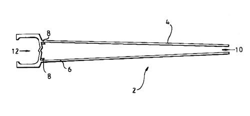
The invention will now be described, in more de~ail, vvith re~erence tothe accompanying drawings, in which:
Figure 1 shows a cross-section~l view of a hydrocyclone according to anembodimen~ of the present invention; and
Figure 2 shows a part of Figure 1 in more detail.
The hydrocyclone 2 of Figure 1 comprises a tapering tube element 4
having a water output port 10 at its narro~er end and an opposite end
portion 6 having one or more, desirably tangential, input ports 8, and an
oil output port 12.
Re~erring to Figure 2, the end portion 6 comprises a first chamber 14
defined in part by the tapering outer wall 26 of the tapering element 4.
The mixture inlet ports 8 are disposed in the wall 26 of the chamber 14
so as to be in fluid cornmunication therewith and the portion 6 further
includes a second chamber 16, and a dividing wall 18 separatin~ the first
and second chambers 14, 16. The dividing wall 18 h~s an aperture 20
located centrally therein and providing access from the chamber 14 to
the charnber 16, the chamber 16 including the oil outlet port 12.
The dividing wall 18 has a main, annular portion 28 of frusto-conical
shape v-~hich extends into the chamber 14 and tapers inwardly, having a
gener~trix inclined at an angle to ~ plane P which is perpendicular to a
central axis A of the hydrocyclone 2. The central portion 34 of the
dividing wall 18 is also of a frusto-conical shape which tapers inwardly,
but the portion 34 extends in the opposite direction to the portion 28,
CA 022099S4 1997-07-04
towards the second chamber 16, and has the aperture 20 disposed at its
apical region 36.
In use, an oil-water mixture is introdu~ed into the hydrocyclone 2 via the
inlet ports 8 so that a vortex is cre~ted within the first charnber 14 and
the tube elernent 4
The individual constituents, i.e. the oil and the water are separated, the
~ater component residing at the periphery of the vortex and the oil
component residing at the core of the vortex (known as an "oil-core").
The pressure balance within the hydrocyclone creates a b~ck pressure
providing the oil-core with an axial velocity tow~rds the dividing wall
18. The inwardly tapering portion 34 of the wall 18 directs the
peripheral portion of thç oil-core towards the aperture 20 thereby
minimising loss of transfer of the oil core from the first chamber to the
oil output port 12 in low inlet flow and pressure operating conditions.
The oil channelled from the oil-core to~vards the aperture 20 by the
portion 34 passes through the aperture 20 into the second chamber 16
and leaves the hydrocyclone 2 via the oil output port 12.
The water at the periphery of the vortex travels along the tube element 4
towards the water output port 10.
Although the above examples have been described in the context o~ the
dividing ~all 18 ha~in~ the main portion ~8 of frusto-conical shape, it i5
not intended ~hat the invention be limited to s~ch a ~onfiguration, other
configur~tions bein~ possible. For example, the main portion 28 can be
fo~med so as to have a flat or bulged shape. Similarly, the portion 34
CA 022099S4 1997-07-04
may h~ve a shape other than a frusto-conical configuration provided that
it possesses a sh~pe having an opening wider th~n the ~idest expected
"core" in use and capable of collecting and guiding fluid inwardly
tow~rds the aperture 20, for exarnple a curved, dished shape.
Additionally, although the above examples have been described in the
context of an oil-water rnixture, it is not intended that the invention be
limited to such a mixture and the use of other rnixtures is envis~ged, for
example water/gas or powder/water. In this respect, it is not intended
that the definition of tlle term fluid be limited to liquids and gasses
alone, but instead to include powders or solids suspended in liquids or
gases
