Note: Descriptions are shown in the official language in which they were submitted.
CA 02210150 1997-07-10
WO 96/21928 PCT/GB96/00036
~
SEMI-PERMANENT ENCLOSURE FOR OPTICAL DATA STORAGE DEVICE
The present invention relates to optical data storage media such as
compact discs and, in particular, to a semi-permanent enclosure for protecting
the edges and faces of such data storage media during use. The invention also
relates to a method of repairing minor surface defects and/or blemishes in
optical data storage media.
Optical data storage media are becoming increasingly commonplace in
everyday life. They are generally planar devices and have a substrate of clear
plastics material or glass on which a surface formation of data "pits" is
provided. The pitted surface is coated with a layer of diffused metal, such as
aluminium, which serves to reflect incident light passing through the
substrate
from its opposing face. Data is generally read by a laser shone through the
clear plastics material or glass, the incident light being distorted by the
data
pits and then reflected from the mirrored surfaces to be read by a pick-up.
For simplicity, in the text which follows, the term "disc" is used in a non-
limiting sense to refer to optical data storage media of various types.
Damage to the read surface, that is to say the surface through which the
laser reads the data pits, will result in distortion of the laser beam,
causing
errors in the reading of data. Similarly, damage to the reflective layer will
result
in a loss of reflectivity and loss of data, which will also lead to errors in
reading
of the data. A factor which is frequently overlooked is the possibility of
damage to the reflective layer from the non-read side of the disc.
It is also desirable to avoid damage to the edge of the disc. If the edge
becomes chipped, for example as a result of the disc being dropped, this may
result in the reflective surface becoming exposed. In such circumstances, the
reflective layer may tarnish and peel off. The purpose of the reflective layer
is
to reflect laser light back into the detector device of the playback
apparatus.
If the metallised layer is no longer reflective due to tarnish, or if portions
thereof are missing altogether, the playback apparatus will receive no data
from
the damaged portion of the disc and will therefore skip. Once exposure of the
CA 02210150 1997-07-10
WO 96/21928 PCT/GB96/00036
2
reflective surface has occurred, it is difficult to stop progressive
tarnishing and
delamination. A disc damaged in this way rapidly becomes completely
unplayable and must be replaced. Of course, in some cases, the stored data
is unique and cannot be obtained from alternative sources.
From the foregoing, it is clear that anv loss of laser light through
dispersal is undesirable since this reduces laser intensity and may result in
read
errors. To combat this, manufacturers produce optical data storage media
which have a degree of protection built in. The most vulnerable layers are the
pitted surface, on which the readable data is stored, and the metallised
layer.
During manufacture, these are sandwiched between layers of glass or plastics
material which form part of the completed disc assembly. The manufacturing
process may also include the provision of a label which is also provided with
a protective coating.
The present invention is defined as a "semi-permanent" enclosure in
order to distinguish it from protective layers such as those described above
which are provided as an inherent feature of the manufacturing process.
In addition to read errors resulting from surface damage to the disc as
outlined above, laser distortion may arise from non-planarity or imbalance of
the disc, for instance due to wobbling of the disc in a playback apparatus.
Such distortion is equally likely to result in read errors.
Protective shields for optical discs are known, for example as described
in United States Pate,nt No. 4,879,710. This patent discloses an optical disc
protector comprising a transparent annular protective sheet provided with
radially inner and outer rings of adhesive for securing the sheet to an
optical
disc. The adhesive rings are arranged so that they do not obscure the data
portion of the disc. Such an arrangement suffers from the drawback that the
film can be easily stripped at the edge of the disc due to the need for the
contact adhesive bands to be very narrow so as not to overlie the data
surface.
Subsequent peeling of the film allows dust and other particles to become
trapped under the film and to interfere with integrity of the laser signal. In
severe cases, the film may be lifted sufficiently to cause interference with
the
mechanics of the playback apparatus.
CA 02210150 1997-07-10
WO 96/21928 PCT/GB96/00036
3
In another protective arrangement known from United States Patent No.
4,736,966, an optical data storage device such as a data card is provided with
a plurality of peelable transparent protective layers. When a layer becomes
too
severely scratched for efficient reading of data, it is removed by peeling.
This
approach has a number. of disadvantages. Firstly, the data is obscured at the
outset by the number of layers interposed between the read surface and the
pick-up. This problem is exacerbated if the optical disc is intended for
recording as well as playback, since the signal to be recorded will be
attenuated by the interposed protective layers. Further attenuation occurs on
reading, so the playback signal may be very weak and severely distorted.
Another disadvantage is that the removal of successive layers by peeling
leaves
a residue of adhesive which needs to be cleaned away prior to playback. The
very act of cleaning may damage the next layer of protective film.
In European Patent Application No. 0 375 298 A2, a protective shield for
an optical disc is described which is designed to be stripped from the disc
immediately prior to the recording of data thereon by laser irradiation. The
shield thus serves to protect the disc in the post-manufacture phase, during
storage, transport and purchase by an end user. Such shields are formulated
with anti-static properties to minimise attraction of air-borne dust
particles.
This ensures that the data is recorded on a "clean" disc. However, no
provision is made for protecting the disc after recording.
European Patent Application No. 0 300 733 Al describes a heat-
shrinkable shield for optical discs. One of the drawbacks of this arrangement
is that specialist equipment is required to ensure even application of heat to
the
shield to effect shrinkage thereof around the disc to be protected.
Temperature
control is also important to prevent damage to the substrate. This arrangement
is therefore unsuitable for use by non-experts.
In British Patent Application No. 2 217 507 A, annular protective shields
are disclosed for attachment to compact discs through the intermediary of a
transparent or translucent gum. A special apparatus is also disclosed for
applying the shields to compact discs. The shields are shown attached to the
non-read surfaces of discs, since the applicant believes that the non-read
9 CA 02210150 1997-07-10
4
surface is particularly vulnerable to damage by virtue of having only a
relatively
thin protective layer of u.v.-curable lacquer. Whilst there are undoubtedly
some grounds for this belief, the document does not address the problem of
protecting the read surface- of optical discs from accidental damage.
It is therefore an object of the present invention to provide means for
protection against accidental damage to the opposed faces and edge surface
of an optical disc. It is a further object of the present invention to provide
means for protection against accidental damage to an optical disc which is
capable of being fitted by a non-expert and without the need for specialist
equipment. It is also an object of the present invention to provide means for
protection against accidental damage to an optical disc which means is capable
of being kept in place during use of the disc in standard playback apparatus,
including apparatu's having a multiple disc magazine, and which fits into a
standard disc "jewel" case for normal storage. It is yet another object of the
present invention to provide means whereby the dynamic qualities of an optical
disc are enhanced during use by elimination or suppression of wobbling or
other imbalances. It is a still further object of the present invention to
provide
a method of repairing minor surface defects and blemishes in such discs.
In a first aspect, the invention is an enclosure for an optical data storage
device, said enclosure comprising a first planar transparent film dimensioned
to overlie the read surface of an optical data storage device and a second
planar transparent film dimensioned to overlie the non-read surface of said
optical data storage device, said first and second films being provided with
rim
means having an L-shaped cross-section said rim means being dimensioned to
extend around the periphery of the optical data storage device, characterised
in that a uniform layer of solid malleable optical couplant is provided on at
least
the first film, on the surface thereof to be attached to said optical data
storage
device in use, said optical couplant having a refractive index compatible with
the refractive index of the optical data storage device.
Preferably, the rim means comprises upper and lower rim components.
The lower rim component may be formed of mild steel or material of similar
strength and characteristics. The thickness of the material from which the
<< r
'AME.NQED.SFiEE7'
CA 02210150 1997-07-10
lower rim is made may range from 20 to 800,um and its outside diameter may
range from 80 to 140 mm, depending on the diameter of the disc to which it
is to be applied. The lower rim component L-shaped cross-section is arranged
such that the vertical arm-df the "L" surrounds the edge of the disc whilst
the
5 horizontal arm of the "L" forms a lip on which the lower face of the disc
rests.
It will be generally understood that the lower surface of a disc is the data
read
surface since the upper surface is usually provided with a label and is non-
reflective. Typical dimensions for the vertical arm range from 200 ,um to 2.0
mm, whilst the horizontal arm may have a width of 200,um to 30 mm. The
selected width is chosen such that the lower rim component does not obscure
any part of the data-carrying surface of the disc.
If the lower rim component is formed of metal, it is preferably factory=
fitted to a clear, glossy and optically perfect film which is formed with a
hole
in its centre. The hole has a diameter ranging from 14 mm to 60 mm and is
dimensioned to accommodate the central raised spigot of a standard optical
disc. The inside diameter of the film is chosen such that a film covering
overlies the entire data-carrying surface of the disc. The film thickness may
range from 1,um to 600,um and the material of the film is chosen such that it
permits passage of laser light without significant distortion or attenuation.
Alternatively, the lower rim component may be an up-turned lip formed
integrally with the film.
The opticalcouplant assists in the establishment of an optically perfect
interface between the film and the data read surface of the disc.
Preferably, the refractive index of the optical couplant is chosen to be as
close as possible to that of the optical data storage device to which the film
is
to be attached. Most preferably, the refractive index of the optical couplant
differs by no more than 10% and most conveniently by no more than 5%
from the refractive index of the surface of the optical data storage device to
which it is attached in use.
Preferably, the optical couplant is a material, especially a silicone-based
material, capable of undergoing creep into minor defects on the surface of the
optical data storage device. This capability allows minor blemishes and
surface
~ ,. ,. ,.
y
AMENDED ~EET-
CA 02210150 1997-07-10
a = .. ,~'
6
asperities to be repaired so that playback losses are minimised and stored
data
is not compromised.
The optical couplant is a solid malleable material such as a transparent
solid rubberised silicone--or a transparent plasticised laminar coating, for
example polyvinyl chloride (PVC), interposed between the optical data storage
device and the film. Such plastic coatings exhibit a cling effect similar to
so-
called "cling-films" and so cohere to the film and the surface of the optical
data
storage device.
In another form of the invention, the film itself may perform the dual
function of protective device and optical couplant without the need for
separate
adhesive or cohesive material/layers.
As indicated above, the optical couplant facilitates comprehensivejoining
between the film and the laser read surface of the optical data storage
device.
No air or other contaminant is admitted between the two. The optical couplant
can be adhesive or cohesive in its action, and is preferably peelable to allow
removal of the film should this prove necessary. A protective enclosure in
accordance with the invention may need to be removed, for example, if it
becomes damaged and needs to be replaced with another.
Since optical discs are often formed with a plastics substrate such as
polycarbonate or acrylic resins, it is particularly advantageous to use films
formed from the same material. This ensures good optical matching between
the film, the optical couplant and the optical disc to which the film is
attached.
Cellulose triacetate has also been found suitable, even in the absence of an
optical couplarit: '
A film is also attached to the non-read surface of the optical disc to
ensure that its protection is comprehensive: This film may be a clear glossy
<< ..
Y
AMENDED S1-IEET
CA 02210150 1997-07-10
WO 96/21928 PCT/GB96/00036
7
plastics material and is preferably arranged such that indicia provided on the
non-read surface are still visible when the film is in place. The film need
not
be as optically perfect as the film used to protect the data read surface of
the
disc. The dimensions of the film for the non-read surface are most likely to
be
similar to those for the film used on the data read surface. Most preferably,
the
film attached to the non-read surface is integrally-formed with a down-turned
lip on its outer periphery which constitutes the upper rim component of the
rim
means and which co-operates with the aforementioned lower rim component.
This upper film is also provided with a central hole to accommodate the
central
spigot of the optical disc and may be coated with a contact adhesive on the
surface thereof which is destined to make intimate contact with the non-read
surface of an optical disc. The rim means may also have an adhesive coating
to bond upper and lower rim components together and/or to bond it to the disc
edge without causing interference to the laser read surface.
The rim means may have a reflective surface on the radially-inwardly
directed portion thereof to reflect dispersed laser light back into the device
and
thereby minimise losses and reduce data read errors.
The provision of rim means has an additional benefit in that the mass of
the rim creates an inertial effect as the disc is rotated in its
record/playback
apparatus. This means that the disc is less likely to wobble in the apparatus.
A wobbling disc would result in laser light being reflected at non-ideal
angles,
causing loss or reduction of laser signal and possible errors in or failure of
playback.
As indicated above, the rim means also protects the edge of the disc: If
the edge becomes chipped or otherwise damaged, the shiny metal layer on the
disc surface may be exposed and so become susceptible to peeling or
tarnishing. Once again, this could result in loss or reduction of laser signal
with
its inevitable consequences for playback.
Another advantage of the rim means is that it can be configured to
prevent the protective film surfaces from coming into contact with any planar
surface on which the optical disc is rested.
CA 02210150 1997-07-10
-=
8
The rim means may be provided as a pair of interengageabie parts which
snap together, one being applied in the direction of a first side (face) of an
optical disc and the other being applied; in the opposite direction, from the
other side of the device. The two rim portions are releasably engaged so that
they can be separated to allow removal of films if required.
In another variation, the rim means is provided with minute channels at
the edges through which trapped air can be expelled. Such channels facilitate
effective application of the films to the optical disc by ensuring that there
are
no discontinuities at the interface between the film and the optical disc.
Conveniently, an upper rim/film assembly is factory-supplied with a
transparent contact adhesive so that it can be stuck to the top label surface
of
an optical disc and also grips the lower rim component to hold it in place.
The rim me8lis is dimensioned to allow use of the present invention with
magazines of optical discs with autqmatic changing apparatus, for example
multi-disc CD players. Such rims must be sufficiently robust that they are
capable of withstanding the handling forces encountered in the automatic
changing apparatus whilst retaining the protective films in place.
The rim components may be integrally formed with a respective film
member, or may be separate therefrom. The rim means may be secured to a
respective film member by welding or some other form of permanent bonding.
If the rim component is metal, the reflective radially-inwardly directed
surface
may simply be the bright finish of the metal itself.
In a second aspect, the invention provides a method of repairing minor
defects and/or blemishes on the laser read surface of an optical data storage
device, the method comprising the steps of:
(a) applying a first planar transparent film over the laser read surface of
said optical data storage device, said first film having a uniform layer of
solid malleable optical couplant on the surface thereof adapted for
attachment to said optical data storage device;
(b) squeezing any air from between,said first film and the optical data
storage device;
AMENDED SHÃEi
CA 02210150 1997-07-10
. . =, ,
9
(c) allowing the optical couplant to creep into the damaged regions of
the surface of said optical data storage device;
(d) applying a second planar transparent film over the non-read surface
of said optical data storage device, and
(e) retaining said first and second films in place with rim means having
an L-shaped cross-section extending around the periphery of the optical
data storage device.
The method defined above is capable of curing minor surface defects for
as long as the film remains in place. The optical couplant creeps into
scratches
and like surface blemishes to leave a surface which is readable by incident
laser
without losing focus. If the film is removed, however, the damage will become
apparent again arTCe the surface is cleaned.
A more permanent optical co~jplant could be used which would remain
in place after removal of the film and after cleaning.
AMENDED SHEFT
CA 02210150 1997-07-10
WO 96/21928 PCT/GB96/00036
The invention will now be described by way of example only with
reference to the drawings, in which:
Figure 1 is a view from below of one embodiment of the invention,
showing an upper rim and a film member; =
5 Figure 2 is a view from above of the arrangement depicted in Figure 1;
Figure 3 is a view from above of a lower rim and film in accordance with.
the invention;
Figure 4 is a view from below of the arrangement shown Figure 3;
Figure 5 is an exploded side view of upper and lower rims and films prior
10 to their attachment to an optical storage device;
Figure 6 is a side view in cross-section of the components shown in Figure
5 after assembly, and
Figure 7 is a close-up view of the arrangement depicted in Figure 6,
showing detail of the co-operating rims.
Referring now to Figures 1 and 2, these views show the bottom and top
views, respectively of an upper rim 20 and film 30 for use with a laser-
readable
compact disc (not shown). The upper film 30 has a central cut-out 31 to
accommodate a central boss of the compact disc. Typically, the diameter of
the cut-out 31 is arranged to be larger thari the diameter of the central boss
of
the compact disc because the internal rim region of such bosses is utilised in
reproduction equipment to centralise and grip the disc during playback.
Figure 1 shows a rim edge 21 which slightly overlies the outer periphery
of the film 30, and a rim lip 22. The rim lip 22 should be regarded as
extending outwards from the plane of the drawing and is only shown here
schematically as a circle surrounding the rim edge 21.,
Figure 2 merely shows the rim edge 21 from above. In this view, the rim
lip is not visible but may be regarded as projecting from beneath the plane of
the drawing.
Figures 3 and 4 are similar views to Figures 1 and 2, except that they show
top and bottom views, respectively of a lower rim 40 and film 50 for use
with the laser-readable compact disc. Like its upper counterpart, the lower
film
CA 02210150 1997-07-10
WO 96/21928 PCT/GB96/00036
11
50 has a central cut-out 51 to accommodate the central boss of the compact
disc. For the reasons given above, the diameter of cut-out 51 is larger than
the
diameter of central boss of the compact disc.
In Figure 3, a rim edge 41 is shown slightly overlying the outer periphery
of the film 50. Rim 40 has a rim lip 42 shown here schematically as a circle
surrounding the rim edge 41. This lip 42 should be regarded as extending
outwards from the plane of the drawing. In Figure 4, rim lip 42 is not
visible.
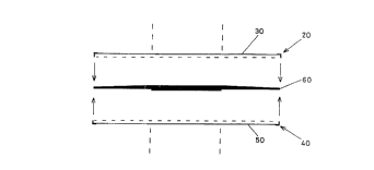
Figure 5 is an exploded view of the upper 20 and lower 40 rims and their
respective film members 30 and 50, prior to attachment to a compact disc 60.
In practice, one of the upper or lower assemblies would be selected for
attachment to a first surface of the compact disc 60. Any air bubbles which
are trapped between the first surface of the disc and the film which is
attached
first are squeezed out by stroking the film gently in a radially outward
motion.
Conveniently, the rim members may be provided with minute channels at their
edges through which trapped air can be expelled. Such channels are not
shown in the drawings.
When the attachment of the first assembly to the first side of the disc
is complete, the second assembly is offered up to the second face of the disc
and the above process of air bubble removal is repeated. The respective rim
portions are releasably clipped together to form a unitary retaining mechanism
for the upper and lower films.
The fully assembled arrangement is shown in cross-section in Figure 6.
Compact disc 60 is securely sandwiched between upper and lower film
members 30 and 50 by the intermediary of fluid optical couplant such as the
silicone preparations described previously.
Figure 7 is a close-up view of the interengaging rim members. In this
view, the rim members are clearly shown as separate entities from their
associated film members. However, as mentioned above, the rim members
may be integrally formed with the film members or may be permanently bonded
thereto such as by welding. It is also possible to have one film with an
integrally-formed rim component and one film with a permanently-bonded rim
CA 02210150 1997-07-10
WO 96/21928 PCT/GB96/00036
12
component, or combinations of,the above with a separate rim and film sub-
assembly.
The purpose of the protective cover on the laser read surface of the disc
is to minimise or prevent scratch damage. Damage to this surface causes laser
light to be dispersed by reflection from the scratch which results in the data
carried in that light being lost. The disc then skips. If the scratch is
circular,
it is more likely to impair the reading of the disc because the laser'reads in
a
circular motion. Scratches across the disc are less of a problem because the
laser can re-scan the disc to find the lost data, provided always that the
scratch is not too wide. Scratch damage near the centre of the disc may very
well result in the entire disc being unplayable since the laser begins its
scan
here and must be able to identify the start of the recorded data. This is
analogous to the start groove at the outer periphery of a gramophone disc
tracked by a stylus.
Similar considerations apply in relation to the film applied to the non-read
surface of a disc. Here, the purpose of the protective film is to prevent or
minimise damage to the non-read surface to the extent that corruption of the
reflective metallised layer is avoided. Minor blemishes on the non-read
surface
are not such a problem, but the enclosure of the present invention imparts an
extra degree of protection which contributes to the longevity of optical
discs.
If the film is scratched, the damaged enclosure can be removed and
replaced with a new unit having undamaged surfaces. In some embodiments,
replacement of the defective part of the enclosure is all that is required and
undamaged components can be re-used.
Where an optical couplant with favourable creep properties forms part
of the enclosure, application of such an enclosure to a disc moderately
damaged on its laser read surface is often sufficiently effective to cure the
scratch damage and thereby restore the disc.
One of the main purposes of the rim means is to hold the enclosure in
place on a disc. It also acts, by virtue of its mass, as an inertia device
which
helps the disc to spin more evenly in the playback apparatus. To be effective
in this role, the rim means should have a minimum mass of 1 gram. Discs tend
CA 02210150 1997-07-10
13
to wobble slightly in playback apparatus, which means that a small proportion
of laser light is lost by reflection at non-ideal angles. Normally, a small
decrease in light intensity is not a problem, but it can be critical if the
disc is
soiled by dust or fingerprints, for example. If wobbling coincides with a
dirty
region of the disc, the laser intensity may drop to a level which causes
skipping
to occur. Hence, elimination of wobbling makes the playback apparatus more
tolerant of surface imperfections on the disc.
As mentioned previously, another function of the rim means is to protect
the disc edge from damage by chipping. However, the rim means is also
helpful in preventing surface damage to the d.isc because it raises the bottom
surface of the disc slightly from any surface on which it might be placed when
not in its storage case or in use.
Although the invention has been particularly described with reference to
one preferred embodiment, it will beunderstood by persons skilled in the art
that various modifications are possible without departing from the scope of
the
claims which follo.w. For example, the invention. may be adapted to optical
data storage 'devices having two readable faces by using optically perfect
films
on both sides, said films being provided with a solid malleable optical
couplant
on the faces thereof which contact the surface of the optical data storage
device.
,._
AI1AElVOED SIIEET