Note: Descriptions are shown in the official language in which they were submitted.
CA 02210239 1997-07-11
INTEGRAL TUBING HEAD AND ROTATOR
FIELD OF INVENTION
The within invention relates to a tubing head designed to accommodate a
tubing rotator therein such that the tubing head may be retrofit with the tubing rotator.
Further, the within invention relates to an apparatus for attachment to a wellhead for
suspending and rotating a tubing string within a wellbore, the apparatus comprising a
tubing head and a tubing rotator combined to form a single, integral unit.
BACKGROUND ART
A typical wellhead is often comprised of a casing head or a casing bowl
which engages or is otherwise mounted to a casing string contained within a wellbore
of a well at the surface. A tubing head or tubing bowl is mounted upon the uppersurface of the casing head and provides a support mechanism for a tubing hanger. The
tubing hanger is connected to or engages the upper end of the tubing string which is
contained within the wellbore. Thus, the tubing hanger and the tubing string
connected thereto are supported at the surface of the well by the tubing head.
Alternately, the wellhead may not include a casing head. In this case, the tubing head
is mounted directly to the casing string at the surface of the well. A reciprocating rod or
tube or a rotating rod or tube is then run through the tubing string for production of
the well.
A typical wellhead may also further include a tubing rotator. Tubing
rotators are used in the industry to suspend and rotate the tubing string within the
wellbore. By rotating the tubing string, typical wear occurring within the internal
surface of the tubing string by the reciprocating or rotating rod string is distributed over
the entire internal surface. As a result, the tubing rotator may prolong the life of the
tubing string. Further, the constant movement of the tubing string relative to the rod
string may inhibit or reduce buildup of wax and other materials within the tubing
string.
Conventional tubing heads are not typically able to be retrofitted to
accommodate the necessary structure of a tubing rotator, including the drive system for
causing the rotation of the tubing string. Thus, the tubing head may require
replacement in the event the operator of the well chooses to commence the use of a
-1-
CA 02210239 1997-07-11
rotator subsequent to the initial completion of the well and the wellhead. Further,
when a conventional tubing rotator is used in combination with a conventional tubing
head, the rotator is typically mounted on top of the tubing head. This arrangement
may increase the overall height of the wellhead and may result in the instability of the
5 wellhead by weakening its overall structure.
As well, in order to service the well, the tubing hanger and the connected
tubing string must typically be removed from the well. However, any disturbance of
the tubing string during servicing may lead to a blowout. To avoid this risk in a
10 conventional well without a tubing rotator, the portion of the wellhead above the
tubing head is typically removed and a blowout preventer is mounted to the tubing
head. The tubing hanger with the attached tubing string are then removed throughthe blowout preventer.
Where the wellhead includes a tubing rotator, the structure of the rotator
tends to interfere with the installation of the blowout preventer. Thus, in order to
service the well, the rotator, or at least a portion of it, must typically be removed from
the tubing head. Removal of all or a portion of the rotator may require or result in
disturbance of the tubing string, which may lead to a blowout.
Further, when a rotator is in use in the wellhead, the tubing hanger is
typically comprised of a swivel dognut assembly. The swivel dognut assembly is
comprised of a rotatable mandrel, which is connected to and suspends the tubing string
within the wellbore, and a drive system for rotating the mandrel which results in the
25 rotation of the tubing string. The drive system is conventionally comprised of a system
of gears which engages the mandrel either directly or indirectly to cause it to rotate. In
order to remove these conventional rotators and tubing hangers for servicing of the
well, the gear system must first be removed from the rotator such that the mandrel is
no longer directly or indirectly engaged thereby. Where the gear system is not so
30 removed, due to an error or oversight, the rotator and the wellhead may be seriously
damaged resulting in the costly replacement of equipment, a loss of production during
replacement of the equipment and a potential for the blowout of the well.
As well, in order to service the well, a pup joint or servicing tool is
35 typically threaded into the upper end of the inner rotatable mandrel of the swivel
tubing hanger. However, upon the removal of the drive system for servicing of the
well, the inner mandrel is typically able to freely rotate within the outer supporting
--2--
CA 02210239 1997-07-11
structure of the tubing hanger. As a result, connection of the servicing tool may be
problematic due to the difficulties encountered in obtaining and ensuring a secure
connection between the servicing tool and the inner mandrel of the tubing hanger.
This problem is typically addressed by the insertion of a key between the inner mandrel
5 and the outer supporting structure of the tubing hanger during servicing of the well in
order to inhibit the rotation of the inner mandrel.
There is therefore a need in the industry for a tubing head capable of
accommodating the functional structure or elements of a tubing rotator therein such
10 that the tubing head may be retrofit and converted from its use as a conventional
tubing head into its use as a combined tubing head and rotator. Further, there is a need
for an apparatus which combines the functional elements of a tubing head and a tubing
rotator in a single, integral unit.
As well, there is a need for such a tubing head and apparatus that are
relatively compact and that will facilitate the servicing of the well. More particularly,
there is a need for such a tubing head and apparatus that permit the removal of the
tubing string from the well therethrough without first requiring the removal of all or a
portion of the tubing head or apparatus, including the drive system of the tubing
20 rotator. Further, there is a need for such a tubing head and apparatus which permits
the removal of the tubing string through a service blowout preventer mounted
thereon without first moving the tubing string connected to the tubing rotator.
Finally, there is a need for such an apparatus that facilitates the connection of a
servicing tool to the components of the tubing rotator during the servicing of the well.
DISCLOSURE OF INVENTION
The present invention relates to a tubing head capable of accommodating
the functional structure or elements of a tubing rotator therein such that the tubing
30 head may be retrofit and converted from its use as a conventional tubing head into its
use as a combined tubing head and rotator. Further, the present invention relates to an
apparatus which combines the functional elements of a tubing head and a tubing
rotator in a single, integral unit.
As well, the present invention preferably relates to such a tubing head and
apparatus that are relatively compact and that will facilitate the servicing of the well.
In addition, the present invention relates to such a tubing head and apparatus which
-3-
CA 02210239 1997-07-11
are configured such that the tubing string is removable from the well therethrough
without first requiring the removal of all or a portion of the tubing head or apparatus,
including the drive system of the tubing rotator. Further, the present inventionpreferably relates to such a tubing head and apparatus which are configured such that
5 the tubing string is removable through a service blowout preventer mounted thereon
without first moving the tubing string connected to the tubing rotator. Finally, the
present invention preferably relates to such an apparatus which facilitates the
connection of a servicing tool to the components of the tubing rotator of the apparatus
during the servicing of the well.
In a first aspect of the invention, the invention relates to a tubing head for
accommodating a tubing rotator therein, the tubing head being of the type having an
upper end, a lower end for attachment to a wellhead and an internal bore extending
between the upper and lower ends, wherein the tubing rotator comprises a drive gear
15 and a swivel tubing hanger for rotatably suspending a tubing string contained within a
wellbore, the tubing hanger comprising an external surface for engaging the internal
bore of the tubing head such that the tubing hanger may be suspended thereby and a
driven gear for engaging the drive gear, the improvement which comprises:
(a) the internal bore of the tubing head defining an internal surface for
engaging the external surface of the tubing hanger such that the tubing
hanger may be suspended by the tubing head; and
(b) the tubing head defining a gear housing for containing the drive gear
therein, wherein the gear housing communicates with the internal bore
such that the drive gear may releasably engage the driven gear of the
tubing hanger when the tubing hanger is suspended by the tubing head;
wherein the internal surface, the gear housing, the drive gear and the driven gear are
30 configured such that when the drive gear is contained within the gear housing, the
tubing hanger is located in the internal bore and the driven gear is engaging the drive
gear, the tubing hanger is capable of being removed from the internal bore by pulling it
through the upper end of the tubing head without first disengaging the drive gear from
the driven gear.
CA 02210239 1997-07-11
In a second aspect of the invention, the invention relates to an apparatus
for attachment to a wellhead for suspending and rotating a tubing string contained
within a wellbore, the apparatus comprising:
(a) a tubing head having an upper end, a lower end for attachment to a
wellhead and an internal bore extending between the upper and lower
ends, wherein the internal bore of the tubing head defines an internal
surface and wherein the tubing head further defines a gear housing which
communicates with the internal bore;
(b) a swivel tubing hanger for locating within the internal bore and for
connecting to the tubing string, the tubing hanger comprising a driven
gear and an external surface for engaging the internal surface of the tubing
head such that the tubing hanger may be suspended by the tubing head;
and
(c) a drive gear for containing within the gear housing and for releasably
engaging the driven gear of the tubing hanger;
20 wherein the internal surface, the gear housing, the drive gear and the driven gear are
configured such that when the drive gear is contained within the gear housing, the
tubing hanger is located in the internal bore and the driven gear is engaging the drive
gear, the tubing hanger is capable of being removed from the internal bore by pulling it
through the upper end of the tubing head without first disengaging the drive gear from
25 the driven gear.
In the first and second aspects, any configuration of the tubing head able to
achieve the functions or purpose of the tubing head as described above may be used
However, preferably, the internal bore of the tubing head defines a minimum diameter
30 of the bore. Further, the gear housing is preferably configured such that when the
drive gear is contained within the gear housing, it does not protrude into the internal
bore within the minimum diameter. As well, the internal surface of the tubing head
preferably defines a maximum diameter of the internal bore which is about equal to a
maximum diameter of the tubing hanger. When a service blowout preventer is
35 mounted on the upper end of the tubing head and the tubing hanger is located in the
internal bore, the maximum diameter of the tubing hanger preferably permits the
CA 02210239 1997-07-11
tubing hanger to be removed from the internal bore by pulling it through the blowout
preventer in order to service the well.
Further, in the preferred embodiment, the drive gear and the driven gear
5 engage each other between the minimum diameter and the maximum diameter of theinternal bore. The drive gear and the driven gear may be comprised of any compatible
gears suitable for performing their functions or purpose and which engage each other
between the minimum and maximum diameters of the internal bore. However,
preferably, the drive gear is comprised of a worm and the driven gear is comprised of a
10 worm gear. Further, in the preferred embodiment, the worm and the worm gear are
non-enveloping in order to facilitate the removal of the tubing hanger from the
internal bore without first disengaging the worm from the worm gear.
The worm gear is comprised of a plurality of worm gear teeth and the
15 worm is comprised of a plurality of worm teeth. These worm gear and worm teeth
may have any shape or configuration permitting the removal of the tubing hanger
from the internal bore without first disengaging the worm from the worm gear. Inaddition, the shape and configuration preferably facilitate the feeding of the worm gear
onto the worm and the feeding of the tubing hanger into the internal bore of the20 tubing head. In the preferred embodiment, a lower end of each worm gear tooth is
tapered inwardly towards a centre of the tooth in order to facilitate the feeding of the
worm gear onto the worm. In addition, the lower end of each worm gear tooth is
sloped downwardly from a top face to a bottom face of the tooth in order to facilitate
the feeding of the tubing hanger into the internal bore of the tubing head. Finally, a
25 crest of each worm tooth is tapered to facilitate the feeding of the worm gear onto the
worm.
The tubing head is preferably further comprised of any means, structure,
mechanism or device for inhibiting the longitudinal movement of the tubing hanger
30 in a direction toward the upper end of the tubing head. Preferably, the upwards
longitudinal movement of the tubing hanger is inhibited by the tubing head which is
comprised at least one adjustable holddown screw for engagement with the tubing
hanger such that when the holddown screw is adjusted for engagement with the
tubing hanger, longitudinal movement of the tubing hanger in a direction toward the
35 upper end of the tubing head is inhibited. In the preferred embodiment, the tubing
head is comprised of at least two holddown screws located adjacent the upper end of
the tubing head.
-6-
CA 02210239 1997-07-11
In addition, the tubing head is further preferably comprised of means for
mounting the tubing head on the wellhead. Any means, mechanism, structure or
device capable of and suitable for temporarily or permanently mounting or connecting
5 the tubing head to the wellhead may be used. Preferably, the mounting means are
capable of connecting the lower end of the tubing head on the wellhead. In addition,
the mounting means may be suitable for mounting or connecting the lower end of the
tubing head to any portion or component of the wellhead, but preferably, the
mounting means are compatible with mounting the tubing head to a casing string or a
10 casing head or an existing tubing head.
For instance, when the wellhead is comprised of a casing string, the
mounting means may be comprised of a mounting portion of the internal bore of the
tubing head adjacent the lower end, which mounting portion is adapted for connection
15 to the casing string. When the wellhead is comprised of a casing head or an existing
tubing head, the mounting means may be comprised of a lower surface on the lowerend of the tubing head, which lower surface is adapted for connection to the casing
head or the existing tubing head. Preferably, in this case, the lower surface of the tubing
head is comprised of a mounting flange.
Finally, the tubing head is further preferably comprised of means for
connecting the upper end of the tubing head to other wellhead equipment. Any
means, mechanism, structure or device capable of and suitable for temporarily orpermanently mounting or connecting the upper end of the tubing head to the other25 wellhead equipment may be used.
The tubing hanger may be comprised of any swivel tubing hanger
compatible with its use within the tubing head and which permits the functioning of
the apparatus as described herein. However, preferably, the tubing hanger is further
30 comprised of: a supporting member comprising the external surface of the tubing
hanger; and a supported member rotatably supported within the supporting member
such that the longitudinal movement of the supported member relative to the
supporting member in a direction toward the lower end of the tubing head is inhibited,
the supported member having an upper end and a lower end for connecting to the
35 tubing string and wherein the supported member is associated with the driven gear
such that rotation of the driven gear causes the supported member to rotate within the
supporting member.
--7-
CA 02210239 1997-07-11
The supported member may be associated with the driven gear in any
manner or by any means, mechanism, structure or device which permits the
functioning of the tubing hanger as described herein and which permits the drive gear
5 to engage the driven gear. However, in the preferred embodiment, the driven gear is
fixedly mounted about the supported member such that the driven gear extends from
the supported member towards the gear housing of the tubing head for engagement
with the drive gear.
The tubing hanger further preferably comprises means for inhibiting the
longitudinal movement of the supported member relative to the supporting member
in a direction toward the upper end of the tubing head. Any means, structure,
mechanism or device for inhibiting the upwards longitudinal movement of the
supported member relative to the supporting member may be used. However,
15 preferably, the inhibiting means is comprised of the abutment of the driven gear and
the supporting member.
Any means, mechanism, device or structure capable of supporting the
supported member in the required manner which is compatible with the function of20 the tubing hanger, may be used. However, preferably, the supported member is
rotatably supported within the supporting member by at least one bearing locatedbetween the supported member and the supporting member such that the bearing is
seated on the supporting member and the supported member is rotatably supported
upon the bearing. Any bearing suitable for, and compatible with, this intended
25 purpose or function may be used. For instance, the bearing may be comprised of a
thrust bearing, a radial bearing, a tapered roller bearing or a combination thereof. In
the preferred embodiment, the bearing is comprised of a thrust bearing in combination
with a bushing sleeve.
30 BRIEF DESCRIPTION OF DRAWINGS
Embodiments of the invention will now be described with reference to
the accompanying drawings, in which:
Figure 1 is a top view of a preferred embodiment of the apparatus of the
within invention;
CA 02210239 1997-07-11
Figure 2 is a side view of the preferred embodiment of the apparatus
shown in Figure 1;
Figure 3 is a longitudinal sectional view of the preferred embodiment of
5 the apparatus taken along line 3-3 of Figure 1;
Figure 4 is a cross sectional view of the preferred embodiment of the
apparatus taken along line 4-4 of Figure 2, showing in detail a drive system comprising
a worm and a worm gear;
Figure 5 is a bottom view of the worm gear shown in Figure 4, shown in
isolation;
Figure 6 is a side view of the worm gear shown in Figure 5;
Figure 7 is a longitudinal sectional view of the worm gear taken along
line 7-7 of Figure 5;
Figure 8 is a longitudinal sectional view of an alternate embodiment of
20 the apparatus, taken along a line similar to that of Figure 3 for the preferred
embodiment;
Figure 9 is a longitudinal sectional view of a preferred embodiment of the
tubing head of the within invention, taken along a line similar to that of Figure 3 for
25 the preferred embodiment of the apparatus, shown in use with a non-swivel tubing
hanger; and
Figure 10 is a cross sectional view of the preferred embodiment of the
tubing head taken along line 10-10 of Figure 9.
BEST MODE OF CARRYING OUT INVENTION
Referring to Figures 1-3, the within invention is directed at an apparatus
(20) for attachment to a wellhead for suspending and rotating a tubing string contained
35 within a wellbore. More particularly, the apparatus (20) combines the functions of a
tubing head (22) and a tubing rotator in a single, integral unit. Further, referring to
Figure 9, the within invention is further directed at an improved tubing head (22) for
g
CA 02210239 1997-07-11
attachment to the wellhead, which is able to accommodate the functional features or
elements of a tubing rotator.
A typical wellhead is comprised of a plurality of components mounted at
5 the ground surface above the wellbore. A rod or rod string is run through the
wellhead and into the wellbore through a continuous fluid passage or pathway which
extends through each of the components of the wellhead. The well may be producedby a reciprocating rod or tube, reciprocated by a pump jack or walking beam at the
surface, or by a rotating rod or tube, driven by a rotary pump drive at the surface.
Further, a typical wellhead is comprised of a casing head or a casing bowl
which engages or is otherwise mounted to a casing string contained within the
wellbore of the well at the surface. A tubing head or tubing bowl may be mountedupon the upper surface of the casing head to provide a support mechanism for a tubing
15 hanger. The tubing hanger is connected to or engages the upper end of a tubing string
which is contained within the wellbore. Alternately, the wellhead may not include a
casing head. In this case, the tubing head is typically mounted directly to the casing
string at the surface of the well.
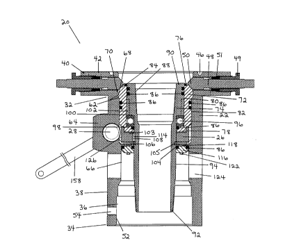
The apparatus (20) is comprised of a tubing head (22) and the functional
components of a tubing rotator. The functional components of the tubing rotator are
comprised of a swivel tubing hanger (24) and a drive gear (28) housed within thetubing head (22). The tubing hanger (24) is for connecting to the tubing string such that
the tubing string is rotatably suspended thereby. Further, the tubing hanger (24)
includes a driven gear (26) which is compatible with the drive gear (28) and is
releasably engagable therewith. Thus, the driven gear (26) and the drive gear (28)
comprise the drive system of the apparatus (20) which causes the tubing string
connected to the tubing hanger (24) to be rotated within the wellbore.
The tubing head (22) may be used in isolation where the tubing rotator
feature of the apparatus (20) is not required or desired by the operator of the well. In
this case, as shown in Figure 9, the tubing head (22) may be used with any conventional
non-swivel tubing hanger (30) compatible with the tubing head such that the tubing
hanger (30), and the connected tubing string, may be suspended within or by the tubing
head (22). In the event that the operator of the well subsequently desires to include a
tubing rotator within the wellhead structure, the tubing head (22) may be easily retrofit
to operate as a tubing rotator by the addition of the functional components of the
-10-
CA 02210239 1997-07-11
tubing rotator, being the swivel tubing hanger (24) and the drive gear (26) of the within
invention. The tubing head is easily retrofit in this manner because it is specifically
designed to accommodate these components in the event they are desired.
Referring to Figures 1-4 and 8-10, the tubing head (22) has an upper end
(32), a lower end (34), an internal bore (36) extending between the upper and lower ends
(32, 34) and an outer wall (38). The tubing head (22) may be of any shape or
configuration suitable for its intended function purpose as described herein. However,
the tubing head (22) is preferably tubular on cross section, as shown in Figures 4 and 10,
such that the circumference of the tubing head (22) defines the outer wall (38).
The upper end (32) of the tubing head (22) is preferably connectable to
other components of the wellhead or other wellhead equipment by any fastening orconnecting means, mechanism, structure or device suitable for temporarily fastening
or connecting the tubing head (22) to such other wellhead equipment. Thus, further
wellhead equipment may be mounted upon the tubing head (22) or the apparatus (20).
Specifically, the tubing head (22) is preferably connectable directly or indirectly to a
service blowout preventer so that a service blowout preventer may be mounted to the
tubing head (22) during servicing of the well without first requiring the moving of the
tubing string and without first requiring the removal of all or a portion of the tubing
head (22) or the apparatus (20). Although the connection is preferably a temporary
connection, permitting the removal of the other equipment, where required or desired
the connecting or fastening means may permit or cause a permanent connection
between the tubing head (22) and the other equipment.
In the preferred embodiment, the means for connecting the upper end
(32) of the tubing head (22) to other wellhead equipment is comprised of a tubing head
flange (40) located at the upper end (32) of the tubing head (22). As a result, the tubing
head flange (40) forms the uppermost surface of the tubing head (22) and the
uppermost surface of the apparatus (20). Further, in the preferred embodiment, the
tubing head flange (40) is integral with the remainder or balance of the tubing head
(22), and is thus continuous with the outer wall (38). Preferably, the tubing head (22) is
cast, machined or otherwise formed such that the tubing head flange (40) is
incorporated into or comprises the tubing head (22). However, alternately, the tubing
head flange (40) may comprise a separate or distinct portion of the tubing head (22),
which is connected to the upper end (32) of the tubing head (22) by any fastening or
connecting means, device, apparatus or mechanism suitable for fastening or
-11-
CA 02210239 1997-07-11
connecting the adjacent surfaces of the tubing head flange (40) and the tubing head (22).
In this instance, the connection is preferably permanent, however, the tubing head
flange (40) may be removably attached or connected to the upper end (32) of the tubing
head (22) where preferred or otherwise desirable to permit versatility or flexibility with
respect to the specific wellhead equipment which may be mounted upon the tubing
head flange (40).
As shown in Figures 1-3, 8 and 9, the tubing head flange (40) is preferably
comprised of an upper surface (42) on the upper end (32) of the tubing head (22), which
10 upper surface (42) is adapted for connection to the other wellhead equipment. Any
manner of adapting, or any structure, device or mechanism for adapting, the upper
surface (42) for connection to the other wellhead equipment may be used. However, in
the preferred embodiment, referring to Figure 1, the tubing head flange (40) is
comprised of the upper surface (42) defining at least two apertures (44), and preferably a
15 plurality of apertures (44), spaced circumferentially about the internal bore (36) of the
tubing head (22). The apertures (44) are for receiving fasteners, such as bolts, screws or
the like, therein such that the other wellhead equipment may be fastened to the tubing
head flange (40). Thus, the arrangement or configuration of the apertures (44) must be
compatible with the adjacent wellhead equipment to be mounted upon the tubing
20 head (22), and in particular, must be compatible with a flange or lowermost surface of
such equipment. Further, the upper surface (42) of the tubing head flange (42)
preferably defines an annular groove (46) about the circumference of the internal bore
(36), for receiving an O-ring or other seal, for sealing between the adjacent surfaces of
the tubing head flange (40) and the other wellhead equipment.
Preferably, the tubing head (22) is further comprised of any suitable
means, structure, device or mechanism capable of inhibiting the upward longitudinal
movement of the tubing hanger (24) relative to the tubing head (22), or movement in a
direction towards the upper end (32) of the tubing head (22), when it is contained
30 within the tubing head (22). In the preferred embodiment, referring to Figures 1-3, 8
and 9, the tubing head (22) includes at least one, and preferably two or more, adjustable
holddown screws (48), located adjacent the upper end (32) of the tubing head (22) for
inhibiting the relative movement of the tubing hanger (24) as discussed above. In
particular, the holddown screws (48) engage the tubing hanger (24) contained within
35 the internal bore (36) of the tubing head (22).
CA 02210239 1997-07-11
As described further below, each holddown screw (48) is adjustable such
that when the holddown screw (48) is adjusted for engagement with the tubing hanger
(24), longitudinal movement of the tubing hanger (24) supported within the internal
bore (36), relative to the tubing head (22) in the direction of the upper end (32) of the
5 tubing head (22), is inhibited. The holddown screws (48) are preferably located at or
adjacent to the upper end (32) of the tubing head (22). However, any other location
compatible with and suitable for the performance of their function or purpose asdescribed herein may be used. In any event, each holddown screw (48) extends to the
internal bore (36) of the tubing head (22) for engagement with the tubing hanger (24).
In the preferred embodiment, each holddown screw (48) extends through
the tubing head flange (40) through a bore from its outer surface to the internal bore
(36) of the tubing head (22). Further, in the preferred embodiment, the tubing head
flange (40) includes four holddown screws (48) spaced about equidistantly apart.15 However, any number of holddown screws (48) may be located in the tubing headflange (40), having either equidistant or non-equidistant spacing therebetween.
Further, the holddown screws (48) may be either symmetrically or non-symmetrically
placed about the tubing head flange (40).
Each holddown screw (48) extends through a packing nut (49), which is
held in place within the bore of the tubing head flange (40) by an outer threaded surface
of the packing nut (49) compatible with an inner threaded surface of the bore of the
tubing head flange (40). A nose (50) of each holddown screw (48) is similarly threaded
on its outer surface in order that it is held in place within the bore of the tubing head
flange (40) by the compatible inner threaded surface of the bore of the tubing head
flange (40). Packing (51) is located between the inner end of the packing nut (49) and
the nose (50) of the holddown screw (48).
The nose (50) of the holddown screw (48) is engagable with an outer
surface of the tubing hanger (24) when the tubing hanger (24) is suspended within the
tubing head (22). As described further below, the outer surface of the tubing hanger (24)
includes a compatible engagement surface for receiving the nose (50) of each holddown
screw (48). The holddown screws (48) are moveable within the bore of the tubing head
flange (40) such that the holddown screws (48) are adjustable in order that the nose (50)
may be moved into and out of engagement with the engagement surface as desired for
operation or servicing of the wellhead. When the holddown screws (48) are loosened
or moved away from the engagement surface, the tubing hanger (24) may be removed -13-
CA 02210239 1997-07-11
from the tubing head (22). Conversely, when the holddown screws (48) are tightened
and moved into engagement with the engagement surface, longitudinal movement of
the tubing hanger (24) relative to the tubing head (22) in the direction toward the upper
end (32) is inhibited.
Similarly, the lower end (34) of the tubing head (22) is preferably
connectable to the casing string, the casing head, an existing tubing head or any other
suitable components of the wellhead, or wellhead equipment. Thus, the tubing head
(22) is further comprised of means for mounting the tubing head (22) on the wellhead.
10 Any means, structure, device or mechanism suitable for mounting the tubing head (22)
to the particular wellhead structure may be used as long as it is compatible with the
function and purpose of the tubing head (22) and the apparatus (20). Further, the
mounting means may provide for either a temporary or a permanent connection
between the tubing head (22) and the wellhead structure to which it is attached. In the
15 preferred embodiment, the mounting means mount or connect the lower end (34) of
the tubing head (22) to the wellhead.
In the preferred embodiment, as shown in Figure 3, the lower end (34) of
the tubing head (22) is adapted to be connectable to, or capable of being mounted upon,
20 the casing string. Any manner, mechanism, structure or device for mounting the
lower end (34) to the casing string which is compatible with the function and purpose
of the tubing head (22) and the apparatus (20) may be used. However, preferably, the
mounting means is comprised of the internal bore (36) of the tubing head (22) defining
a mounting portion (52) adjacent to the lower end (34). The mounting portion (52) is
25 adapted for connection to the casing string. In the preferred embodiment, themounting portion (52) is sized and shaped to be compatible with the casing string so
that the upper end or free end of the casing string may snugly or closely fit within the
mounting portion (52) of the internal bore (36) of the tubing head (22).
Thus, to mount the tubing head (22), the mounting portion (52) is
positioned or fitted about the casing string such that the bore of the casing string is
continuous with the internal bore (36) of the tubing head (22). The tubing head (22)
may then be temporarily or permanently fastened to the casing string by any suitable
process, method, device, structure, mechanism or means for fastening the adjacent
surfaces. However, preferably, the mounting portion (52) of the internal bore (36) is
welded to the casing string. For this reason, the preferred embodiment of the tubing
head (22), as shown in Figure 3, includes a weld grease test port (54) adjacent the lower
-14-
CA 02210239 1997-07-11
end (34) which extends from the outer wall (38) to the internal bore (36). The weld
grease test port (54) is used to test the effectiveness of the weld.
Referring to Figure 8, alternately, the lower end (34) of the tubing head
5 (22) may be adapted to be connectable to, or capable of being mounted upon, a casing
bowl or casing head or an existing tubing head already present on the wellhead. In
particular, conventional casing heads and conventional tubing heads are comprised of
a flange, and the lower end (34) is connectable to the casing head or tubing head flange.
Any manner, means, mechanism, structure or device for mounting or fastening the
10 lower end (34) to the casing head or tubing head flange, which is compatible with the
function and purpose of the tubing head (22) and the apparatus (20), may be used.
Again, the mounting means may provide for either a temporary or a permanent
connection as desired by the operator of the well.
In the preferred alternate embodiment, as shown in Figure 8, the
mounting means is comprised of a lower surface (56) on the lower end (34) of thetubing head (22), which lower surface (56) is adapted for connection to the casing head
or existing tubing head, and preferably, the casing head or tubing head flange. Any
manner of adapting, or any structure, means, device or mechanism for adapting, the
20 lower surface (56) for connection to the casing head or tubing head flange may be used.
However, in the preferred alternate embodiment, the lower surface (56) comprises a
mounting flange (57) which defines at least two apertures (58), and preferably aplurality of apertures (58), circumferentially spaced about the mounting flange (57) at
the lower surface (56). The apertures (58) are for receiving fasteners, such as bolts,
25 screws or the like, therein. The apertures (58) are arranged or configured on the lower
surface (56) to be compatible with the casing head or tubing head flange.
In the preferred alternate embodiment, to mount the tubing head (22), the
mounting flange (57) is positioned on the casing head flange or the existing tubing
30 head flange such that the apertures (58) in the lower surface (56) are aligned with the
apertures in the casing head or tubing head flange. As a result, the bore of the casing
head or the existing tubing head is aligned with the internal bore (36) of the tubing
head (22). The fastener, being a stud bolt, is then screwed into the apertures (58) in the
lower surface (56). When mounted, the fasteners extend from the apertures (58) in the
35 lower surface (56), through compatible apertures defined by the casing head or tubing
head flange. A nut is then screwed onto the end of the fastener to secure the mounting
flange (57), and thus the tubing head (22, upon the casing head or existing tubing head.
-15-
CA 02210239 1997-07-11
Finally, referring to Figure 8 of the alternate embodiment, the lower
surface (56) of the tubing head (22) preferably defines an annular groove (60) about the
circumference of the lower surface (56), for receiving an O-ring or other seal, for sealing
5 between the adjacent surfaces of the mounting flange (57) and the casing head or tubing
head flange.
In addition, the internal bore (36) of the tubing head (22) defines an
internal surface (62) for engagement with the tubing hanger (24) such that the tubing
hanger (24) is suspended by the internal surface (62) within the internal bore (36). As
well, the tubing head (22) further defines a gear housing (64) which communicates
with the internal bore (36) and which is capable of accommodating and containing the
drive gear (28) therein. As described in further detail below, the internal surface (62)
defined by the internal bore (36), the gear housing (64), the drive gear (28) and the
15 driven gear (26) are all configured such that when the drive gear (28) is contained
within the gear housing (64), the tubing hanger (24) is located in the internal bore (36)
and the driven gear (26) is engaging the drive gear (28), the tubing hanger (24) is capable
of being removed from the internal bore (36) by pulling it through the upper end (32)
of the tubing head (22) without first disengaging the drive gear (28) from the driven
20 gear (26).
In other words, once the holddown screws (48) are released from
engagement with the tubing hanger (24), the tubing hanger (24) may be lifted
longitudinally upwards through the upper end (32) without requiring the removal or
25 adjustment of any of the other components of the tubing head (22) or the apparatus
(20). In particular, the removal of the tubing hanger (24) does not require the removal
or adjustment or repositioning of any of the elements comprising the drive system,
being the drive gear (28) and the driven gear (26). The same considerations apply to the
placement of the tubing hanger (24) into the tubing head (22). As stated, this result is
30 achieved by the specific configuration of the internal bore (36), including the internal
surface (62), and the gear housing (64) in the within invention. In addition, the tubing
hanger (24) and the drive system are compatible with the achievement of this function
or purpose.
Further, in the preferred embodiment, the tubing head (22) and the
compatible tubing hanger (24) are configured such that when a service blowout
preventer is mounted on the upper end (32) of the tubing head (22) and the tubing
-16-
CA 02210239 1997-07-11
hanger (24) is located in the internal bore (36), the tubing hanger (24) may be removed
from the internal bore (36) by pulling it through the blowout preventer in order to
service the well. As the blowout preventer may be mounted to the upper end (32)
without requiring the removal of any of the components of the tubing head (22) or the
apparatus (20), including the holddown screws (48), the position of the tubing string
connected to the tubing hanger (24) is maintained in the wellbore. Thus, the
likelihood of a blowout during the mounting process is minimized. Once the blowout
preventer is mounted, the holddown screws (48) may be released and the tubing
hanger (24), along with the connected tubing string, may be safely removed through
10 the blowout preventer.
In particular, in the preferred embodiment, the internal bore (36) has a
minimum and a maximum diameter. A portion of the internal bore (36) defines a
minimum diameter (66) of the internal bore (36). In the preferred embodiment, the
15 gear housing (64) is configured such that when the drive gear (28) is housed or
contained within the gear housing (64), the drive gear (28) does not extend beyond the
minimum diameter (66). In other words, the drive gear (28) does not protrude into the
internal bore (36) within the minimum diameter (66) of the internal bore (36). The
minimum diameter (66) of the internal bore (36) is determined by the specifications set
20 by the American Petroleum Institute for any particular size of the tubing head (22) or
the apparatus (20), and in particular by API Specification 6A (SPEC 6A) entitled"Specification for Wellhead and Christmas Tree Equipment". For instance, the
minimum diameter (66) for the internal bore (36) for a 7 1/16 inches diameter tubing
head (22) is specified as 6.45 inches. Thus, the drive gear (28) does not encroach into the
25 6.45 inches diameter boundary.
As stated, the internal surface (62) defined by the bore (36) engages the
tubing hanger (24) such that the tubing hanger (24) is suspended thereby. Any
configuration of the engaged surfaces of the tubing head (22) and the tubing hanger
30 (24), and any manner of engagement, may be used which permits the tubing hanger
(24) to be suspended within the internal bore (36) by the tubing head (22). Moreparticularly, the internal surface (62) of the internal bore (36) and the corresponding
external surface (68) of the tubing hanger (24), described further below, are preferably
shaped to be compatible in order to facilitate the seating of the external surface (68) of
35 the tubing hanger (24) on the internal surface (62) such that the external surface (68) is
supported thereby. The specific shape of the seating arrangement between the internal
and external surfaces (62, 68) may vary from the internal surface (62) having a gradual
-17-
CA 02210239 1997-11-12
angled slope through its length to the internal surface (62) having a vertical portion
and a protruding horizontal or sloped shoulder portion. As shown in Figure 3, in the
preferred embodiment, the internal surface (62) which engages the tubing hanger (24) is
comprised of a shoulder for seating and supporting the tubing hanger (24) thereon.
A portion of the internal bore (36) of the tubing head (22) also defines a
maximum diameter (70) of the internal bore (36). In particular, in the preferredembodiment, the internal surface (62) defines the maximum diameter (70) of the
internal bore (36). Further, the maximum diameter (70) of the internal bore (36) is
10 preferably only slightly greater than the maximum diameter of the tubing hanger (24)
so that a close fit and sealing engagement may be achieved therebetween. In other
words, the maximum diameter (70) of the internal bore (36) is about equal to themaximum diameter of the tubing hanger (24).
The maximum diameter of the tubing hanger (24) is determined by the
specifications set by the American Petroleum Institute for any particular size of the
tubing hanger (24), and in particular by API Specification 6A (SPEC 6A) entitled"Specification for Wellhead and Christmas Tree Equipment". In particular, the
maximum diameter (70) is determined by the maximum permissible diameter of the
tubing hanger (24) which permits or allows that tubing hanger (24) to be run or pulled
through a service blowout preventer. For instance, the maximum permissible
diameter of the tubing hanger (24), for a 7 1/16 inches diameter tubing head (22), which
permits it to be pulled thorough a blowout preventer is 7.010 inches. Thus, the
maximum diameter (70) of the internal bore (36) is slightly greater than, or about, 7.010
inches.
The difference between the minimum diameter (66) and the maximum
diameter (70) provides a space or area which must accommodate the internal surface
(62), comprising the shoulder in the preferred embodiment. In addition, the space or
area between the minimum and maximum diameters (66, 70) must also accommodate
a meshing between the drive gear (28) and the driven gear (26). Specifically, the drive
gear (28) and the driven gear (26) engage each other between the minimum diameter
(66) and the maximum diameter (70). In the preferred embodiment, utilizing a 7 1/16
inches diameter tubing head (22), the difference between the minimum and maximumdiameters (66, 70) provides a space of 0.56 inches. The relative use of this space for the
accommodation of the internal surface (62) and the meshing of the gears may be varied
as required or desired. However, the relative use of this space must provide a
-18-
CA 02210239 1997-11-12
sufficient internal surface (62) to permit the internal surface (62) to effectively engage
the tubing hanger (24) such that it may be suspended within the internal bore (36) by
the internal surface (62). In addition, the relative use of this space must provide or
allow for a sufficient meshing between the drive gear (28) and the driven gear (26) such
5 that the drive gear (28) may effectively engage the driven gear (26). In the preferred
embodiment, the internal surface (62), and in particular the shoulder thereof, utilizes
0.13 inches of the total 0.56 inches diameter difference and the meshing of the gears,
and in particular the protrusion of the drive gear (28) into the internal bore (36) utilizes
0.43 inches of the total 0.56 inches diameter difference.
Specific dimensions for tubing heads (22) of varying sizes, such as a 9 or 11
inches diameter tubing head, may be designed in the same manner and using the same
principles as described above for the 7 1/16 inches diameter tubing head (22).
As stated, the apparatus (20) is further comprised of the swivel tubing
hanger (24) for locating within the internal bore (36) of the tubing head (22) and for
connecting to the tubing string. Any swivel tubing hanger (24) compatible with its use
within the tubing head (22) and which permits the functioning of the apparatus (20) as
described herein may be used. Preferably, the tubing hanger (24) is comprised of the
driven gear (26) and the external surface (68) for engaging the internal surface (62) of
the tubing head (22) such that the tubing hanger (24) may be suspended by the tubing
head (22). In the preferred embodiment of the apparatus (20), the tubing hanger (24) is
further comprised of a supporting member (72) and a supported member (74) rotatably
supported within the supporting member (72).
The supporting member (72) preferably comprises the external surface
(68). Thus, the internal surface (62) of the tubing head (22) engages the external surface
(68) of the supporting member (72). The supporting member (72) may be comprised of
any members, elements, structure, device, apparatus or mechanism suitable for
rotatably supporting the supported member (74) such that the tubing string connected
to the supported member (74) may be rotatably supported within the wellbore. Further,
the external surface (68) of the supporting member (72) may engage the internal surface
(62) in any suitable manner permitting the supporting member (72) to be supported
thereby and to perform its intended function. As well, the supporting member (72)
may rotatably support the supported member (74) in any manner or by any means ormechanism suitable for performing this intended function.
-19-
CA 02210239 1997-07-11
In the preferred embodiment, the supporting member (72) is tubular to
rotatably support the supported member (74) therein and includes an upper end (76), a
lower end (78), an inside surface (80) and on outside surface (82). The outside surface
(82) of the supporting member (72) is comprised of the external surface (68). In the
5 preferred embodiment, the external surface (68) defines the maximum diameter of the
tubing hanger (24), which is about equal to the maximum diameter (70) of the internal
bore (36).
Although the location of the external surface (68) may vary, the external
10 surface (68) is preferably positioned at, adjacent or in proximity to the upper end (76) of
the supporting member (72). Thus, when the supporting member (72) is contained
within the tubing head (22), the upper end (76) of the supporting member (72) is located
within the internal bore (36) adjacent the upper end (32) of the tubing head (22), while
the lower end (78) of the supporting member (72) extends within the internal bore (36)
15 towards the lower end (34) of the tubing head (22). The shape or configuration of the
external surface (68) is compatible with the shape or configuration of the internal
surface (62) such that the external surface (68) may be seated upon and suspended by the
internal surface (62). Thus, in the preferred embodiment, in which the internal surface
(62) is comprised of a shoulder, the external surface (68) is similar comprised of a
20 compatible shoulder.
Further, the upper end (76) of the supporting member (72) defines a
holddown screw engagement surface (84) which is compatible with the nose (50) of the
holddown screw (48). Thus, upon adjustment of the holddown screw (48), the nose
25 (50) may be moved into and out of engagement with the engagement surface (84) as
desired for operation or servicing of the wellhead.
Finally, preferably, the adjacent surfaces of the internal bore (36) of the
tubing head (22) and the outside surface (82) of the supporting member (72) are sealed
30 by a sealing assembly. Any suitable sealing assembly may be used. However, in the
preferred embodiment, the sealing assembly is comprised of the outside surface (82) of
the supporting member (72) defining at least one annular groove, and preferably two,
about the circumference or perimeter of the supporting member (72), for receiving an
O-ring (86), polypak seal or other suitable seal.
Preferably, the supported member (74) is tubular such that a bore (88) of
the supported member (74) permits the passage of the rod string and wellbore fluids
-20-
CA 02210239 1997-07-11
therethrough. Further, the supported member (74) includes an upper end (90), a lower
end (92) and an outside surface (94). The outside surface (94) of the supported member
(74) preferably sealingly engages the inside surface (80) of the supporting member (72).
The adjacent surfaces are sealingly engaged by a sealing assembly. Any suitable sealing
5 assembly may be used. However, in the preferred embodiment, the sealing assembly is
comprised of either or both of the inside surface (80) of the supporting member (72) and
the outside surface (94) of the supported member (74) defining at least one annular
groove, and preferably two or more, about the circumference or perimeter of suchsurfaces (80, 94), for receiving an O-ring (86), polypak seal or other suitable seal.
The upper end (90) of the supported member (74) is preferably positioned
adjacent the upper end (76) of the supporting member (72). The bore (88) of the
supported member (74) is preferably threaded for connection to a tool during theservicing of the well in order to facilitate the removal of the tubing hanger (24). The
lower end (92) of the supported member (74) extends through the lower end (78) of the
supporting member (72). As shown in Figures 3 and 8, the lower end (92) may or may
not extend through the lower end (34) of the tubing head (22). Further, the outside
surface (94) of the supported member (74) adjacent the lower end (92) is threaded such
that the tubing string may be connected thereto by a tubing connector or like
mechanism.
As indicated, the supported member (74) is rotatably supported by the
supporting member (72) such that the longitudinal movement of the of the supported
member (74) relative to the supporting member (72) in a direction towards the lower
end (34) of the tubing head (22) is inhibited. Any means, mechanism, device or
structure capable of supporting the supported member (74) in the required mannerwhich is compatible with the function of the tubing hanger (24), may be used.
However, preferably, the supported member (74) is rotatably supported within thesupporting member (72) by at least one bearing (96) located between the supported
member (74) and the supporting member (72) such that the bearing (96) is seated on the
supporting member (72) and the supported member (74) is rotatably supported uponthe bearing (96). Any bearing (96) suitable for, and compatible with, this intended
purpose or function may be used. For instance, the bearing (96) may be comprised of a
thrust bearing, a radial bearing, a tapered roller bearing or a combination thereof.
In the preferred embodiment, the inside surface (80) of the supporting
member (72) includes a shoulder (98) which extends inwardly towards the supported
-21-
CA 02210239 1997-07-11
member (74). The bearing (96) is seated on the shoulder (98). A compatible shoulder
(100) on the outside surface (94) of the supported member (74) is then seated on the
bearing (96) such that the supported member (74) is rotatably supported upon thesupporting member (72). In this manner, the downward longitudinal movement of
the supported member (74) relative to the supporting member (72) is inhibited. In the
preferred embodiment, the bearing (96) is comprised of a thrust bearing in combination
with a bushing sleeve (102) which acts as a radial bearing. The bushing sleeve (102) is
also located between the supported member (74) and the supporting member (72),
preferably above the thrust bearing.
Further, the supported member (74) is associated with the driven gear (26)
such that rotation of the driven gear (26) causes the supported member (74) to rotate
within the supporting member (72). Any structure, device, mechanism or means forassociating the supported member (74) and the driven gear (26) in the described
15 manner may be used. However, in the preferred embodiment, the driven gear (26) is
fixedly mounted or connected about the outside surface (94) of the supported member
(74) such that the driven gear (26) extends from the supported member (74) towards the
gear housing (64) defined by the tubing head (22) for engagement with the drive gear
(28). Thus, the driven gear (26) is preferably located along the supported member (74) at
20 a position such that the driven gear (26) is adjacent to the drive gear (28) when the
tubing hanger (24) is located within the internal bore (36) of the tubing head (22).
In the preferred embodiment, the driven gear (26) is located about the
supported member (74) such that an upper surface (103) of the driven gear (26) is
25 adjacent the lower end (78) of the supporting member (72). The driven gear (26) may be
mounted or otherwise fastened to the supported member (74) by any suitable means,
structure, device or mechanism for mounting or fastening the driven gear (26) thereto.
However, in the preferred embodiment, as shown in Figures 3 and 5-7, the driven gear
(26) defines a plurality of threaded apertures (104) for the passage of a set screw (106) or
30 similar fastener therethrough. Non-threaded apertures (105), compatible with the
apertures (104) in the driven gear (26), are defined by the outside surface (94) of the
supported member (74) for receiving an end of the set screws (106) therein. As well, an
inside surface (108) of the driven gear (26) defines a keyway (110), as shown in Figures
3-5, which is compatible with a keyway (112) defined by the adjacent outside surface (94)
35 of the supported member (74). Alignment of the keyways (110, 112) and the set screw
apertures (104, 105), and the insertion of a key (114) and the set screws (106) respectively
CA 02210239 1997-07-11
therein, facilitates in the proper or correct positioning of the driven gear (26) on the
supported member (74).
In addition, the tubing hanger (24) further preferably comprises means for
5 inhibiting the longitudinal movement of the supported member (74) relative to the
supporting member (72) in a direction toward the upper end (32) of the tubing head
(22). Any means, mechanism, structure or device capable of performing this function
may be used, For instance, the inhibiting means may be comprised of a retaining ring
or similar structure for securing the supported member (74) to the supporting member
10 (72). However, in the preferred embodiment, the inhibiting means is comprised of the
abutment of the driven gear (26) and the supporting member (72). More particularly,
the uppermost surface of the driven gear (26) abuts the lower end (78) of the supporting
member (72).
Finally, in the preferred embodiment, the tubing hanger (24) is further
comprised of a bronze sealing retainer (116) which also provides a side load bearing
surface. Referring to Figures 3 and 5-7, the sealing retainer (116) is mounted to a lower
surface (118) of the driven gear (26). More particularly, the driven gear defines a
plurality of threaded apertures (120) which extend from the lower surface (118) of the
driven gear (26) towards the upper surface (103). The sealing retainer (116) defines a
plurality of threaded apertures compatible with the threaded apertures (120) of the
driven gear (26). Thus, the sealing retainer (116) may be positioned adjacent the lower
surface (118) of the driven gear (26) and connected thereto by the passage of a fastener
(122) through the compatible apertures in the sealing retainer (116) and the driven gear
(26). Any suitable fastener (122) may be used, however, the fastener (122) is preferably a
screw.
Preferably, the surface of the sealing retainer (116) adjacent the lower
surface (118) of the driven gear (26) includes a sealing assembly. Any suitable sealing
assembly may be used. However, in the preferred embodiment, the sealing assembly is
comprised of the uppermost surface of the sealing retainer (116), adjacent the lower
surface (118) of the driven gear (26), defining at least one annular groove about each of
the inner and outer circumferences or perimeters of such surface for receiving an O-
ring (86), polypak seal or other suitable seal. Alternately, the sealing retainer (116) may
be an integral part of the driven gear (26), which defines the annular grooves for the
seals.
CA 02210239 1997-07-11
In the preferred embodiment shown in Figure 3, the tubing head (22) also
further defines at least one annular vent (124). The annular vent (124) permits the
venting or production of any fluids from the wellbore through the tubing head (22).
Alternately, the annular vent (124) permits fluids to be directed into the wellbore
5 through the tubing head (22). Preferably, each annular vent (124) extends from the
outer wall (38) of the tubing head (22) to the internal bore (36). Further, the vents (124)
are preferably located such that the vent (124) communicates with the internal bore (36)
at a location such that when the tubing hanger (24) is located in the tubing head (22),
the annular vent (124) is positioned between the sealing retainer (116) and the lower
end (34) of the tubing head (22). However, the vent (124) must not be located such that
it interferes with the mounting of the tubing head (22) on the casing string.
As stated, the drive system of the apparatus (20) is comprised of the drive
gear (28) and the driven gear (26). The drive gear (28) is of a type and configuration
15 which is able to be accommodated or contained within the gear housing (64) and which
is compatible with the driven gear (26) such that the drive gear (28) may releasably
engage the driven gear (26) when the tubing hanger (24) is located within the internal
bore (36). Further, the drive gear (28) is of a type and configuration such that it does not
protrude into the internal bore (36) within the minimum diameter (66) of the internal
20 bore (36). The driven gear (26) is also of a type and configuration which is able to be
accommodated or contained within the internal bore (36) of the tubing head (22) and
which is compatible with the driven gear (26) such that the driven gear (26) mayreleasably engage the drive gear (28) when the tubing hanger (24) is located within the
internal bore (36). The driven gear (26) is also of a type and configuration capable of
25 being associated with the tubing hanger (24), and in particular the supported member
(74) such that rotation of the driven gear (26) causes the supported member (74) to
rotate within the supporting member (72).
The drive gear (28) and the driven gear (26) may be comprised of any gears
30 capable of performing the functions or purposes set out above, and which permit the
drive gear (28) and the driven gear (26) to engage each other between the minimum
diameter (66) and the maximum diameter (70) of the internal bore (36). However,
preferably, the drive gear (28) is comprised of a worm and the driven gear (26) is
comprised of a worm gear. Any suitable worm (28) and worm gear (28) may be used.35 For instance, a cylindrical worm (28) may mesh with a enveloped worm gear (26) to
form a single enveloping type of wormgear drive system. Alternately, the worm (28)
and the worm gear (26) may both be enveloping to form a double enveloping type of
-24-
CA 02210239 1997-07-11
wormgear drive system. However, in the preferred embodiment, the worm (28) and
the worm gear (26) are both non-enveloping in order to facilitate the removal of the
tubing hanger from the internal bore without first disengaging the worm (28) from the
worm gear (26).
Further, where a worm (28) and worm gear (26) are used, the worm (28)
and worm gear (26) facilitate the connection of a servicing tool to the tubing hanger
(24), and thus the removal of the tubing hanger (24) from the internal bore (36) of the
tubing head (22), during servicing of the well. In particular, as the drive system is not
10 first disengaged in order to service the well, the engagement between the worm (28)
and the worm gear (26) inhibit any undesirable rotation of the supported member (74)
during the connection of the servicing tool to the upper end (90) of the supported
member (74) within the threaded bore (88).
Referring to Figures 4-7, the worm gear (26) is tubular for mounting about
the supported member (74), as described above, and is preferably circular on cross
section. In the preferred embodiment, each tooth (126) on the worm gear (26), located
about the circumference of the worm gear (26), extends from an upper end (128),
adjacent the upper surface (103) of the worm gear (26) towards the lower surface (118) of
the worm gear (26) to a lower end (130). In the preferred embodiment, referring to
Figure 6, when viewed from the top face (131) of the tooth, the opposing sides (132) of
the tooth (126), adjacent the lower end (130), are preferably tapered inwardly towards
the centre of the tooth (126) in order to facilitate the feeding of the worm gear (26) onto
the worm (28). In addition, in the preferred embodiment, referring to Figure 6, when
viewed from the side (132) of the tooth (126), the tooth (126) is sloped downwardly,
adjacent the lower end (130) of the tooth (126), from the top face (131) to the bottom face
(134) in order to facilitate the feeding of the tubing hanger (24) into the internal bore
(36) of the tubing head (22). Otherwise, the teeth (126) are shaped or configured to be
compatible with the worm (28) such that a desired degree of meshing, contact or
engagement occurs therebetween.
In the preferred embodiment, the worm gear (26) for a 7 1/16 inches
diameter tubing head (22) has the following specifications: a diametral pitch of 8; a
single left hand thread; a pitch diameter of 6.625 inches; 53 teeth (126); a lead of .3927
inches; a lead angle of 4 degrees 46'; a pressure angle of 14 1/2 degrees; and a centre
distance of 4.0625 inches. As well, the worm gear (26) is preferably comprised of
-25-
CA 02210239 1997-07-11
manganese bronze C86300, which reduces the galling of the teeth (126) under heavy
loads.
Referring to Figures 3 and 4, in the preferred embodiment, the worm (28)
is comprised of a worm shaft (136), which is preferably circular on cross section, and
worm teeth (137) located about the circumference of the worm shaft (136) for a portion
of the length of the worm shaft (136). Further, the worm shaft (136) has a first end (138)
and a second end (140). The worm (28), and in particular the worm shaft (136), is
rotatably supported within the gear housing (64) such that the worm shaft (136) may
10 rotate about its longitudinal axis and such that the worm teeth (137) are positioned to
engage the worm gear teeth (126) so that rotation of the worm shaft (136) causesrotation of the worm gear (26). The worm teeth (137) are shaped or configured to be
compatible with the worm gear teeth (126) such that a desired degree of meshing,contact or engagement occurs therebetween. In addition, as shown in Figure 4, the
15 crest of the worm teeth (137) may be reduced where necessary to avoid the protrusion
of the worm teeth (137) into the minimum diameter (66) of the internal bore (36).
Also, the crest of the worm teeth (137) are preferably tapered to facilitate the feeding of
the worm gear (26) into the worm (28). In the preferred embodiment, the worm (28) is
comprised of a hardened and polished alloy steel.
The worm (28), and more particularly the worm shaft (136) may be
rotatably supported within the gear housing (64) by any means, mechanism, structure
or device suitable for, and capable of, supporting the worm shaft (136) in the desired
manner such that the worm (28) may perform its function or purpose as described
25 herein. In the preferred embodiment, the gear housing (64) is comprised of a first end
(142) and a second end (144). The first end (138) of the worm shaft (136) is positioned
within the gear housing (64) adjacent the first end (142) of the gear housing (64). The
second end (140) of the worm shaft (136) extends through and beyond the second end
(144) of the gear housing (64). Although the ends (142, 144) of the gear housing (64)
30 may be integral with the remainder of the gear housing (64) defined by the tubing head
(22), in the preferred embodiment, the first and second ends (142, 144) are removable
therefrom in order to facilitate the mounting and maintenance of the worm (28).
In particular, in the preferred embodiment, the first and second ends (142,
35 144) of the gear housing (64) are each comprised of a bearing retainer (146) threaded
within, or otherwise fastened to, the gear housing (64). For instance, the bearing
retainer (146) may be fastened to the gear housing (64) using a lock nut (147). Each
bearing retainer (146) may define a grease ~sage (148) extending from an outer surface
CA 02210239 1997-07-11
to an inner surface of the bearing retainer (146) such that grease may be inserted
therethrough. Further, each grease passage (148) includes a grease fitting (150) for
sealing the grease passage (148) adjacent the outer surface of the bearing retainer (146).
Finally, the bearing retainer (146) at the second end (144) of the gear housing (64)
defines an opening for passage of the second end (140) of the worm shaft (136)
therethrough such that the second end (140) of the worm shaft (136) is outside of the
gear housing (64). Where the second end (140) of the worm shaft (136) exits the bearing
retainer (146), the opening in the bearing retainer (146) preferably defines at least one
annular groove for receiving a rod wiper (151) or the like therein.
One or more bearings (152) are mounted adjacent the inner surfaces of
each bearing retainer (146), which bearings (152) rotatably support the worm shaft (136)
which extends therethrough. Any bearing (152) suitable for, and compatible with, this
intended purpose or function may be used. For instance, the bearing (152) may be15 comprised of a thrust bearing, a radial bearing, a tapered roller bearing or a
combination thereof. The bearings (152) are located between, and maintained in
position by, the adjacent bearing retainer (146) and a shoulder (154) on the worm shaft
(136). Preferably, a sealing assembly is associated with each shoulder (154) for sealing
the bearings (152) such that fluids and grease are unable to pass between the bearings
20 (152) and the portion of the gear housing (64) containing the worm teeth (137). Any
suitable sealing assembly may be used. However, in the preferred embodiment, thesealing assembly is comprised of one or more O-rings (86), polypak seals or other
suitable seals.
Finally, the worm (28) is further comprised of means for driving or
operating the worm (28) such that the worm (28) drives the worm gear (26). Any
means, mechanism, structure or device suitable for, and capable of, driving or
operating the worm (28) in the described manner may be used. Preferably, the driving
structure or mechanism is more particularly comprised of means for rotating the
30 worm shaft (136). Any means, mechanism, structure or device suitable for, and capable
of, rotating the worm shaft (136) about its longitudinal axis may be used. The rotating
structure or mechanism may be operated manually or by any other drive motor or
mechanism.
Preferably, the worm shaft (136) is rotated manually. A ratchet and pawl
assembly (156), or a like mechanism, is operably mounted or connected to the second
end (140) of the worm shaft (136). In the preferred embodiment, the ratchet and pawl
-27-
CA 02210239 1997-07-11
assembly is comprised of a sprage clutch. Further, the ratchet and pawl assemblyincludes a drive handle (158) such that movement of the drive handle (158) causes
rotation of the worm shaft (136).
-28-