Note: Descriptions are shown in the official language in which they were submitted.
CA 02210401 1997-07-14
PISTON FOR COMPRESSORS
BACKGROUND OF THE INVENTION
1. FIELD OF THE INVENTION
The present invention relates to piston type
compressors that convert rotation of a rotary shaft to
linear reciprocation of a piston with a driving body such as
a swash plate, and more particularly, to pistons used in
such compressors.
2. DESCRIPTION OF THE RELATED ART
Compressors are employed in air-conditioning systems
for vehicles. Piston type compressors are used in such
systems. A typical piston type compressor is provided with
a driving body, such as a swash plate, to reciprocate
pistons. The swash plate is supported by a drive shaft in a
crank chamber and converts the rotation of the drive shaft
to the linear reciprocation of each piston in an associated
cylinder bore. The reciprocation of the piston draws
refrigerant gas into the cylinder bore from a suction
chamber, compresses the gas in the cylinder bore, and
discharges the gas into a discharge chamber.
The typical piston type compressor draws the
refrigerant gas from an external refrigerant circuit into a
suction chamber by way of the crank chamber. In such a
compressor, in which the crank chamber constitutes a portion
of a refrigerant gas passage, the refrigerant gas from the
external refrigerant circuit passing through the crank
chamber sufficiently lubricates various parts in the crank
-1-
CA 02210401 1997-07-14
chamber, such as the piston and the swash plate, with the
lubricating oil suspended in the gas.
There is also a type of compressor that draws in
refrigerant gas from an external refrigerant circuit without
having the gas flow through its crank chamber. In such a
compressor, the driving plate, or swash plate, is supported
so that it inclines with respect to the drive shaft. The
inclination of the swash plate changes in accordance with
the difference between the pressure in the crank chamber and
the pressure in the cylinder bores. The displacement of the
compressor varies in accordance with the inclination of the
swash plate. The difference between the pressure in the
crank chamber and the pressure in the cylinder bores is
changed, for example, by adjusting the pressure in the crank
chamber using a control valve. Since the pressure of the
crank chamber is adjusted to control the inclination of the
swash plate in such type of compressor, the crank chamber is
not included in the suction passage. Therefore, the various
parts in the crank chamber are lubricated mainly by
lubricating oil that is included in blowby gas. Blowby gas
refers to the refrigerant gas in the cylinder bore that
leaks into the crank chamber through the space defined
between the outer surface of the piston and the wall of the
associated cylinder bore when the piston compresses the
refrigerant gas in the cylinder bore.
The amount of blowby gas, or lubricating oil, supplied
to the crank chamber is determined by the dimension of the
clearance defined between the outer surface of the piston
and the wall of the cylinder bore. Accordingly, it is
necessary to increase the dimension of the clearance to
supply a sufficient amount of lubricating oil for
-2-
CA 02210401 1997-07-14
satisfactory lubrication of the various parts in the crank
chamber. However, a large clearance between the piston and
the cylinder bore degrades the compressing efficiency of the
compressor.
To cope with this problem, compressors such as that
shown in Fig. 8 are known in the prior art. The compressor
has a swash plate 100. The swash plate 100 is mounted on a
drive shaft 104 in a crank chamber 103, which is provided
between the cylinder block 101 and the front housing 102,
and supported so as to rotate integrally with the shaft 104.
Single-headed pistons 105 are each accommodated in a
cylinder bore lOla, which is provided in the cylinder block
101. A skirt 105a projects from the rear side of each
piston 105 (to the left as viewed in Fig. 8) toward the
crank chamber 103. The skirt 105a is operably connected to
the swash plate 100 by a pair of shoes 106. Each shoe 106
is slidably clamped between the skirt 105a and the swash
plate 100. The rotation of the drive shaft 104 is converted
to the linear reciprocation of the piston 105 in the
cylinder bore lOla by means of the swash plate 100 and the
shoes 106.
An annular groove 107 extends along the outer surface
of each piston 105. Lubricating oil applied to the wall of
the cylinder bore lOla is collected in the groove 107 and
guided toward the crank chamber 103 during reciprocation of
the piston 105. The lubricating oil lubricates the
connecting portion between the swash plate 100 and the
piston 105. Accordingly, in compressors that employ pistons
having such structure, the various parts in the crank
chamber may be satisfactorily lubricated without enlarging
the dimension of the clearance between the piston and the
-3-
CA 02210401 1997-07-14
cylinder bore, or without reducing the compressing
efficiency of the compressor.
As shown in Figs. 8 and 9, the skirt 105a of the piston
105 has an arched surface 105b, which is defined on the
surface facing the inner surface of the front housing 102.
The arched surface 105b slides against the inner surface of
the front housing 102. The radius of curvature of the
arched surface 105b is the same as that of the inner surface
of the front housing 102. When the piston 105 reciprocates,
the arched surface 105b slides against the inner surface of
the front housing 102 and prevents the piston 105 from
rotating about its axis.
The arched surface 105b extends along the entire width
of the skirt 105a that faces the inner surface of the front
housing 102. However, it is difficult to accurately machine
the entire arched surface 105b so that it has the same
radius of curvature as the inner surface of the front
housing 102.
Furthermore, the entire arched surface 105b, which
extends for a wide range, slides against the inner surface
of the front housing 102. Thus, when the piston 105 moves
from the top dead center position to the bottom dead center
position, the lubricating oil on the end face of the skirt
105a and the lubricating oil that collects at the bottom of
the crank chamber 103 is dispersed toward the left, as
viewed in Fig. 8. The lubricating oil is not guided to the
connecting portion between the piston 105 and the swash
plate 100. Accordingly, this oil is not used efficiently,
and the connecting portions between the pistons 105 and the
swash plate 100 are not lubricated to the degree that is
-4-
CA 02210401 1997-07-14
desirable.
SUMMARY OF THE INVENTION
Accordingly, it is an objective of the present
invention to provide a compressor piston that facilitates
machining and effectively lubricates the joints connecting
the pistons to the driving body with the lubricating oil
from the crank chamber.
To achieve the above objective, the present invention
discloses a piston for use in a compressor that compresses
gas containing lubricating oil. The compressor includes a
housing having a crank chamber and a cylinder bore for
accommodating the piston. The housing has an inner surface
for defining the crank chamber. A driving body is located in
the crank chamber. The driving body is operably connected
to the piston by a connecting joint. The driving body
reciprocates the piston between a top dead center position
and a bottom dead center position by means of the connecting
joint. The piston has a head for compressing the gas
supplied to the cylinder bore, a skirt projecting from the
head toward the crank chamber and connected to the driving
body. A restrictor is provided on the skirt to prevent the
piston from rotating in the cylinder bore. The restrictor
has a plurality of sliding portions slidably contacting the
inner surface of the housing. Each sliding portion is spaced
from one another by a predetermined distance to form a
passage for lubricating oil between the sliding portions.
BRIEF DESCRIPTION OF THE DRAWINGS
The features of the present invention that are believed
-5-
CA 02210401 1997-07-14
to be novel are set forth with particularity in the appended
claims. The invention, together with objects and advantages
thereof, may best be understood by reference to the
following description of the presently preferred embodiments
together with the accompanying drawings in which:
Fig. 1 is a cross-sectional view showing a compressor
employing pistons according to a first embodiment of the
present invention;
Fig. 2 is an enlarged perspective view showing the
piston of Fig. 1;
Fig. 3 is a perspective view showing the piston located
at the bottom dead center position;
Fig. 4 is a schematic view illustrating the position of
the linear groove with respect to the piston;
Fig. 5 is an enlarged partial front view showing the
skirt of the piston;
Fig. 6 is a partial front view showing the skirt of a
piston according to a second embodiment of the present
invention;
Fig. 7 is a partial front view showing the skirt of a
piston according to a third embodiment of the present
invention;
Fig. 8 is a partial cross-sectional view showing a
prior art compressor; and
Fig. 9 shows a cross-sectional view taken along line 9-
-6-
CA 02210401 1997-07-14
9 in Fig. 8.
DETAILED DESCRIPTION OF THE PREFERRED EMBODIMENTS
A compressor employing pistons according to a first
embodiment of the present invention will now be described
with reference to Figs. 1 to 5.
As shown in Fig. 1, a front housing 11 is secured to
the front end of a cylinder block 12. A rear housing 13 is
secured to the rear end of the cylinder block 12 with a
valve plate 14 arranged in between. The front housing 11,
the cylinder block 12, and the rear housing 13 constitute
the compressor housing.
A suction chamber 13a and a discharge chamber 13b are
defined in the rear housing 13. The valve plate 14 is
provided with suction valves 14a, discharge valves 14b,
suction ports 14c, and discharge ports 14d. A crank chamber
15 is defined between the front housing 11 and the cylinder
block 12. A drive shaft 16 extends through the crank
chamber 15 and is rotatably supported by a pair of bearings
17 in the front housing 11 and the cylinder block 12.
A lug plate 18 is fixed to the rotary shaft 16. A
swash plate 19, which serves as a driving body, is supported
in the crank chamber 15 by the drive shaft 16 so that it is
slidable and inclinable with respect to the axis L1 of the
shaft 16. The swash plate 19 is connected to the lug plate
18 by a hinge mechanism 20. The hinge mechanism 20 is
constituted by a support arm 20a, which projects from the
lug plate 18, and a pair of guide pins 20b, which are
projected from the swash plate 19. The guide pins 20b
_7_
CA 02210401 2000-11-09
slidably fit into a pair of guide bores 20c, which extend
through the support arm 20a. The hinge mechanism 20
integrally rotates the swash plate 19 with the drive shaft
16. The hinge mechanism 20 also guides the inclination and
movement of the swash plate 19 in the direction of the axis
L1.
A plurality of cylinder bores 12a extend through the
cylinder block 12 about the drive shaft 16. A single-headed
piston 21 is reciprocally retained in each cylinder bore
12a. The piston 21 includes a hollow head 21c, and a skirt
21a projecting from the rear end of the head 21c toward the
crank chamber 15. A slot 21b facing the drive shaft 16 is
provided in the skirt 21a. The slot 21b has a pair of
opposing walls. A concave seat 21d is defined in each wall
to receive a shoe 22. Each shoe 22 has a spheric portion
and a flat portion. The spheric portion of each shoe 22 is
slidably received in each seat 21d.
The peripheral portion of the swash plate 19 is
slidably held in the slot 21b of each piston 21 between the
flat portions of the associated pair of shoes 22. Each shoe
22 serves as a connecting member, which connects the piston
21 to the swash plate 19. The rotation of the drive shaft
16 is converted to the linear reciprocation of each piston
21 in the associated cylinder bore 12a. During the suction
stroke, in which the piston 21 moves from the top dead
center position to the bottom dead center position, the
refrigerant gas in the suction chamber 13a is forced out of
the associated suction port 14c and suction valve 14a and
drawn into the cylinder bore 12a. During the compression
stroke, in which the piston 21 moves from the bottom dead
center position to the top dead center position, the
_g_
CA 02210401 1997-07-14
refrigerant gas in the cylinder bore 12a is compressed and
forced out of the bore 12a through the associated discharge
port 14d and discharge valve 14b.
A pressurizing passage 23 extends through the cylinder
block 12, the valve plate 14, and the rear housing 13 to
connect the discharge chamber 13b to the crank chamber 15.
An electromagnetic valve, or displacement control valve 24,
is provided in the rear housing 13 and arranged in the
pressurizing passage 23. The control valve 24 includes a
solenoid 24a, a body 24b, and an aperture 24c. When the
solenoid 24a is excited, the body 24b closes the aperture
24c. When the solenoid is de-excited, the body 24b opens
the aperture 24c.
A pressure releasing passage 16a extends through the
drive shaft 16. A pressure releasing bore 12b extends
through the cylinder block 12 and the valve plate 14. The
releasing passage 16a and the releasing bore 12b connects
the crank chamber 15 to the suction chamber 13a.
When the solenoid 24a is excited and the pressuring
passage 23 is closed, the high-pressure refrigerant gas in
the discharge chamber 13b is not sent to the crank chamber
15. In this state, the refrigerant gas in the crank chamber
15 flows into the suction chamber 13a through the releasing
passage 16a and the releasing bore 12b. This causes the
pressure of the crank chamber 15 to approach the low
pressure of the suction chamber 13a. As a result, the swash
plate 19 is moved to a maximum inclination position, as
shown in Fig. l, and the displacement of the compressor
becomes maximum. The swash plate 19 is restricted from
inclining beyond the maximum inclination position by the
-9-
CA 02210401 1997-07-14
abutment of a stopper 19a, which is provided on the front
side of the swash plate 19, against the lug plate 18.
When the solenoid 24a is de-excited and the
pressurizing passage 23 is opened, the high-pressure
refrigerant gas in the discharge chamber 13b is sent to the
crank chamber 15. This increases the pressure of the crank
chamber 15. As a result, the swash plate 19 is moved to a
minimum inclination position and the displacement of the
compressor becomes minimum. The swash plate 19 is
restricted from inclining further beyond the minimum
inclination position by the abutment of the swash plate 19
against a ring 25, which is fit to the drive shaft 16.
As described above, the pressure of the crank chamber
15 is adjusted by exciting the solenoid 24a of the control
valve 24 to close the pressurizing passage 23 or by de-
exciting the solenoid 24a to open the pressurizing passage
23. When the pressure of the crank chamber 15 changes, the
difference between the pressure acting on the rear surface
of the piston 21 (to the left as viewed in Fig. 1) and the
pressure acting on the front surface of the piston 21 (to
the right as viewed in Fig. 1) is altered. The inclination
of the swash plate 19 is altered in accordance with the
pressure difference. This changes the stroke of the pistons
21 and varies the displacement of the compressor.
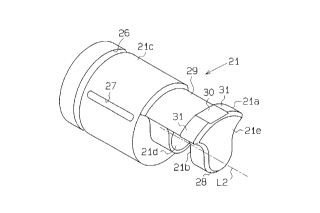
As shown in Figs. 1 through 4, each piston 21 has an
annular groove 26, which extends in the circumferential
direction along the cylindrical outer surface of the piston
21 near the top of the head 21c. As shown in Fig. 3, the
annular groove 26 is provided at a position where the groove
26 is not exposed to the inside of the crank chamber 15 when
-10-
CA 02210401 1997-07-14
the piston 21 is located at the bottom dead center position.
In Figs. 1 through 3, the swash plate 9 is shown at the
maximum inclination position.
Each piston 21 also has a linear groove 27, which
extends along the outer surface of the piston 21 parallel to
the axis L2 of the piston 21. One end of the linear groove
27 is located at the vicinity of the annular groove 26. The
linear groove 27 is located on the outer surface of the
piston 21 at a position described below. As shown in Fig.
4, when viewing the piston 21 so that the rotating direction
R of the rotary shaft 6 is clockwise (in this drawing, the
piston 21 is viewed from the skirt side), an imaginary
straight line L3 extends intersecting the axis L1 of the
drive shaft 16 and the axis L3 of the piston 21. Among the
two intersecting points P1, P2 at which the straight line L3
and the outer surface of the piston 21 intersect, the
position of the intersecting point P1, located at the
farther side of the outer surface with respect to the axis L
of the piston 21, is herein referred to as the twelve
o'clock position. In this case, the linear groove 27 is
located within a range E, which is defined between positions
corresponding to nine o'clock and eleven o'clock on the
outer surface of the piston 21.
As shown in Fig. 1, the position and length of the
linear groove 27 is determined so that it is not exposed
from the cylinder bore 12a to the inside of the crank
chamber 15 when the piston 21 moves to the top dead center
position. The linear groove 27 is not connected with the
annular groove 26.
The surface of the piston 21 is ground using a
-11-
CA 02210401 1997-07-14
centerless grinding method. In the centerless grinding
method, which is not shown, the workpiece, or piston 21, is
held on a rest and ground by rotating the piston 21 together
with a grinding wheel. The piston 21 is not held by a
chuck. Therefore, if a plurality of linear grooves 27 are
provided in the outer surface of the piston 21, the rotating
axis of the piston 21 placed on the rest becomes unstable.
This hinders precision grinding. Accordingly, it is
preferable that the number of linear grooves 27 be minimized
so as to enable accurate grinding when employing the
centerless grinding method. In this embodiment, the piston
21 is provided with only a single linear groove 27, the
width and depth of which are minimized but are sufficient to
supply lubricating oil to the crank chamber 15.
As shown in Figs. 1, 2, and 5, a substantially T-shaped
restrictor 21e is provided on each piston 21 at the distal
end of the skirt 21a. A sloped surface 28 extends along the
edge of the end face of the restrictor 21e. When the piston
21 moves from the top dead center position to the bottom
dead center position, the lubricating oil on the end face of
the skirt 21a and the inner surface of the front housing 11,
and the lubricating oil that collects at the bottom of the
crank chamber 15 is guided along the sloped surface 28
toward the portion connecting the piston 21 and the swash
plate 19, that is, toward the shoes 22.
A recess 29 facing toward the inner surface of the
front housing 11 extends along the skirt 21a adjacent to the
restrictor 21e. The restrictor 21e has a flat portion 30,
which is located at the middle of the surface facing the
inner surface of the front housing 11. The restrictor 21e
also has a pair of arched surfaces 31 serving to restrict
-12-
CA 02210401 1997-07-14
rotation of the piston 21. One arched surface 31 extends
from each side of the flat portion 30. The radius of
curvature of the arched surfaces 31 is substantially the
same as that of the inner surface of the front housing 11.
The arched surfaces 31 are in surface contact with the inner
surface of the front housing 11. A gap S1 is provided
between the flat portion 30 and the inner surface of the
front housing 11.
During reciprocation of each piston 21, the arched
surfaces 31 of the restrictor 21e slide against the inner
surface of the front housing 11. This prevents the piston
21 from rotating about its axis L2. Furthermore, during the
reciprocation of the piston 21, the lubricating oil in the
crank chamber 15 is guided toward the recess 29 through the
gap Sl between the flat portion 30 and the inner surface of
the front housing 11. The lubricating oil is then sent to
the connecting portion between the piston 21 and the swash
plate 19, or the shoes 22.
The operation of the compressor having the above
structure will now be described.
During the suction stroke, in which the piston 21 moves
from the top dead center position to the bottom dead center
position, the refrigerant gas in the suction chamber 13 is
drawn into the associated cylinder bore 12a. Furthermore,
some of the lubricating oil suspended in the refrigerant gas
is applied to the wall of the cylinder bore 12a. During the
discharge stroke, in which the piston 21 moves from the
bottom dead center position to the top dead center position,
the refrigerant gas in the cylinder bore 12a is compressed
and discharged into the discharge chamber 13b. Furthermore,
-13-
CA 02210401 1997-07-14
some of the refrigerant gas (blow-by gas) leaks into the
crank chamber 15 through a clearance C1 provided between the
outer surface of the piston 21 and the wall of the cylinder
bore 12a. As the blow-by gas passes through the clearance
C1, some of the lubricating oil suspended in the gas is
applied to the wall of the cylinder bore 12a.
The lubricating oil on the wall of the cylinder bore
12a is wiped off by the edge of the annular groove 26 in the
piston 21 and collects in the groove 26.
When the piston 21 undergoes the compression stroke,
the blow-by gas that leaks out of the cylinder bore 12a
increases the pressure in the annular groove 26. The linear
groove 27 is closed entirely by the wall of the cylinder
bore 12a only when the piston 21 is located in the vicinity
of the top dead center position. If the piston 21 moves
away from the top dead center position, at least a portion
of the linear groove 27 becomes exposed to the inside of the
crank chamber 15. This causes the pressure in the linear
groove 27 to become equal to or slightly higher than the
pressure of the crank chamber 15. The linear groove 27 is
communicated with the annular groove 26 through the narrow
clearance C1. Accordingly, when the piston 21 undergoes the
compression stroke, the difference between the pressure in
the annular groove 26 and the pressure in the linear groove
27 causes the lubricating oil in the annular groove 26 to
move through the clearance C1 and enter the linear groove
27. The lubricating oil that enters the linear groove 27
then enters the crank chamber 15 when the linear groove 27
becomes exposed to the inside of the crank chamber 15.
When the inclination of the swash plate 19 becomes
-14-
CA 02210401 1997-07-14
small, the linear groove 27 does not move out of the
cylinder bore 12a even if the piston 21 is at the bottom
dead center position. However, in this embodiment, the
distance between the linear groove 27 and the skirt side end
of the head 21c is short. This easily allows the
lubricating oil in the linear groove 27 to move into the
clearance C1 and enter the crank chamber 15.
The lubricating oil that enters the crank chamber 15 is
applied to the inner surface of the front housing 11 and
collects at the bottom of the crank chamber 15. As each
piston 21 moves from the top dead center position to the
bottom dead center position during the suction stroke, the
lubricating oil moves along the sloped surface 28, which is
provided along the edge of the end face of the skirt 21a, to
the connecting portion between the piston 21 and the swash
plate 19, or the shoes 22. In addition, the lubricating
oil, especially the oil on the inner surface of the front
housing, is guided through the gap Sl between the flat
portion 30 and the inner surface of the front housing 30 and
enters the recess 29. The lubricating oil subsequently
lubricates the connecting portion between the piston 21 and
the swash plate 19.
Accordingly, when each piston 21 undergoes the suction
stroke, the lubricating oil on the end face of the skirt 21a
and the inner surface of the front housing 11, and the
lubricating oil that collects at the bottom of the crank
chamber 15 is not dispersed by the movement of the end face
of the skirt 21a. This causes more effective lubrication of
the connecting portion between the piston 21 and the swash
plate 19, which is one of the portions that definitely
requires lubrication.
-15-
CA 02210401 1997-07-14
As described above, the flat portion 30 is provided on
a portion of the surface of the restrictor 21e that faces
the inner surface of the front housing 11. The pair of
arched surfaces 31, which come into surface contact with the
inner surface of the front housing 11, extend from each side
of the flat portion 30 with a predetermined interval
therebetween. Therefore, the entire surface facing the
front housing 11 need not be accurately machined to an arch
having the same radius of curvature as the inner surface of
the front housing 102. This facilitates the machining of
the restrictor 21e.
The flat portion 30, or recessed portion, provided
between the pair of arched surfaces 31 forms a gap S1
between the inner surface of the front housing 11. Thus,
when the piston 21 reciprocates, lubricating oil is
efficiently applied to the joint between the piston 21 and
the swash plate 19 through the gap Sl.
The radius of curvature of the arched surfaces 31 is
substantially the same as that of the front housing 11.
This maximizes the contact area between the restrictor 21e
and the inner surface of the front housing 11 regardless of
the flat portion 30, which extends along the surface facing
toward the inner surface of the front housing 11 but does
not contact the inner surface. This further effectively
prevents the piston 21 from rotating about its axis L2 and
stabilizes the movement of the piston 21.
The sloped surface 28 extends along the edge of the end
face of the restrictor 21e. Thus, the lubricating oil on
the inner surface of the front housing 11 is efficiently
directed by the sloped surface 28 to the joint between the
-16-
CA 02210401 1997-07-14
piston 21 and the swash plate 19.
A second embodiment according to the present invention
will now be described with reference to Fig. 6. In the
second embodiment, there are three flat portions 30. One at
the middle of the surface facing the inner surface of the
front housing 11 and the other two on each side of the first
one. A gap S1 is defined between each flat portion 30 and
the inner surface of the front housing 11. These gaps S1
allow passage of the lubricating oil.
The intersections between the middle flat portion 30
and the flat portions 30 on each side of the middle flat
portion 30 form corners. Each corner, or contact portion
32, extends parallel to the axis L2 of the piston 21 and
comes into linear contact with the front housing 11. In
this embodiment, the contact portions 32 serve to restrict
the rotation of the piston 21. When the piston 21
reciprocates, the contact portions 32 slide against the
inner surface of the front housing 11 and prevent the piston
21 from rotating about its axis L2.
Accordingly, the advantageous effects of the first
embodiment may be obtained in the second embodiment. In the
second embodiment, the restrictor 21e has a plurality of
flat surfaces 30, which define a plurality of contact
portions 32. The contact portions 32 come into linear
contact with the inner surface of the front housing 11.
Accordingly, the surface facing the inner surface of the
front housing 11 need only be machined flat. It is not
necessary to machine the surface in an arched manner. This
further facilitates the machining of the restrictor 21e. In
addition, the lubricating oil from the crank chamber 15
-17-
CA 02210401 1997-07-14
passes through the plurality of gaps Sl and lubricates the
connecting portion between the piston 21 and the swash plate
19 further efficiently.
A third embodiment according to the present invention
will now be described with reference to Fig. 7. Like the
first embodiment, in the third embodiment, the flat portion
30 is provided at the middle of the surface of the
restrictor 21e facing the inner surface of the front housing
11. A pair of lips 33, which serve to restrict the rotation
of the piston 21, is provided on the sides of the flat
portion 30. The lips 33 extend parallel to the axis of the
piston 21 and contact the inner surface of the front housing
11. When the piston 21 reciprocates, the lips 33 slide
against the inner surface of the front housing 11 and
prevents the piston 21 from rotating about its axis L2.
The advantageous effects of the first and second
embodiment is also obtained in the third embodiment.
Furthermore, in this embodiment, the lips 33 form a large
gap S1 between the flat portion 30 and the inner surface of
the front housing 11 to allow passage of the lubricating
oil. Thus, when the piston 21 reciprocates, the lubricating
oil from the crank chamber 15 passes through the large gap
S1 and lubricates the joint between the piston 21 and the
swash plate 19 further efficiently.
Although several embodiments of the present invention
have been described so far, it should be apparent to those
skilled in the art that the present invention may be
embodied in many other specific forms without departing from
the spirit or scope of the invention. More particularly,
the present invention may be modified as described below.
-18-
CA 02210401 1997-07-14
In the restrictor 21e, the structure of the portion
that serves to restrict rotation of the piston 21 is not
limited as long as there are two or more of such portions
with a predetermined interval therebetween.
S
In the first, second, and third embodiments, the flat
portion 30 defines the gap S1 between the restrictor 21e and
the inner surface of the front housing 11. However, instead
of using the flat portion 30, a groove or recess provided in
the restrictor 21e may be used to define the gap Sl.
Therefore, the present examples and embodiments are to
be considered as illustrative and not restrictive and the
invention is not to be limited to the details given herein,
but may be modified within the scope of the appended claims.
-19-